1
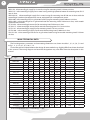
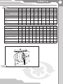
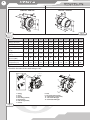
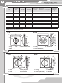
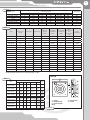
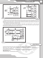
USER ПО MANUAL РУКОВОДСТВО ЭКСПЛУАТАЦИИ CENTRIFUGAL INLINE FANS VKM / VKMZ / VC SERIES 2 VKM / VKMz / VC CONTENT Use Delivery set Structural designation key Main technical data Safety requirements Fan design Connection to power mains Maintenance Storage requirements Manufacturer’s warranty Acceptance certificate 3 3 3 4 10 10 12 13 14 14 15 3 USE The present user manual contains the product description, technical data, operation, installation and mounting guidelines for the centrifugal inline fans of VENTS VKM, VKMz, VC series, hereinafter referred to as the fan. The fans are designed for ventilation of domestic, public and manufacturing premises heated during winter. Transported air must not contain dust, solid and sticky particles and fibrous materials. The transported air temperature must be within the limits stated in fig. 1, 3, 5. The fan is designed for horizontal or vertical mounting in a round air duct and are used both for extract and supply ventilation. The fan is rated for continuous operation always connected to power mains. The fan must be grounded. Ingress Protection Rating IPX4. DELIVERY SET The delivery set includes: f an - 1 item; fixing bracket - 2 items (for series VKM, VKMC, VKM Q, VKMz), for VKM E series - 1 item; user manual; packing box. STRUCTURAL DESIGNATION KEY Х X X X Х P - smooth speed controller Un - speed controller with temperature sensor E - equipped with energy-saving motor Q - low-watt motor Exhaust spigot diameter 100; 125; 150; 200; 250; 315; 355; 400; 450 mm S - high-powered motor Fan name: VKM - inline centrifugal fan in metal casing VKMz - inline centrifugal fan in galvanized steel casing VC-VK - inline centrifugal extract fan for outside installation VC-PK - inline centrifugal supply fan for installation into air duct VC-PN - inline centrifugal supply fan for outside installation VCz-VN - inline centrifugal extract fan for outside installation in galvanized steel casing 4 VKM / VKMz / VC VKM 150 - inline centrifugal supply fan in metal casing for mounting into Ø 150 mm air duct. VKMS 315 - inline centrifugal supply fan in metal casing with high-powered motor for mounting into Ø 315 mm air duct. VKM 250 Un - inline centrifugal supply fan in metal casing for mounting into Ø 250 mm air duct with the control logic based on the temperature sensor, equipped with a temperature sensor. VKMz 200 - inline centrifugal fan in galvanized steel casing for mounting into Ø 200 mm air duct. VKMz 160P - inline centrifugal fan in galvanized steel for mounting into Ø 160 mm air duct, with smooth speed control function. VC-VK 250 - inline centrifugal extract fan for mounting into Ø 250 mm air duct. VC-VN 315 - inline centrifugal extract fan for outside mounting into Ø 315 mm air duct. VC-PK 125 - inline centrifugal supply fan for mounting into Ø 125 mm air duct. VC-PN 100 - inline centrifugal supply fan for outside mounting into Ø 100 mm air duct. VCz-VN 150 - inline centrifugal extract fan in galvanized steel casing for outside mounting into Ø 150 mm air duct. MAIN TECHNICAL DATA The fan designation, parameters and connecting dimensions are shown in tables 1, 2, 3, 4, 5, 6, 7, 8 and in fig. 1, 2 , 3, 4. 5, 6, 7, 8, 9, 10, 11, 12. Due to the constant improvements the design of some models may slightly differ from those described in this manual. The wiring diagram and terminal designation may also differ from the description in this manual. Table 1 Type Dimensions [mm] D D1 В В1 L L1 L2 L3 Weight [kg] Fig. no. VKM 100 Е 100 204 - - 195 20 20 258 3,9 1 VKM 100 Q 98 254 298 258 205 20 25 30 4,2 2 VKM 100 98 254 298 258 205 20 25 30 4,4 2 VKM 125 Е 125 204 - - 195 20 20 258 3,9 1 VKM 125 Q 123 254 298 258 205 20 25 30 4,1 2 VKM 125 123 254 298 258 205 20 25 30 4,3 2 VKM 150 Q 149 304 349 309 200 20 25 30 5,4 2 VKM 150 149 340 349 309 220 25 25 30 5,4 2 VKMS 150 149 340 386 346 226 20 20 40 5,7 2 VKM 160 Q 159 304 349 309 200 20 25 30 5,4 2 VKM 160 159 304 357 317 220 25 25 30 5,6 2 VKMS 160 159 340 357 346 226 20 20 40 5,7 2 VKM 200 198 344 390 350 240 25 29 40 6,6 2 VKMS 200 198 344 390 350 250 25 29 40 6,7 2 VKM 250 Q 248 344 390 350 249 25 31 40 7,1 2 VKM 250 248 344 390 350 249 25 31 40 7,3 2 VKM 315 314 404 454 414 260 25 40 40 8,1 2 VKMS 315 314 404 454 414 288 25 40 40 8,2 2 VKM 355 Q 353 460 522 522 506 60 60 70 12,8 3 VKM 400 398 570 634 570 506 60 60 70 20,0 3 VKM 450 448 608 663 634 570 60 60 80 30,0 3 Allowable deviation of the rated voltage: ±10% 5 Табл.2 VKM 100 Е VKM 100 Б VKM 100 VKM 125 Е VKM 125 Б VKM 125 VKM 150 Б VKM 150 VKMS 150 VKM 160 Б Voltage, 50 Hz [V] 230 230 230 230 230 230 230 230 230 230 Power [W] 27 60 73 27 60 75 75 98 116 73 Current [A] 0,13 0,37 0,32 0,13 0,37 0,33 0,33 0,43 0,52 0,33 Max. air capacity [m3/h] 180 210 270 240 255 355 470 55 645 470 Rotation per minute [min-1] 2745 2620 2830 2780 2535 2800 2515 2705 2625 2500 Noise level at 3 m distance [dBA] 32 36 47 32 36 47 46 47 50 46 Max. transported air temperature [°C] -25 +55 -25 +55 -25 +55 -25 +55 -25 +55 -25 +55 -25 +55 -25 +55 -25 +55 -25 +55 Ingress Protection IP X4 IP X4 IP X4 IP X4 IP X4 IP X4 IP X4 IP X4 IP X4 IP X4 VKM 160 VKMS 160 VKM 200 VKMS 200 VKM 250 Б VKM 250 VKM 315 VKMS 315 VKM 355 Б VKM 400 VKM 450 Voltage, 50 Hz [V] 230 230 230 230 230 230 230 230 230 230 230 Power [W] 98 115 154 193 158 194 171 296 233 460 665 Current [A] 0,43 052 0,67 0,84 0,69 0,85 0,77 1,34 1,06 2,23 2,89 Max. air capacity [m3/h] 555 645 950 1100 1190 1310 1400 1880 2210 3050 5260 Rotation per minute [min-1] 2660 2650 2375 2780 2315 2790 2600 2720 1375 1370 1265 Noise level at 3 m distance [dBA] 47 50 48 51 52 52 52 54 58 61 65 Max. transported air temperature [°C] -25 +55 -25 +55 -25 +50 -25 +45 -25 +50 -25 +50 -25 +50 -25 +45 -25 +45 -25 +80 -25 +70 Ingress Protection IP X4 IP X4 IP X4 IP X4 IP X4 IP X4 IP X4 IP X4 IP X4 IP X4 IP X4 VKM 100 Е - VKM 125 Е Fig. 1 6 VKM / VKMz / VC VKM 355- VKM 450 VKM 100 - VKM 315 Fig. 3 Fig. 2 Table. 3 VKMz 100 Б VKMz 100 VKMz 125 Б VKMz 125 VKMz 150 VKMz 160 VKMz 200 Б VKMz 200 VKMz 250 Б VKMz 250 VKMz 315 Б VKMz 315 Voltage, 50 Hz [V] 230 230 230 230 230 230 230 230 230 Power [W] 60 72 60 78 75 78 139 157 134 230 230 230 152 1513 Current [A] 0,37 0,32 0,37 0,34 0,33 0,34 0,61 0,69 185 0,59 0,66 0,66 0,81 Max. air capacity [m3/h] 195 250 230 330 455 455 840 1000 980 1070 1330 1540 Rotation per minute [min-1] 2670 2820 2605 2820 2770 2760 2790 2740 2785 2785 2680 2730 Noise level at 3 m distance [dBA] 35 46 35 46 46 46 48 50 51 52 52 53 Max. transported air temperature [°C] -25 +55 -25 +55 -25 +55 -25 +55 -25 +55 -25 +55 -25 +55 -25 +55 -25 +55 -25 +55 -25 +55 -25 +55 Ingress Protection IP X4 IP X4 IP X4 IP X4 IP X4 IP X4 IP X4 IP X4 IP X4 IP X4 IP X4 IP X4 Allowable deviation of the rated voltage: ±10% VKM 100Е, VKM 125 Е VKM 100...315 VKM...Un 11 12 9 5 1 3 2 6 10 4 7 VKM...P 9 4 8 7 3 2 6 5 1 - casing; 2 - cover; 3 - screws; 4 - inner fixing bracket; 5 - terminal box; 6 - outer fixing bracket; 7 - screws; Fig. 4 8 - bolt; 9 - fan speed control knob; 10 - temperature control knob; 11 - fan on/off LED light; 12 - thermostat LED light. 1 7 VKMz 100 - VKMz 315 Fig. 5 Table 4 Dimensions [mm] В В1 L L1 L2 L3 Weight [kg] 237 253 293 202 23 22 30 3,1 237 253 293 202 23 22 30 3,2 123 237 253 293 202 23 22 30 3,1 VKMz 125 123 237 253 293 202 23 22 30 3,15 VKMz 150 148 278 294 334 200 25 23 30 3,8 VKMz 160 158 278 294 334 200 25 23 30 3,8 VKMz 200 Q 198 332 340 380 245 25 29 40 4,2 VKMz 200 198 332 340 380 245 25 29 40 4,4 VKMz 250 Q 249 332 340 380 213 25 29 40 4,1 VKMz 250 249 332 340 380 213 25 29 40 4,3 VKMz 315 Q 315 402 410 450 308 33 55 40 5,5 VKMz 315 315 402 410 450 308 33 55 40 5,7 Type D D1 VKMz 100 Q 98 VKMz 100 98 VKMz 125 Q VKMz...Un 1 - casing; 2 - cover; 3 - screws; 4 - inner fixing bracket; 5 - terminal box; 6 - outer fixing bracket; 7 - screws; 8 - bolt; 9 - fan speed control knob; 10 - temperature control knob; 11 - fan on/off LED light; 12 - thermostat LED light. Fig. 6 11 12 9 5 1 3 2 10 VKMz...P 9 4 8 7 6 8 VKM / VKMz / VC Table 5 Type Voltage, 50 Hz [V] Power [W] Current [A] Max. air capacity [m3/h] Rotation per minute [min-1] Noise level at 3 m distance [dBA] Max. transported air temperature [°C] VC 100 Q 230 60 0,37 210 2620 36 -25 +55 VC 100 230 73 0,32 270 2830 47 -25 +55 VC 125 230 60 0,37 255 2535 36 -25 +55 VC 125 Q 230 75 0,33 355 2800 47 -25 +55 VC 150 230 98 0,43 555 2705 47 -25 +55 VC 160 230 98 0,43 555 2660 47 -25 +55 VC 200 230 154 0,67 950 2375 48 -25 +50 VCS 200 230 193 0,84 1100 2780 51 -25 +45 VC 250 Q 230 158 0,69 1190 2315 52 -25 +50 VC 250 230 194 0,85 1310 2790 52 -25 +50 VC 315 230 171 0,77 1400 2600 52 -25 +55 VCS 315 230 296 1,34 1880 2720 54 -25 +45 Allowable deviation of the rated voltage: ±10% VC-VN VC-VK 1 - casing; 2 - fixing bracket; 3 - screws; 4 - motor-impeller block; 5 - terminal box; 1 - casing; 2 - fixing bracket; 3 - motor-impeller block; 4 - terminal box. 5 - screws. Fig.8 Fig. 7 VC-PK VC-PN 1 - casing; 2 - fixing bracket; 3 - screws; Fig. 9 4 - base plate; 5 - motor-impeller block; 6 - terminal box. 1 - casing; 2 - fixing bracket; 3 - motor-impeller block; 4 - terminal box; 5 - screws; 6 - base plate. Fig.10 9 Table 6 Dimensions [mm] Type C 10 10 10 10 12 12 12 VC 100 Q \ VC 100 VC 125 Q \ VC 125 VC 150 VC 160 VC 200 \ VCS 200 VC 250 Q \ VC 250 VC 315 \ VCS 315 D 249 249 249 249 339 339 339 d 98 123 149 159 164 164 315 A 435 435 435 435 595 595 595 H/H1 150 / 120 150 / 120 153 / 123 153 / 123 171 / 141 172 / 142 209 / 179 Table 7 E 330 330 330 330 450 450 450 Max. Noise level at transported 3 m distance air [dBA] temperature [°C] Weight [kg] 3,24 3,24 4,26 4,3 6,1 5,9 7,2 Max. air capacity [m3/h] Rotation per minute [min-1] 0,37 195 2670 35 -25 +55 IP X4 0,32 250 2820 46 -25 +55 IP X4 60 0,37 230 2605 35 -25 +55 IP X4 230 78 0,34 330 2820 46 -25 +55 IP X4 IP X4 Type Voltage, 50 Hz [V] Power [W] Current [A] VCz 100Q-VN 230 60 VCz 100-VN 230 72 VCz 125Q-VN 230 VCz 125-VN Ingress Protection VCz 150-VN 230 75 0,33 455 2770 46 -25 +55 VCSz 150-VN 230 97 0,43 720 2760 46 -25 +55 IP X4 VCz 160-VN 230 78 0,34 455 2760 46 -25 +55 IP X4 IP X4 VCSz 160-VN 230 97 0,43 720 2765 46 -25 +55 VCz 200Q-VN 230 139 0,61 840 2790 48 -25 +50 IP X4 VCz 200-VN 230 157 0,69 1000 2740 50 -25 +50 IP X4 IP X4 VCSz 200-VN 230 193 0,84 1150 2780 51 -25 +50 VCz 250Q-VN 230 134 0,59 980 2785 51 -25 +50 IP X4 VCz 250-VN 230 152 0,66 1070 2765 52 -25 +50 IP X4 VCSz 250-VN 230 175 0,77 1185 2745 52 -25 +50 IP X4 VCz 315Q-VN 230 151 0,66 1330 2680 53 -25 +50 IP X4 VCz 315-VN 230 185 0,81 1540 2730 53 -25 +50 IP X4 VCSz 315-VN 230 270 1,18 1755 2730 53 -25 +50 IP X4 Allowable deviation of the rated voltage: ±10% VCz-VN Table 8 Type VCz 100Q-VN VCz 100-VN VCz 125Q-VN VCz 125-VN VCz 150-VN VCSz 150-VN VCz 160-VN VCSz 160-VN VCz 200Q-VN VCz 200-VN VCSz 200-VN VCz 250Q-VN VCz 250-VN VCSz 250-VN VCz 315Q-VN VCz 315-VN VCSz 315-VN Dimensions [mm] C D d A H/H1 E Weight [kg] 6 235 98 310 115/90 295 3,2 6 235 123 310 115/90 295 3,2 6 275 148 400 128/92 385 4,26 6 275 159 400 128/92 385 4,3 6 333 198 400 130/115 385 5,3 6 333 198 400 130/115 385 5,5 6 333 248 400 134/114 385 7,1 6 333 248 400 134/114 385 7,8 6 400 313 460 172/142 445 8 6 400 313 460 194/142 445 8,5 1 - casing; 2 - fixing bracket; 3 - motor-impeller block; Fig. 11 4 - terminal box; 5 - screws. 10 VKM / VKMz / VC SAFETY REQUIREMENTS Take steps to prevent ingress of smoke, carbon monoxide and other combustion products into the room through open chimney flues or other fire-protection devices. Mounting and maintenance of the fan are allowed only by duly qualified electricians in compliance with valid rated norms. Disconnect the fan from power mains prior to any servicing and repair works. Before connecting the fan to power mains check the fan for any visible damages of impeller and casing. The fan casing must not contain any foreign objects which can damage the impeller blades. WARNING: Do not use the fan in explosive or fire-hazardous environment. Misuse of the fan or any unauthorized modification is not allowed. If the fan is subjected to water sprays from all directions (IPX4), it must be extra protected against water ingress. Possible options: 1. Connect a straight air duct section at least 1 m long to the intake spigot in case of horizontal fan installation. 2. In case of any installation option install an outer hood on the intake spigot. FAN DESIGN VKM and VKMz fan (fig. 4, 6) consists of the casing 1, the motor-impeller block that is attached to the fixing bracket 4, the cover 2 that is fixed to the casing with screws 3 (the casing spigot diameter und the cover diameter are equal to the connected air duct diameter), the terminal block 5 that incorporates a terminal block and a capacitor (fig. 1, 5) and enables connection of the fan to power mains. The fan models with the speed controller and thermostat are equipped with a speed control knob 9, a thermostat control knob 10, a fan on/off LED light indicator 11 and a thermostat LED light indicator 12 that are located on the terminal box cover. The fan models with the speed controller are equipped with a speed control knob 9 which is located on the terminal box 5 cover. The fan models with a speed controller and a speed controller with a thermostat are connected to power mains through a power cable with a plug. The fan is designed for vertical mounting. The air direction in the system must match the pointer direction on the fan casing. Mounting sequence for fixing the fan on the wall or to the ceiling: - remove the bolt from the casing 1 and install the fixing brackets in such a way so that the holes on the fixing brackets are aligned with the heads of the screws 3; - fix the fixing brackets on the casing with bolts; - drill the holes in the mounting surface to match the fitment holes of the fixing brackets; - fix the fan with the screws; - connect the air ducts of the respective size to the fan and fix them with clamps. 11 Temperature and speed controller: This option is available for the models VKM Un, VKMz Un. The temperature and speed controller is designed for air temperature control and fan speed control depending on ambient air temperature. The fan models VKM Un, VKMz Un are equipped with an external temperature sensor fixed on 4 m cable. The cover of the terminal block (fig. 4, 6) incorporates the following controls: - fan speed control knob 9; - thermostat control knob 10 to set the thermostat temperature threshold; - on/off LED light indicator 11; - thermostat LED light indicator 12. Control logic of VKM Un, VKMz Un fans. Set the thermostat temperature threshold with the thermostat control knob 10. Turn the fan on and then set the fan speed with a speed control knob 9. The fan on/off light indicator 11 glows. The controller switches the fan to the maximum speed (maximum air flow) as the temperature rises and crosses the thermostat setpoint. The thermostat light indicator 12 glows if the temperature is above the thermostat setpoint. After the temperature falls 2°C below the thermostat set point, the fan reverts to the pre-set lower speed. This way the motor frequent speed switches during its operation in the environment with the temperature close to the threshold value are prevented. This control logic enables tracking temperature fluctuations and respond to the temperature change with accuracy up to 2°C. The rate of the speed switching depends exclusively on the air temperature fluctuations. Speed controller: This option is available for the models VKM P, VKMz P (fig. 4, 6). It is used for the fan smooth speed control which is set by the speed control knob 9. VC-VK fan (fig. 7) consists of the casing 1 with the motor and impeller block 4 fixed on the fixing bracket 4 inside. The fixing bracket is attached to the casing with four screws 3. The terminal box 5 is attached to the casing bottom on the intake spigot side to enable connection to power mains and placement of the capacitor. Mounting sequence for fixing the fan on the wall or to the ceiling: - drill the holes in the mounting surface to match the fitment holes in the fan basement and fix the fan with screws. The fan VC-VN, VCz-VN (fig. 8, 11) consists of the casing 1 with the motor-impeller block 3 attached to the fixing bracket 2 inside. The casing is attached to the base plate with screws 5. The terminal box 4 is located on top of the casing on intake spigot side to facilitate connection of the fan to power mains and placement of the capacitor. Mounting sequence for fixing the fan on the wall or to the ceiling: - drill the holes in the mounting surface to match the fitment holes in the fan basement; - fix the fan with screws. The fan VC-PN (fig. 9) consists of the casing 1 with the motor-impeller block 5 attached to the fixing bracket 2 inside. The fixing bracket is attached to the casing with four screws 3. The terminal box 6 is located on top of the casing on intake spigot side to facilitate connection of the fan to power mains and placement of the capacitor. Mounting sequence for fixing the fan on the wall or to the ceiling: - drill the holes in the mounting surface to match the fitment holes in the fan basement; - fix the fan with screws. 12 VKM / VKMz / VC The fan VC-PK (fig. 10) consists of the casing 1 with the motor-impeller block 3 attached to the fixing bracket 2 inside. The fixing bracket 2 is attached to the casing with four screws 5. The exhaust hole of the fan is covered with a grille. The terminal box 4 is located on top of the casing on intake spigot side to facilitate connection of the fan to power mains. Mounting sequence for fixing the fan on the wall or to the ceiling: - drill the holes in the mounting surface to match the fitment holes in the fan basement; - fix the fan with screws. CONNECTION TO POWER MAINS Cut power supply off before any operations with the fan. The fan must be connected to power mains by a duly qualified electrician. The rated electrical parameters of the fan are shown on the sticker. Any modifications of the internal connections are not allowed and will void the warranty. The fan is rated for connection to single-phase ac 230 V / 50 Hz power mains. Connect the fan to power mains by means of insulated, durable and thermal-resistant cords (cables, wires). Install the automatic circuit breaker at the external electric input 230 V / 50 Hz and integrate it into the fixed wireworks. Install the automatic circuit breaker QF in such a way to provide quick unhampered access to it in case of emergency. The trip current must be in compliance with the fan current consumption. The recommended rated current: - 2 A for the fans VKMS 315, VKM 355Q, VCS 315; - 3.15 A for the fans VKM 400, VKM 450; - 1 A for all other fans. The recommended wire cross section is 0.75 mm2. The above cross section is for reference only. The applicable cable must be selected in consideration of the maximum wire temperature depending on the wire and insulation type, the maximum current, the lead wire length and its layout type. Connect the cables to the terminal block incorporated inside the terminal box located on the fan casing in compliance with the fan wiring diagram and the terminal designation. The terminal designations are shown on the sticker inside the fan casing. The wiring diagram for the fans VKM 400, VKM 450 is shown in fig. 13. The wiring diagram for the other fans is shown in fig. 12. The fans with a speed controller and temperature and speed controller (VKM Un, VKMz Un, VKM P, VKMz P) are designed for connection to single-phase ac power mains 230 V / 50 Hz and are equipped with a power cord and a plug (supplied connected to the terminal block). 13 Fig. 12 Fig. 13 The terminals TW1, TW2 are the electrical leads of the normally closed contact of the motor overheating protection. Connect the contact in series to power circuit of the magnetic starter coil KM1 that starts the motor after pressing the button S1. After the motor overheating the contact gets broken and switches the starter coil off to cut power off and stop the motor. The automatic circuit breaker QF, the magnetic starter KM1, the control knobs S1 and S2 are not included into the delivery set and are installed by the users. The motor connection example with leaded outside thermal protecting contacts are shown in fig. 14. Fig. 14 MAINTENANCE Disconnect the fan from power mains prior to maintenance and servicing operations. Maintenance means regular cleaning of the fan surfaces from dust and dirt. Use a soft dry brush or a vacuum cleaner to remove dust. The impeller blades require thorough cleaning once in 6 months. Cleaning procedure: VKM, VKMz (fig. 4, 6) remove the screws 3 and take off the cover 2. 14 VKM / VKMz / VC VC-VK (fig. 7) - remove the screws 3 and pull out the motor-impeller block with the fixing bracket 2. VC-VN, VCz-VN (fig. 8, 11) - remove the screws 5 and pull out the motor-impeller block with the fixing bracket 2. VC-PN (fig. 9) - remove the screws 3 and pull the fixing bracket 2 with the impeller 5 out of the casing. VC-PK (fig. 10) - remove the screws 5 and pull the fixing bracket 2 with the impeller 3 out of the casing 1. Clean the impeller blades with a soft cloth wetted in mild water detergent solution. Avoid liquid dripping on the motor. STORAGE REQUIREMENTS Store the fan in the manufacturer’s original packing box in a dry ventilated premise at the temperatures from +5°C up to + 40°C and relative humidity less than 80% (at the temperature +20°C). Acid, alkali vapours and other aggressive substances are not allowed in the storage environment. MANUFACTURER’S WARRANTY The fan is manufactured at the factory of “Ventilation systems” Pr JSC (hereinafter referred to as the Manufacturer). By purchasing this product the customer confirms to have read and agreed to the warranty terms. The manufacturing company sets forth the warranty period (service life) of the product as 24 months following the sale date via retail network subject to the customer’s ensuring compliance with the rules of transportation, storage, mounting and operation of the product. In case of no confirmation of the sales date the warranty period is calculated from the manufacturing date. All the units and components belonging to the faulty unit and replaced within the warranty period shall be covered by the previous warranty period and general warranty conditions. Thus the warranty period is neither extended nor renewed for the replaced components or the unit. In case of failure due to faulty equipment during the warranty period the consumer has the right to get it exchanged at the manufacturing facility. For the product replacement please contact your Seller. The accessories operated together with the unit, both included and not included into the delivery list as well as other equipment operating jointly with the unit are not covered by the warranty. The company is not responsible for compatibility of their goods with other producers’ goods. The warranty covers the manufacturing defects only. All the defects and faults resulting from gross mechanical effect during operation process or natural wear-and-tear are not covered by the warranty conditions. The faults caused by violence of operation, servicing and maintenance guidelines either by Customer or third parties or caused by unauthorized design modifications shall not be covered by warranty. WARRANTY LIMITATION The manufacturer is not responsible for any mechanical or physical damages resulting from the manual requirements violence, the unit misuse or gross mechanical effect. Indirect damages such as re-installation or re-connection of the unit, direct or indirect losses related to the unit replacement shall not be indemnified. Mounting/dismantling, connection/disconnection and adjustment of the unit shall not be covered by the warranty. The contractor in charge for mounting, electric mounting and adjustment works shall be responsible for quality and warranty of these works. In any case the indemnity amount shall not exceed the actually paid value for the defective unit price. 15 ACCEPTANCE CERTIFICATE VENTS fan_ _______________________________________has been duly certified as serviceable. (fill the field) We hereby declare that the following product complies with the essential protection requirements of Electromagnetic Council Directive 2004/108/EC, 89/336/EEC and Low Voltage Directive 2006/95/EC, 73/23/EEC and CE-marking Directive 93/68/EEC on the approximation of the laws of the Member States relating to electromagnetic compatibility. Stamp of the acceptance inspector Date of production __________________________ Sold by name of the vendor, stamp of the retailer _________________________________________________ ___________________________________________________________________________________ Sale date _____________________________ WARRANTY CARD 2012 V05ENG-06