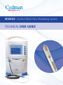
1
Hemedex Cerebral Blood Flow Monitoring System
®
technical user guide
Table of Contents
INTRODUCTION .............................................................................................................3
Bowman Perfusion Monitor®..............................................................................4
Section 1: Bowman Perfusion Monitor General Overview.............................4
Section 2: Monitor Set Up.........................................................................................7
Section 3: Measurement Cycle................................................................................8
Section 4: User Interface Menu................................................................................9
PROBE PLACEMENT IN THE O.R....................................................................................14
Section 1: Intra-Operative Indications & Suggested Site for Probe Insertion ....14
Section 2: Insertion Through a Burr Hole Adjacent to the Craniotomy................14
Section 3: Insertion Through the Craniotomy.........................................................15
Section 4: Confirm K Value.......................................................................................16
Section 5: Potential Sources of Interference...........................................................17
PROBE PLACEMENT IN THE ICU ...................................................................................18
Section 1: Probe Insertion and Fixation Protocol with Tunneling........................18
Section 2: Probe Insertion and Fixation Protocol with Bolt.................................19
Section 3: Confirm K Value......................................................................................20
Section 4: Potential Sources of Interference.........................................................21
FREQUENTLY ASKED QUESTIONS (FAQs).....................................................................22
TROUBLESHOOTING GUIDE............................................................................................25
REFERENCES....................................................................................................................26
2
INTRODUCTION
Purpose
The purpose of this guide is to aid Bowman Perfusion Monitor® users with technical
knowledge of Bowman Perfusion Monitor, the placement and fixation of the QFlow 500™
Perfusion Probe, and to help in understanding the data recorded by the Bowman Perfusion
Monitor. This Technical Manual provides a general technical overview and is not intended to
replace the User Manual or IFUs for individual products. For detailed information, please refer
to the User Manual of the Bowman Perfusion Monitor and IFU for the QFlow 500 Perfusion
Probes. The successful use of the Bowman Perfusion Monitor requires that:
• The probe is inserted at the proper site and at the proper depth for the given indication
• The probe is kept fixed at this location
• The data is properly interpreted and utilized by physicians to aid them in patient management
The following sections should aid in this process.
Audience
This guide is intended for Bowman Perfusion Monitor and QFlow 500 Perfusion Probe users.
Basic knowledge of neuroanatomy and procedures is assumed.
Background
The QFlow 500 is intended for extravascular monitoring of microcirculation blood flow in buried
tissues.
Hemedex® CBF Monitoring System consists of the Bowman Perfusion Monitor, the QFlow
500 Perfusion Probe, connecting umbilical cable and power cable. It is FDA cleared for measuring
cerebral blood flow in brain white matter.
Hemedex CBF Monitoring System is developed based on thermal diffusion technology, and is
currently the only minimal invasive technology available that measures cerebral blood flow in
absolute unites continuously. The monitor has an intuitive graphical user interface, a color display
screen, and a thermal printer. The probe’s diameter is 1.1mm.
As of early 2007, Codman and Shurtleff, Inc. acquired exclusive rights to distribute the Hemedex
CBF Monitoring System and accessory products in United States for measurement of cerebral
blood flow.
3
Bowman Perfusion Monitor
(Please refer to the User Manual for complete and detailed instructions)
Section 1: Bowman Perfusion Monitor General Overview
The Bowman Perfusion Monitor is designed as a stand-alone unit for patient bedside use.
It has capabilities for linking to other systems. The monitor connects directly at to any standard
RS-232 serial port. The analog output (BNC) connector of the monitor may be attached to a userselected auxiliary analog voltage data collection device. The QFlow 500 probes must be inserted
properly into the target tissue and attached to the monitor. The electronic hardware specifications
are as follows:
The physical specifications for the Bowman Perfusion Monitor are as follows:
Dimensions
16.6 X 11.9 X 10.1 inches (42.2 X 30.2 X 25.7 cm)
Weight
10 lbs. (4.5 kg)
Operating Temperature Range
32° to 122°F (0° to 50°C)
Storage Temperature Range
-4° to 140°F (-25° to 60°C)
Storage Humidity Range
20% to 90% RH
Analog output specifications are as follows:
4
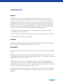
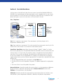
Front Panel
The front panel of the Bowman Perfusion Monitor (Model 500) holds the power switch,
printer, display screen, menu buttons, and umbilical cord connector (for the QFlow 500 probe).
To take measurement, a QFlow 500 probe must be properly placed in the target tissue, and
connected to the umbilical cord, and the umbilical cord must be connected to the monitor. The
monitor checks for a probe to start the measurement, and continues checking to ensure the
probe is not disconnected during the measurement. The message line at the top of the display
screen will indicate the progress in measurement cycle as well as warning messages if
there is any problem with the probe, the monitor, or performing perfusion measurements.
MESSAGE
LINE
PERFUSION
NUMERIC
DISPLAY
PERFUSION
vs. TIME
GRAPH
UMBILICAL
CORD
CONNECTOR
MENU
LABELS
MENU
BUTTONS
ON / OFF
SWITCH
PRINTER
Paper Slot
Umbilical
cord
QFLOW 500
probe
Printer and Load Paper
The printer records the real-time perfusion measurements on paper for review and record
keeping. When “Print” option is requested, the data shown on the display screen will be printed
with the probe label and the unique probe ID number with options to Print Perfusion; Print
Perfusion & Temperature; Print K Values; or Print Settings.
Load paper in the Bowman Perfusion Monitor before operating. The printer uses standard
50mm thermographic print rolls. To load paper in the printer:
1. Open printer access panel by flipping door down.
2. Push black trigger on lower right side to access paper compartment.
3. Insert paper roll into opening with paper coming off the bottom.
4. Close paper door and printer access door.
5
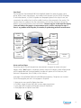
Rear Panel
The rear panel of the Bowman Perfusion Monitor contains a BNC connector for the analog
output, and a 9-pin female connector (DB-9) for serial communications (RS-232) to an outboard
computer. The rear panel also contains the power cord connector and an indicator showing the
power input compatible to the monitor. This is the fuse and line voltage selector. The switch must
be set accordingly for the country of use.
:fj^ediZci^Va
IZgb^cVa
HZg^VaCjbWZg$
GVi^c\hAVWZa
6^g;^aiZg
8dgY$8VWaZ HidgV\Z=dd`h
;jhZVcYA^cZ
KdaiV\ZHZaZXidg
EdaZ8aVbe HZg^Va>$D GH"'('
EdlZg8dccZXidg
6cVad\Djieji
6
Section 2: Monitor Set Up
1. Place monitor on shelf or securely mount on IV pole.
2. Plug power cord into back of monitor and opposite end into wall power outlet. Please note
that the monitor does not have battery capabilities. However, when the monitor is not plugged
into the wall, or is turned off, it will not lose previously recorded data. The monitor will retain
in total 15 days of data.
3. Connect umbilical cord into connector on front left panel of the monitor. The umbilical cord is
12 feet long. Connect the umbilical cord to the properly placed QFlow 500 probe.
4. Press ON/OFF switch on front right panel of the monitor.
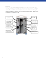
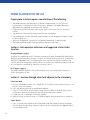
5. The display screen of the monitor should turn on. Message line is on the top of the display
screen.
6. Measurement of tissue temperature and K-value will begin automatically. Correct K value in
brain white matter should be between 4.9 and 5.8.
7. If the probe has been placed correctly in the white matter, perfusion measurement will begin
in 3-5 minutes after the automatic calibration process is completed.
8. Perfusion measurement is displayed in absolute units of ml/100g/min.
9. The graphic display will show perfusion measurement in real time.
Perfusion
Measurement
ml/100g-min
Message Line
Patient Baseline
Temperature
K-VALUE Must be
Between
4.9 and 5.8
Real-time Graphic
Display of Perfusion
Measurement vs. Time.
7
Section 3: Measurement Cycle
The Bowman Perfusion Monitor measurement cycle has three phases: temperature
stabilization, calibration and perfusion measurement. It takes in total about 3-5 minutes on
average for the monitor to go through the temperature stabilization and calibration phases.
During these two phases, no perfusion measurement will be taken. Recalibration happens
automatically at end of the preset perfusion measurement time, which ranges from 2 minutes to
2 hours. The message line at the top of the screen will indicate which phase of the measurement
cycle the monitor is in.
Temperature Stabilization
At the start of each new measurement, the monitor will automatically begin with temperature
stabilization. During this phase, the monitor is confirming the stability of the tissue baseline
temperature, which usually takes several minutes, and no perfusion measurement is taken at
this time. If the patient’s tissue temperature is not stable, or is undergoing dramatic changes, a
warning message will display as “Temp not yet stable – Check Settings – Monitor is trying”; the
monitor will continue to check for temperature stability, and no perfusion measurement will
be taken. Once the tissue temperature is stabilized, the Hemedex CBF Monitoring system will
continue to the calibration phase, followed by measuring perfusion.
Calibration
The calibration for the Bowman Perfusion Monitor and the QFlow 500 probe are done
automatically in-vivo. The monitor automatically calibrates during the period immediately after
temperature stabilization and before perfusion measurement while the probe is implanted in the
target tissue. During calibration, the monitor calculates the thermal conductivity (K) value. The
proper K value for the brain white matter is between 4.9 and 5.8. The monitor has the capability
to automatically re-calibrate within a pre-set time interval ranging every 2 min to 2 hours. The
default setting in the monitor for re-calibration is every 60 minutes. Re-calibration may last 3-5
minutes. During this time, no perfusion measurement is taken. To manually set the Re-Calibration
time interval (for more detail see 6.3.2.2 for Options Menu 2), begin at the Start Menu, press
buttons OPTIONS > MORE OPTIONS > MEASUREMENT CONTROL > PERFUSION PERIOD, then
use arrow keys to adjust time parameters, and press OK to allow the monitor to close out the
dialogue box. This means the monitor will automatically recalibrate at the time interval set for
the perfusion period.
Perfusion Measurement
Perfusion measurement begins after the calibration is complete, but no reading appears until 50
seconds later, when the monitor determines that the measurement is accurate. If the monitor
detects a problem with the measurement results, it automatically re-calibrates, starting a new
temperature stabilization phase to obtain a better reading. During perfusion measurement phase,
the user has the option to choose force calibration by pressing the “Calibration” button, which
initiates the calibration phase immediately. Bowman Perfusion Monitor is capable of detecting
cerebral blood perfusion ranging from 0 to 200 ml/100g/min. To stop perfusion measurement,
simply press the “Stop” button.
8
Section 4: User Interface Menu
Use the menu on the right-hand side of the main screen to control the Bowman Perfusion
Monitor, to set measurement and device parameters, and to manipulate data. A menu shows
up to five options at a time. The menus are arranged in a hierarchical tree, so selection of one
option often opens a new set of menu items at the next level in the tree.
Start / Stop Menu
Start Menu
Start
Stored Data
Options
Print
Stop Menu
Stop
Perf / Cal*
Options
* Perf / Cal
could read
either
“Measure
Perfusion” or
“Calibration”
Print
Start: Starts a perfusion measurement. The measurement cycle always begins with a
temperature stabilization phase.
Stop: Stops a perfusion measurement. This action overrides the measurement control cycle. The
monitor takes a few moments to shut down the measurement process.
Stored Data: Stored Data option allows the user to “review”, “delete”, “upload” or “set the
baud rate for uploading” data. The Bowman Perfusion Monitor saves data automatically with
maximum limit as 15 days of data. The monitor creates a new perfusion file for each probe. If
more than 15 days of data are collected, the additional data will overwrite the first few days
of data for that probe. Data can be uploaded to a computer. For individual data management
support, please contact your local Codman representative. The stored data is identified with three
different tags:
1. The user designated label, which is entered in the Set Label menu.
2. The date of the first use of the probe in the patient. The probe is approved for single-patient
use.
3. The time of the first use of the probe in the patient.
Measure Perfusion: Manually overrides the monitor when it is in the temperature stabilization
phase and initiates a perfusion measurement phase. Measure Perfusion alternates with
Calibrate as the second item in the Stop Menu.
Calibration: Manually overrides the current perfusion measurement phase and initiates a new
measurement cycle of temperature stabilization, calibration, and perfusion measurement.
9
Use the second button in the stop menu as a manual override and initiate temperature
stabilization or perfusion measurement, depending on the state of the instrument. The label of
the button toggles between Measure Perfusion and Calibrate.
Print: Press Print to request printing of data. All printed strips of data include Label information
and the unique probe ID. Select one of the 4 options to print data:
1. Print Perfusion: Print the perfusion trace plot that currently appears in the display screen.
2. Print Perfusion & Temperature: Print plots of perfusion and proximal temperature (patient’s
base line temperature).
3. Print K Values: Print all the values recorded for thermal conductivity and the time and date
they were recorded.
4. Print Settings: Print all the settings currently in place.
Options Menu
Start / Stop
Menu
Options Menu 1
Options Menu 2
Options Menu 3
Options Menu 4
Set Alarm
Service Control
Set Baud Rate
About
View Data
Measurement
Control
Set Data
Frequency
<Blank>
Restore Defaults
Set Date/Time
More Options
More Options
Return
Return
Set Label
Options
More Options
Return
<Blank>
<Blank>
Return
Options Menu 1
Set Alarm: The Bowman Perfusion Monitor includes audio and visual perfusion alarms. When
perfusion drops below the alarm lower bound for a specified period of time, the monitor triggers
the alarm. Similarily, when perfusion rises above the alarm upper bound for a specified period of
time, the monitor triggers the alarm. To enable the alarm:
• Press Audio to turn audio alarm ON or OFF. The speaker symbol on the display screen
brightens or dims.
• Press Visual to turn visual alarm ON or OFF. The siren symbol on the display screen
brightens or dims.
• To set Upper Bound or Lower Bound for perfusion alarm, the user can set the value of
the bound, trigger time and suspend time. Trigger Time specifies how long measured
perfusion must lie outside the bound before the monitor triggers the alarm. Suspend Time
specifies how long a triggered alarm remains suspended (temporarily disabled) after you
acknowledge it. Enable the bound to ensure the activation of the alarm.
• Return three times to get back to the main screen.
10
View Data:
• Press Set Time Range, and use up and down arrow buttons to select the time range of
horizontal axis. The default value is 15 minutes. Use left and right arrow buttons to scroll
the data. Press OK to allow the time range dialog box to close and the plots on the display
screen adjust to reflect the time range of the user’s choice
• Press Scroll Time, and use arrow buttons to select which portion of the data you want to
display.
• Press Set Perfusion Range and use arrow buttons to adjust the upper extend of the
perfusion plot shown on the display screen. Press Autoscale to turn ON or OFF autoscale.
When autoscale is on, the monitor to automatically adjust the displayed plot to allow for the
highest range of perfusion detected.
• Press Select Plots & List K to view various Temperature plots and list of K values.
Set Label: Use arrow keys to select Delete old label if appropriate, or to enter patient name
by pressing O.K. for each selected character. Choose Label Complete when finished. Be sure to
press Return to get back to the main screen.
Options Menu 2
Measurement Control: The Measurement Control Menu allows you adjust the Number of
Cycles; Temp Period and Perfusion Period. See the following chart for the definition and limits
of each parameter. The important option here is Perfusion Period.
11
Press Perfusion Period and use arrow keys to adjust time parameters. Once the time parameters
are set, the monitor will automatically re-calibrate at the interval user set for the perfusion
period. For example, if the time parameter is set at 45 minutes, then the monitor will recalibrate
for every 45 minutes of perfusion period measured. Usually re-calibration takes 3-5 minutes, at
which time no perfusion measurement will be taken. On the display screen, the breaks in the
perfusion vs. time graph represent these re-calibrations.
Recalibration
Period
3-5 minutes
12
Restore Defaults: To restore manufacturer’s defaults, stop all measurements and press Restore
Defaults, and then Confirm Restore. Below is a comprehensive list of default settings, including
the minimum and maximum limits of each parameter.
Setting
Temperature Stability
Time Stability
Number of cycles
Temperature Period
Perfusion Period
Alarm Upper Bound
Alarm Upper Bound Value
Alarm Upper Bound Trigger Time
Alarm Upper Bound Suspend Time
Alarm Lower Bound
Alarm Lower Bound Value
Alarm Lower Bound Trigger Time
Alarm Lower Bound Suspend Time
Baud Rate
Data Frequency
Proximal Temperature Plot
Distal Temperature Plot
Δ Temperature Plot
Time Range
Audio Alarm
Visual Alarm
Perfusion Plot Upper Extent
Minimum
Maximum
Default
0.005°C
10 sec
1
2 min
2 min
N/A
0 ml/100g-min
1 sec
1 min
N/A
0 ml/100g-min
1 sec
1 min
19,200
1 Hz
N/A
N/A
N/A
N/A
N/A
N/A
0.100°C
60 sec
999 or Unlimited
23:59:59
2 hrs
N/A
200 ml/100g-min
30 min
10 min
N/A
200 ml/100g-min
30 min
10 min
115,200
1 Hz
N/A
N/A
N/A
N/A
N/A
N/A
0.025°C
30 sec
Unlimited
2 min
60 min
Disabled
200 ml/100g-min
2 min
10 min
Enabled
0 ml/100g-min
2 min
10 min
115,200
1 Hz
Off
Off
Off
15 min
Enabled
Enabled
10 ml/100g-min
200 ml/100g-min
Autoscale
Options Menu 3
Set Date/Time: Use this option to set the date and time for the monitor.
13
PROBE PLACEMENT IN THE O.R.
Proper probe insertion requires consideration of the following:
• The probe measures focal perfusion in a volume of approximately 0.27ml. This focal
measurement, in absolute units (ml/100mg/min), represents the cerebral blood flow
delivered by the supplying vasculature to that territory.
• Placement should be in the brain white matter, and in the tissue or vascular territory of
interest.
• The probe uses a thermal technique for quantification of perfusion.
• The measurement may be affected by rapid changes in tissue temperature (irrigation, rapid
infusion of fluids, etc.).
• Motion of the probe will cause artifact and possibly recalibration if severe enough.
• The probe should be properly fixed to the bolt or sutured to the scalp.
Section 1: Intra-operative indications and suggested site for Probe
insertion
Aneurysm Repair Surgery
According to the published article “Continuous monitoring of regional cerebral blood flow during
temporary arterial occlusion in aneurysm surgery”, by Thome, Vajkoczy, Horn et al (J. Neurosurg./
Volume 95/September, 2001), the implantation site of the bolt was chosen according to the
vascular territory of interest parasagitally, either 2 cm lateral to the midline for aneurysms of ACD
or 6 cm lateral to the midline for aneurysms of the MCA or ICA.
EC/IC Bypass Surgery
The probe should be inserted in the vascular territory that is most affected by the bypass to
assess the adequacy of flow.
Section 2: Insertion through a burr hole adjacent to the craniotomy
Create Burr Hole
a. At the site for probe insertion, use a scalpel with a #15 blade to make a linear incision 2-3 cm
long and carry it to the bone.
b. Use a self-retaining retractor to provide bone exposure.
c. Using a 2.7 mm drill bit, drill through the outer and inner tables of the skull taking care to
minimize any potential for damage to the dura or the underlying structures.
d. If necessary, use a sterile flush to enhance visibility.
e. Make an incision in the dura using a #11 blade or bipolar, securing hemostasis as necessary.
Create Tunnel
a. Use a 14-gauge Touhy needle to tunnel the probe under the scalp by inserting the needle
from the site of the burr hole, under the scalp to exit at the desired location approximately 6
cm from the burr hole.
14
b. NOTE: The needle cannot slide over the blue connector at the end of the probe.
Therefore, it is necessary to feed the needle from inside the incision site out towards
the exit site.
c. Remove any trocar that may be in the needle lumen.
d. Pass the probe tip through the lumen in the distal end of the Touhy needle and advance the
probe tip toward the burr hole.
e. While holding the probe in place, slide the Tuohy needle out from under the scalp and discard.
Insert Probe
a. Using the blue centimeter markings on the probe shaft as a guide, insert the probe through
the burr hole to a depth of 25 mm below the level of the dura into the white matter.
b. Suture scalp over burr hole as necessary.
c. Loop 4-5 cm of probe slack in a circle around the site where the probe exits from under the
scalp and secure the probe shaft with three sutures spaced evenly apart.
d. Connect the probe to the Bowman Perfusion Monitor. Confirm adequate placement of the
probe by checking the K value. Normal range for K value in brain white matter is between 4.9
and 5.8.
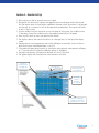
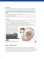
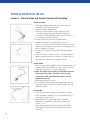
Figure 1 below is a graphic depiction of
the placement of the probe though a burr
hole adjacent to the craniotomy. In the
event that post-operative monitoring is
desired, it is best to forward tunnel the
probe.
Figure 1: Drawing of the QFlow 500 Probe
placed via a burr hole and tunneled adjacent
to a craniotomy.
Section 3: Insertion Through
the Craniotomy
Based on neurosurgeon preference, the intra-operative placement of the probe through a
burr hole may not be desirable. In this case, the probe may still be placed through an open
craniotomy. However, extra care must be taken to position the probe at the edge of the
craniotomy away from the main surgery site to minimize artifact from retraction, irrigation and
mechanical interference.
The figure below shows a rendition of the placement of the probe though the craniotomy. In
the event that post-operative monitoring is desired, it is best to forward tunnel the probe. Also
make sure to insert the probe through the site of one of the burr holes that was used to create
the craniotomy. In this way, when the bone flap is put back in place, there will be an opening for
the probe shaft to exit. The procedural steps for the probe placement through a craniotomy with
tunneling are as follows:
15
Create Tunnel
Use a 14-gauge Touhy needle to tunnel the probe under the scalp by inserting the needle from
the edge of the craniotomy, under the scalp to exit at the desired location approximately 6 cm
away. NOTE: The needle cannot slide over the blue connector at the end of the probe.
Therefore, it is necessary to feed the needle from inside the incision site out towards the
exit site.
a.Remove any trocar that may be in the needle lumen.
b.Pass the probe tip through the lumen in the distal end of the Tuohy needle and advance the
probe tip toward the craniotomy.
c.While holding the probe in place, slide the Tuohy needle out from under the scalp and discard.
Insert Probe
d.Using the blue centimeter markings on the probe shaft as a guide, insert the probe to a depth
of 25 mm below the level of the dura into the white matter.
e.Loop 4-5 cm of probe slack in a circle around the site where the probe exits from under the
scalp and secure the probe shaft with three sutures spaced evenly apart.
f. Connect the probe to the Bowman Perfusion Monitor via the umbilical cord. Once the
probe is properly connected to the Bowman Perfusion Monitor, power on the monitor. The
monitor will automatically calibrate the
implanted probe through checking for
temperature stabilization and K value.
Confirm adequate placement of the
probe by checking the K value. Normal
range for K value in brain white matter
is between 4.9 and 5.8. NOTE: Do
not break the sterile environment
without confirming the proper K
Value. If K value is not within the
normal range, please check the
Troubleshooting Guide section of this
manual.
Figure 2: The placement of the QFlow 500
Probe placed via craniotomy and tunneled.
Section 4: Confirm K Value
Confirm adequate placement of the probe by checking the K Value. Connect the probe to the
umbilical cord and Monitor and the measurement will automatically begin. After about 3 minutes,
the Monitor will go into calibration and display a K Value. Normal range for K value in brain white
matter is between 4.9 and 5.8. If the K value is out of range, an error message will appear on top
of the display screen. The monitor will not deliver cerebral blood flow measurements.
16
a.If you have a high K Value (>5.8), move the probe 1 mm by either advancing or retract it.
b.The monitor will automatically try to recalibrate. However, if Temperature Stabilization Phase is
taking too long, press “Measure Perfusion” to request an earlier calibration.
c.After confirming placement with a good K Value (4.9 <= K <= 5.8), allow the measurement to
continue and fix the probe.
Section 5: Potential Sources of Interference
During intra-operative procedures, the measurement of perfusion may be affected by:
• Thermal instability from tissue cooling via the open craniotomy;
• Thermal instability from fluid irrigation;
• Probe motion from tissue retraction;
• Reduced perfusion from tissue compression via retraction;
• Probe motion from external interference;
• Electrocautery, especially unipolar (Bovie).
Based on these considerations, it is recommended that the probe be inserted though a burr hole
just adjacent to the craniotomy to reduce thermal and mechanical interference to the probe.
Irrigation
Tissue irrigation close to the entry location of the probe may cause thermal instability in the
reading and prevent an accurate measurement of blood flow and/or induce a longer stabilization
time.
Retraction
Retraction can affect the measurement by 1) inducing the cerebral tissue to move relative to the
probe, thus causing a motion artifact; and 2) by decreasing the blood flow by compression of the
tissue behind the retractor. Therefore it is suggested that the probe be placed away from the site
of retraction.
Electrocautery
Electrocautery, both unipolar (Bovie) and bipolar, can cause electrical interference with the
Monitor. This interference can introduce noise into the perfusion data and possibly cause the
monitor to automatically recalibrate. The operation of the device should return to normal, as soon
as the electrocautery ceases.
Probe movement
Probe movement may be caused by retraction or by external interference with the probe shaft.
Linear movement of the probe along the insertion track causes a characteristic artifactual spike
in the perfusion measurement. This is recognized by the Monitor which then produces an error
message. If the motion is significant enough, the monitor will automatically recalibrate.
17
PROBE PLACEMENT IN THE ICU
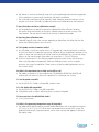
Section 1: Probe Insertion and Fixation Protocol with Tunneling
Create burr hole
a.Shave and prep the determined site and exit area (for
tunneling) using aseptic technique.
b.Drape the shaved, prepped area.
c. Mark the incision site with a marking pen and ruler.
• Consider injecting the area with a local anesthetic.
• Use the #15 blade/scalpel to make a linear incision 2 – 3
cm long and carried to the bone.
d.Use the self-retaining retractor to expose bone
e.Prepare drill according to manufacture’s instruction.
f. Using a 2.7 mm twist drill, drill through the outer and inner
tables of the skull taking care to prevent any damage to the
dura or underlying structures.
g.If necessary, use sterile saline to flush the site for better
visibility.
h.Make an incision in the dura using a # 11 blade/scalpel or
bipolar, securing hemostasis as necessary. Visually confirm
that there are no obstructions to probe insertion.
Create tunnel
a.Use a 14 gauge Tuohy needle to tunnel the probe under the
scalp by inserting the needle into incision site and moving
under the scalp to exit 6 cm from scalp incision.
b.NOTE: The needle can not slide over the blue connector
at the end of the probe. Therefore, it is necessary
to feed the needle from inside the incision site out
towards the exit site.
c. Remove and discard any trocar.
d.Pass the Probe tip into distal end of needle (exit site) and
out proximal end (incision site); slide the needle from the
Probe and discard.
Insert probe
a.Using the centimeter markings on the Probe as a guide,
insert the Probe to a depth of 25 mm subdurally into the
target (white matter) tissue.
b.Before breaking the sterile field, confirm adequate
placement of the probe by checking the K Value (see
Section 5.2.2.3).
c. After confirming placement with a good K Value, allow
measurement to continue and suture dura and scalp as
necessary.
18
d.Clean and dry the Probe site.
e.If desired, attach the Hemedex Fixation Disk.
• If desired, attach the probe shaft to the scalp using the
Hemedex Fixation Disk.
• Position the disk onto the Probe via the slit (as described
in the Disk instructions for use).
• Slide the Disk onto the scalp and secure Disk in place
with sutures.
• Close the clamp completely, ensuring that the Probe is
still adequately positioned (25 mm deep, subdurally).
• If necessary, apply adhesive dressing.
f.Loop 4-5 cm of probe slack in a circle
around the probe exit site and secure
shaft to scalp with three (3) sutures
spaced evenly apart.
g.Apply appropriate dressing to burr hole
and probe exit site.
h.If appropriate, tape the blue probe
connector to the patient’s neck or shoulder
to minimize movement.
i. Be sure to position the umbilical cord in
such a fashion to prevent accidents and
minimize movement.
Figure 4: Insertion of the QFlow 500 Perfusion
Probe via a burr hole and tunneled
Section 2: Probe Insertion and Fixation Protocol with Bolt
Create burr hole
a.Shave, prep, and drape the insertion site using aseptic
technique.
b.Mark the insertion site with a marking pen and ruler.
c.Consider injecting the area with a local anesthetic.
d.Use the #15 blade/scalpel to make a linear incision 2 – 3
cm long and carried to the bone.
e.Use the self-retaining retractor to provide bone exposure.
f. Prepare drill according to manufacturer’s instruction.
g.Drill through the outer and inner tables of the skull taking
care to minimize any potential for damage to the dura or
underlying structures.
h.If necessary, use sterile saline to flush the site for better
visibility.
19
i. Make a cruciate incision, in the dura using a # 11 blade/scalpel or bipolar, securing hemostasis
as necessary. If the opening in the dura is not sufficient, the probe will not properly track into
the cerebral tissue.
j. Visually confirm that there are no obstructions to probe insertion on the tissue surface.
Insert the cranial bolt
Follow manufacturer’s instructions. Be sure to attach the
compression cap for the QFlow 500 Probe.
Insert probe
a. Remove QFlow 500 Probe from package. Be sure to mark
the probe for adequate depth insertion.
b. Feed the Probe through the corresponding port of the bolt,
being careful not to bend the rigid tip of the Probe.
c. Using the centimeter markings on the Probe, glide the
Probe to a depth of 25 mm subdurally into the target
(white matter) tissue. Make sure to account for any space
left between the end of the bolt and the dura.
d. Before breaking the sterile field, confirm adequate
placement of the probe by checking the K Value. See
Section 5.2.2.3 for instructions.
e. Secure the bolt locking mechanism as described by bolt
manufacturer.
Figure 5: Drawing of the
QFlow 500 Perfusion Probe
fixed with a cranial bolt
Section 3: Confirm K Value
Before breaking the sterile field, confirm adequate
placement of the probe by checking the K Value. The K
value for white matter should be 4.9 to 5.8 mW/cm-C. Connect the probe to the umbilical cord
and Monitor and the measurement will automatically start. After a few minutes, the Monitor will
go into calibration and display a K Value. If the probe is not in a good location you will receive an
error message on the top of the display screen. If you have a high K Value (>5.8):
• Move the probe 1 mm by either pulling it back or advancing it.
• The monitor will automatically try to recalibrate. However, if Temperature Stabilization Phase is
taking too long, press “Measure Perfusion” to request calibration earlier.
• After confirming placement with a good K Value, allow the measurement to continue and fix
the probe to the bolt or the dressing; cover with tape.
20
• If appropriate, tape the blue probe connector to the patient’s neck or shoulder to minimize
movement.
• Position the umbilical cord in such a fashion as to prevent dislodgment and minimize
movement.
Section 4: Potential Sources of Interference
Fever
The Bowman Perfusion Monitor automatically suspends measuring perfusion when the
tissue temperature reaches 39.5 °C or above. Perfusion measurement is automatically resumed
when the tissue temperature drops below this level. The device is designed to operate in this
way because the FDA mandates that tissue must not be heated above 41 °C. The probe will
not heat the tissue when patient’s baseline temperature reaches 39.5 °C, and the monitor will
automatically stop measurement.
Rapidly changing temperature
The probe does contain a reference temperature sensor that permits the monitor to compensate
the signal for changes in patient temperature. During calibration period, the probe will start
measurement when the tissue temperature environment has been stable for a period of
2 minutes. If temperature stable environment is not detected, the monitor will continue to
recalibrate and not able to deliver cerebral blood flow measurement.
Probe movement
Probe motion causes an artifact in the measurement with an apparent and characteristic spike
upward in perfusion measurement. This is caused by the fact that the distal sensor must rapidly
re-establish the thermal field in the tissue at the site where the sensor has been translated
to. If the perfusion measurement does not return to the pre-motion level, the monitor will
automatically recalibrate.
21
FREQUENTLY ASKED QUESTIONS (FAQs)
1.How do you insert the Monitor’s QFlow 500 Probe?
a. Similar to other cerebral probes, e.g. intraparenchymal ICP probes, which are inserted via a
burr hole.
b.The probes can also be tunneled under the scalp.
c. For full details see Section 5.1 and 5.2.
2.Where do you implant the probe?
a.The probe should be placed in the vascular territory at risk for ischemia, or in the area of
interest for measuring CBF.
b.The probe tip should be completely surrounded by white matter.
3.What risks are there in implanting the Probe?
a. Same as implanting other minimally invasive, intraparenchymal probes.
b. Contraindications are the same as catheter insertion into tissue.
c. Histological studies reveal only minimal tissue destruction, and no bleeding around insertion
track.
d.There have been no signs of inflammation, edema, or thermal damage (tissue temperature is
never heated above 41 ˚C (105.8 ˚F), as mandated by the FDA.
4.At what depth is the probe tip placed?
a.The probe tip should be placed approximately 20-25 mm below the dura in the white matter
of the brain.
5.How do I know I have the probe tip in a good location?
a. Good placement is determined by the K Value. Normal range for K value in the brain white
matter is between 4.9 and 5.8. If your K Value is too high, the probe tip may be next to a
thermally significant vessel which flow is confounding the measurement or the brain may be
periodically moving against the probe from the cardiac cycle.
b.If the K Value is not in the suggested range, the Monitor will alert the user. It is for this reason
you should check your K Value prior to securing the probe in place or breaking sterile field. To
obtain a good K Value, move the probe by either advancing it or pulling it back 1 mm.
c.Another way to ensure proper depth placement is with a CT scan. The probe is radio-opaque
and, although you will not be able to see the depth markings, you will be able to see the
probe tip.
6.What are the technique sensitivities of the QFlow 500 Probe?
a.The probe will calibrate itself by measuring tissue temperature and conductivity (K) prior to
measuring perfusion. This process typically lasts a few minutes (approximately 4 minutes
depending on the level of perfusion).
b.If the probe is moved, it will automatically recalibrate itself.
c. Placing the probe near a thermally significant vessel will give a high K Value.
d.During recalibration you cannot obtain perfusion measurements. Recalibration will be
performed after 30 minutes (unless the default settings are changed), and will be done
automatically.
22
e.The Monitor is sensitive to electrical noise such as that produced by electrocautery equipment.
If the interference is great enough the Monitor will need to recalibrate.
f.The tissue being measured must be thermally stable; therefore, external influences such as
irrigation may cause a thermally unstable environment and inhibit perfusion measurement.
7. Does the Probe need to be calibrated or zeroed?
a.No, the probe does not need to be zeroed or calibrated like other catheters. However,
the monitor does automatically go through a calibration phase to ensure accuracy of the
measurement. The user does not need to do anything to calibrate the probe.
8. How long does Calibration take?
a. Calibration typically takes a few minutes depending on blood flow; the higher the flow the
quicker the calibration process and vice versa.
9. Is the probe sensitive to motion artifact?
a. Yes, the probe is sensitive to motion artifact. If the probe tip is moved significantly in relation
to the tissue where it’s implanted, the monitor will be forced into recalibration. However, if the
motion is minor then the monitor will not be forced into recalibration but, you will see sharp
spikes in on the monitor graph; these spikes can range from 0 – 250 ml/100g-min.
b.In the ICU environment it is less likely to experience motion artifact than in the OR setting.
When using the probe intra-operatively there are challenging factors such as irrigation,
retraction, and surgical manipulation. These factors may lead to probe displacement and, in
turn, motion artifact.
10. What is the maximum time a Probe can be left in situ?
a.The probe is indicated for 10 days implantation. The Bowman Perfusion Monitor will
automatically not record any data from a probe that is used longer than 20 days.
11. Are the probes reusable?
a.No, the QFlow 500 Probe is a disposable, single-use item.
12. Is the Probe MRI compatible?
a.No, the QFlow 500 Probe is not MRI compatible.
b.If the patient needs an MRI, it will be necessary to remove the probe.
13. How sensitive is the QFlow 500 Probe?
a. 0.1 ml/100g-minute.
14. What is the operating temperature range of the probe?
a.The probe will be able to measure accurate cerebral blood flow with in temperature range of
20°C (68°F) to 39.5°C (103.1°F). When the tissue temperature is outside of this range, the
probe will automatically stop measurement, and an error message will appear on the top of
the display screen.
23
15. Can the Monitor accommodate more than one probe?
a.The monitor is a single channel device. If you want to simultaneously monitor more than
one QFlow 500 Probe you will need additional Monitors. Alternatively, 2 Probes could be
intermittently measured with a single Monitor.
16. Can the Bowman Perfusion Monitor interface with other patient monitors?
a.The Monitor provides both analog and digital outputs which can be interfaced with other
patient monitors and data acquisition systems by the user.
b.Digital data is streamed through a serial port and can be uploaded to a laptop.
c.The analog output can be connected to a Philips bedside monitor with an Open Link module.
Contact your local Codman representative for assistance.
17. Does the Monitor have alarms?
a. Yes, the Monitor can be set to alarm if the perfusion reaches above or below a certain
threshold for a user-defined time period (i.e., a quick “spike” above or below the alarm
thresholds will not set off the alarm). The Alarms are not enabled by default; the user needs
to enable the alarms and set the bounds.
18. How much data can be stored/retrieved?
a.The monitor can collect data at a rate of once a second and there is enough memory to store
this data for 15 days.
19. Can you print a trend or just the numerical values?
a. You have the option to print the following 4 items:
• Print perfusion, i.e., what you see on the monitor graph
• Print perfusion and temperature (on the same strip)
• Print a list of the K Values
• Print the current Monitor settings
20. Can the data be smoothed?
a.No, at this point in time the data cannot be smoothed. However, the time range can be
adjusted so that the data can be spread out over time, which allows for more detailed viewing
at specific points in time.
21. Can the average or mean be displayed or printed?
a.No, the monitor gives perfusion measurements in real time only and, currently, does not have
the capability to display a mean or average CBF measurement.
b. However, if you printout the data it is easier to see what the average value was for the last 30
minutes perfusion run.
22. What other limitations are present?
a.The Monitor will not heat tissue above 41 ˚C (105.8 ˚F); therefore, if a patient has a
temperature around 39.5 ˚C (103.1 ˚F) the Monitor will not be able to measure cerebral blood
flow. Once the patient’s temperature is below this threshold, the Monitor will automatically
start measuring again.
24
b.The measurement is focal in nature; specifically, the probe measures cerebral blood flow in
the small, spherical volume of tissue surrounding the distal tip of the probe, a sphere of tissue
about 4-5 mm in diameter, approximately equivalent to a volume of 0.27ml.
TROUBLESHOOTING GUIDE
Measurement Step
Possible Problems
Possible Causes
Possible Solutions
Insert Probe
Start Measurement
Temperature not stable
Probe recently inserted
Wait 10 minutes
Probe not deep enough
Verify probe is at proper depth (25
mm subdural)
Probe not deep enough
Verify probe is at proper depth
o Probe is epidural
Confirm probe location with CT
When patient temperature goes
below 39.5°C, CBF measurement
will automatically restart
Temperature
Stabilization
Thermal gradient too high
o Probe is not in white matter
Patient temperature too high
Fever above 39.5 °C
Probe pulled out of tissue
(K<1.5)
Low Km (<4.8)
Calibration
o High Km (>5.8)
o Data too noisy
www.hemedex.com
1-866-HEMEDEX
Measurement Step
36
Possible Problems
Verify probe is in tissue at proper
depth (25 mm subdural)
Probe is not in white matter
Confirm probe location with CT
Probe motion or electrocautery
Recalibrate
o Probe may be too deep
o Probe may be in the ventricle
o Probe may be sub/epidural
o Verify probe tip is at proper depth
(25 mm subdural)
o Confirm probe location with CT
Probe may be near a vessel
Move the probe about 1mm along
the insertion track
H44000015, Revision A
Possible Causes
Possible Solutions
Probe may be in gray matter
CBF < 10 ml/min-100 g
Probe may be in infarcted tissue
CBF varies ±10 ml/min-100g
with respiration rate and/or
heart rate
CBF varies ±10 ml/min-100g
over minute(s)
CBF drift
o Probe may be too deep
o Probe may be in the ventricle
o Probe may be epidural
Slow variations may be due to
reduced autoregulation
Temperature is rapidly changing
Motion artifact
Probe has moved
Temperature drift
Temperature is rapidly changing
CBF > 50 ml/min-100g
CBF measurement
o Verify probe is at proper depth
o Confirm probe location with CT
o Verify probe is at proper depth (25
mm subdural)
o Confirm probe location with CT
Compare CBF variations with ICP,
CPP and MAP variations
Manually recalibrate
Recalibration
Make sure probe is secured and at
correct depth
Monitor automatically recalibrates
25
REFERENCES
Clausen T, Scharf A, Menzel M, Soukup J, Holz C, Rieger A, Hanisch F, Brath E, Nemeth N, Miko I,
Vajkoczy P, Radke J, Henze D., “Influence of moderate and profound hyperventilation on cerebral
blood flow, oxygenation and metabolism”, Brain Research; Sep 3; 1019(1-2):113-23, 2004.
J.C. Hemphill, M.M. Knudson, N. Derugin, D. Morabito, and G.T. Manley, “Carbon dioxide reactivity
and pressure autoregulation of brain tissue oxygen,” Neurosurgery, 48(2):377-384, 2001.
P. Horn, P. Vajkoczy, C. Thomé, M. Quintel, H. Roth, L. Schilling, P. Schmiedek, “Effects of 30%
stable xenon on regional cerebral blood flow in patients with intracranial pathology,” Keio Journal
of Medicine, 49(1): A161-163, 2000.
Jaeger M, Soehle M, Schuhmann MU, Winkler D, Meixensberger J., “Correlation of continuously
monitored regional cerebral blood flow and brain tissue oxygen”, Acta Neurochir (Wien); Jan;
147(1):51-6; 2005.
Muench E, Bauhuf C, Roth H, Horn P, Phillips M, Marquetant N, Quintel M, Vajkoczy P., “Effects of
positive end-expiratory pressure on regional cerebral blood flow, intracranial pressure, and brain
tissue oxygenation”, Critical Care Medicine; 33(10):2367-72, 2005.
C. Thomé, P. Vajkoczy, P. Horn, C. Bauhuf, U. Hübner, and P. Schmiedek, “Continuous monitoring of
regional cerebral blood flow during temporary arterial occlusion in aneurysm surgery,” Journal of
Neurosurgery, 95(3):402-411, 2001.
P. Vajkoczy, U. Hubner, P. Horn, C. Bauhuf, C. Thome, L. Schilling, and P. Schmiedek, “Intrathecal
sodium nitroprusside improves cerebral blood flow and oxygenation in refractory cerebral
vasospasm and ischemia in humans,” Letter to the Editor, Stroke, 31:1195-1197, 2000.
P. Vajkoczy, H. Roth, P. Horn, T. Luecke, C. Thomé, U. Huebner, G.T. Martin, C. Zappletal,
E. Klar, L. Schilling, and P. Schmiedek, “Continuous monitoring of regional cerebral blood
flow—Experimental and clinical validation of a novel thermal diffusion microprobe,” Journal of
Neurosurgery, 93:265-274, 2000.
P. Vajkoczy, P. Horn, C. Thomé, E. Munch, and P. Schmiedek “Regional cerebral blood flow
monitoring in the diagnosis of delayed ischemia following aneurismal subarachnoid
hemorrhage,” Journal of Neurosurgery, 98:1227-1234, 2003.1
26
325 Paramount Drive · Raynham, MA 02767 · www.codman.com
Hemedex Neurosurgery products are distributed by Codman.
For more information, contact your Codman Sales Representative.
For Product information, call 800.225.0460.
HEMEDEX® is a registered trademark of Hemedex, Inc.
© 2007 Codman & Shurtleff, Inc. All rights reserved. MON-32-000 12/07 LKS/UM