1
US008538560B2
(12) United States Patent
(10) Patent N0.:
(45) Date of Patent:
Brown et a].
(54)
WIRELESS POWER AND COMMUNICATION
UNIT FOR PROCESS FIELD DEVICES
(58)
US 8,538,560 B2
Sep. 17, 2013
Field of Classi?cation Search
CPC ........................................... .. G05B 2219/31472
USPC ................ .. 700/19, 17, 83, 20, 22; 713/320,
713/330; 455/76.11, 343.1, 574, 67.11
See application ?le for complete search history.
(75) Inventors: Gregory Brown, Chanhassen, MN (US);
George Hausler, Maple Grove, MN
(US); Philip Ostby, Cologne, MN (US);
Robert Karschnia, Chaska, MN (US);
Richard Nelson, Chanhassen, MN (US);
(56)
References Cited
U.S. PATENT DOCUMENTS
Mark Fandrey, Eden Prairie, MN (US)
2,640,667 A
6/1953
Winn ............................ .. 248/65
2,883,489 A
4/1959
Eadie, Jr. et al. ........... .. 335/148
(Continued)
(73) Assignee: Rosemount Inc., Eden Prairie, MN (US)
(*)
Notice:
Subject to any disclaimer, the term of this
patent is extended or adjusted under 35
FOREIGN PATENT DOCUMENTS
CH
CN
672 368 A5
06 199284 A
ll/l989
7/1994
(Continued)
U.S.C. 154(b) by 1651 days.
OTHER PUBLICATIONS
(21) Appl. N0.: 10/850,828
USA & Metric Thread Standards http://www.carr1ane.com/Cata10g/
index.cfm/29425071FOB221118070C1C513906103EOB05543
(22) Filed:
BOB012009083C3B285357474A2D020609090C0015312A36515
F554A5B.*
May 21, 2004
(65)
(Continued)
Prior Publication Data
Primary Examiner * Kavita Padmanabhan
US 2005/0245291 A1
Nov. 3, 2005
Assistant Examiner * Darrin Dunn
(74) Attorney, Agent, or Firm * Westman, Champlin &
Related US. Application Data
(63) Continuation-in-part of application No. 29/204,502,
(51)
(57)
ABSTRACT
?led on Apr. 29, 2005, now Pat. No. Des. 528,020.
A wireless power and communication unit for ?eld devices is
con?gured to connect to a ?eld device and provide operating
power and wired digital communication between the unit and
Int. Cl.
the ?eld device. RF circuitry in the unit is con?gured for radio
frequency communication. In one embodiment, power sup
G05B 11/01
G05B 15/00
H04B 17/00
H04B 1/16
H04B 1/38
G06F 1/26
(52)
Kelly, P.A.
(2006.01)
(2006.01)
(2006.01)
(2006.01)
(2006.01)
(2006.01)
ply circuitry in the unit includes one or more solar power cells
that convert solar energy into electricity to power both the unit
and the ?eld device. The unit interacts with the ?eld device in
accordance with a standard industry communication proto
col. The unit communicates wirelessly with an external
device, such as a control room, based upon the interaction
US. Cl.
with the ?eld device.
USPC ............ .. 700/22; 700/19; 700/83; 455/67.11;
455/343.1; 455/574; 713/320
31 Claims, 9 Drawing Sheets
US 8,538,560 B2
Page 2
(56)
References Cited
5,954,526 A
9/1999 Smith ......................... .. 439/136
5,957,727 A
9/1999 Page, Jr.
5,978,658 A
U'S' PATENT DOCUMENTS
3,229,759 A
3,232,712 A
3,568,762 A
1/1966
2/1966
3/1971
Grover et a1. ............... .. 165/105
Stearns ..... ..
23/255
Harbaugh
. 165/105
3,612,851 A
10/1971 Fowler
3,631,264 A
12/1971
11/1999
439/607.58
Shoji ................... .. 455/66
6,013,204 A
1/2000 Kanatzidis et a1. ......... .. 252/584
6,079,276 A
6,104,759 A
6,109,979 A
6/2000
8/2000
8/2000
Fricket a1. ...................... .. 73/18
Carkneretal. .
375/295
Garnett ...... ..
.. 439/709
362/30
6,126,327 A
10/2000 Bi et al.
Morgan ...................... .. 327/309
6,127,739 A
10/2000 Appa
11/2000 Ferry etal.
709/221
.. 290/55
3,633,053 A
1/1972 Peters
6,150,798 A
D225,743 S
3,881,962 A
1/1973 Seltzer ....................... .. BIO/102
5/1975 Rubinstein
136/209
6,255,010 B1
6,282,247 B1
7/2001
8/2001
3,885,432 A
5/1975
Herzl ..... ..
73/86122
6,295,875 B1
10/2001
Fricket a1. .................... .. 73/718
3,931,532
1/1976
Byrd
. . . ..
6,312,617
11/2001
Kanatzidisetal.
A
4,005,319 A
4,042,757 A
...........
1/1977 Nilsson etal.
8/1977 Jones ........ ..
4,063,349 A
12/1977
4,084,155 A
4,116,060 A
4,125,122 A
4,322,724 A
310/4
.. 310/83
. 429/104
Passler et a1.
B1
6,326,764 B1
6,338,283 B1
.. 429/30
375/285
........ ..
252/62.3
12/2001 Virtneles ..................... .. 320/101
1/2002 Blazquez Navarro
.... .. 29/627
et 31, ,,,,,,,,,,,,,,,,,,,,,,,,,, ,, 73/8658
4/1978 Herzl etal. ............ ~ 340/87039
6,360,277 B1
9/1978
Frederick .............. ..
323/273
George et a1.
Shen .......... ..
3/2002
Ruckley et a1. ............. .. 709/250
73/86122
6,385,972 B1
5/2002
Fellows ........ ..
ll/l978 Stachlrrskl ~
136/205
6,405,139 B1
6/2002
Kicinski etal.
.... .. 702/33
.. 60/517
3/1982 Grulerlskl ~
~ 340/595
6,441,747 B1
8/2002 Khairetal. ..
340/870.16
4,361,045 A
ll/l982 Iwesakr
73/654
6,457,367 B1
10/2002 Behm etal. ..
.. 73/753
4,370,890 A
2/1983 Frrck
73/718
6,480,699 B1
11/2002 Lovoi
4,383,801 A
4,389,895 A
5/1983
6/1983
416/17
6,508,131 B2
4,390,321 A
6/1983 Langlorsetal
Pryor
Ruchlr; ~~~~~ ~
1/2003
455/41.2
Frick ............. ..
73/724
6,574,515 B1
6/2003 Kirkpatrick etal.
417/15
6,640,308 B1
10/2003 Keyghobadetal.
.. 700/19
713/300
4,475,047 A
10/1984
Ebert, Jr. ....................... ~ 307/66
6,661,220 B1
12/2003
4,476,853 A *
10/1984 Arbogast .................... .~ 126/578
6,667,594 B2
12/2003 Chian
4,485,670 A
12/1984 Carnarda etal
73/179
6,690,182 B2
2/2004 Kelly etal.
307/66
6,711,446 B2
3/2004
6/2004 Gerlach etal. ......... .. 340/870.21
4,510,400 A
4/1985
4,570,217 A
2/1986 Allen etal
4,590,466 A
5/1986 Wiklund et a1.
4,637,020 A
1/1987 Schinabeck
4,639,542 A
Krteley ~~~~~~~~ ~~
1/1987 Bassetal
Glehr ............ ..
.. 73/756
324/207.17
318/696
324/700
Kirkpatrick etal. .......... .. 700/19
700/19
6,747,573 B1
.. 340/87028
6,774,314 132
3/2004
714/736
6,778,100 B2
8/2004 Schempf
Hilleary ,,,,, H
136/210
6,792,259 B1
9/2004
4,704,607 A
11/1987 Teather et a1.
340/825.07
6,794,067 B1
9/2004 Acker et 31, ,
4,749,993 A
6/1988 Szabo et a1.
340/870.31
6,823,072 B1
4,860,232 A
4,878,012 A
8/1989 Lee et al.
10/1989 Schulte etal
.. 364/57104
324/60
6,833,359 132
6,839,546 B2
1/2005 Shah
H 322/33
1/2005 Hedtke .................... .. 455/67.11
4,977,480 A
12/1990 Nishihara
73/724
6,839,790 B2
1/2005 BarrosDeAlmeida
6,843,110 132
1/2005
363/26
6,891,477 B2
5/2005
340/606
361/56
. 320/101
6,891,838 B1
6,904,295 B2
5/2005
6/2005
Petite et a1. ................. .. 370/401
Yang ,,,,,,,,,,,,,,,,,,,,,,,,,,, n 455/522
. 343/792
6,907,383 B2
6/2005 Eryurek etal
~~ 73/718
6,910,332 B2
6/2005
4,982,412 A
1/1991
Gross .............................. .. 377/6
5,009,311 A
4/1991
$911er ~~~~~~~~~~~~~~~~~~~~~~~ ~~ 206/332
5,014,176 A
5/1991 Kelleher et a1.
5,023,746 A
5,025,202 A
60991
6/1991
Epsleln ~~~~~ ~
Ishllet a1.
5,079,562 A
1/1992 Yarsunas et a1.
5,094,109 A
30992
D9111} etal~ ~~
133311370 5
12/1992 Wllllams
5,170,671 A
12/1992 Mlau et a1.
Parise .... ..
,, 340/87007
.. 340/870.07
11/2004 Hoover
et 31,
429/408
381/7
,,,,,,,,,,,,,,,,,,,,,,,,,,, ,, 710/305
, 73/114,35
Fellows ..... ..
~ 1310/46
6,942,728 B2
9/2005 (:aillatetal
73/861.22
6,984,899 B1
1/2006
5,223,763 A
60993 Chang ~~~~~~~~~~~~~~~~~~~~~~~~~ ~~ 310/339
6,995,677 B2
2/2006 Aronstain etal
1345407 S
30994
6,995,685 B2
2/2006
Wllllams ~~~~~~~~~~~~~~~~~~~~~ ~~ 1310/46
. 455/343.1
Rice ,,,,,,,,,,,,,, U
Randall ......... ..
702/183
.. 60/520
117/3
H 290/44
340/606
340/870.39
5,313,831 A
50994 Béckman
~~
73/20414
7,010,294 B1
3/2006 Pyotsiaetal.
5,329,818 A
70994 Frlck etal~ ~~
73/708
7,036,983 B2
5/2006 Green etal.
374/179
5412535 A
50995
~ 361/700
7,043,250 B1
5/2006
455/445
(3119084111 ~~
54951769 A
30996 Broden etal
5506757 A
40996
5,531,936 A
7/1996 Kanat21dls et a1.
5,554,809 A
9/1996 Tobita Gt £11.
5554922 A
DeMartino ..
455/420
73/18
7,058,542 B2
6/2006 Hauhia etal.
~ 361/796
7,073,394 B2
7/2006
. 252/587
7,116,036 B2
10/2006 Balasubramaniam
90996 Kunke1_ ~~~~~~~~~~~~~~~~~~~~~~~~~~~ ~~ 32%
7,136,725 B1
11/2006 Paciorek etal.
5,606,513 A
2/1997 Louwagle et a1. .......... .. 702/138
7173343 B2
2/2007
5,618,471 A
4/1997 Kanmidis @131
~ 252/582
7:233:745 B2
6/2007 Loeeniie'i'fIIIIIIIIIIIIIIIIIIII. 398/128
5,637,802 A
5642301 A
60997 FncketaL ~~~~~~~~~~~~~ ~~ 73/724
6/1997 Wernoretal
~~ 364/57102
7,262,693 B2
7,271,679 B2
Brorby_~_ ~~~~~~~~~~~ ~~
73/700
et a1, ““““““““““““““ u 310/322
Kugel ““““ H
8/2007 Karehnia et al.
9/2007 Lundberg etal.
11/2007 Seyfang etal. .
5,644,185 A
70997 Mlller ~~~~~~~~~~ ~~
310/306
7,301,454 B2
5,656,782 A
8/1997 Powell, 11 etal.
73/756
7319191 B2
1,2008 POOH etal,
5,665,899 A
9/1997 WillCOX ........... ..
731/163
7,329,959 B2
2/2008
5705978 A
10998 Prick etal~
~ 340/511
7:539:593 B2
5,722,249 A
5,726,846 A
3/1998 Millenlr
62/2382
3/1998 Houbre ~~~~~~~~~~~~~~~~~~~~~~~~~ ~~ 361/93
7,560,907 B2
7,626,141 B2
5,764,891 A
*
6/1998
8/1998 Tapperson et al
5,803,604 A
9/1998
5,811,201 A
Pompei ........ ..
290/1R
340/508
.... .. 333/24
340/539.26
174/5062
“““ n 290/2
5/2009 Machacek
702/127
7/2009 Nelson .......................... .. 322/37
12/2009 Rodriguez-Medina
etal,
,,,,,,,,,,,,,,,,,,,,,,,,,,, ,, 219/260
395/200.31
7,726,017 B2
6/2010 Evans et a1, ,,
374/181
7,983,049 B2
7/2011
,, 29/854
Leifer et a1. ................ .. 361/728
429/17
8,005,514 B2
8/2011
Saito etal. .................. .. 455/572
Palan ........ ..
. 403/337
8,150,462 B2
4/2012
Gnenteretal. .
455/557
5,870,695 A
5,872,494 A
2/1999 Brown etal.
2/1999 Palan etal. .
. 702/138
. 333/252
2001/0025349 A1
2002/0029130 A1
9/2001 Sharood etal. .
3/2002 Eryurek etal. .
713/340
702/183
5,899,962 A
5,929,372 A
5/1999
7/1999
Louwagie etal. .
. 702/138
Oudoire etal. ............. .. 136/208
2002/0065631 A1
2002/0095520 A1
5/2002
7/2002
5,851,083 A
9/1998 Skowronski
700/295
Kim et 31‘
Warrior ......................... .. 710/72
5,793,963 A
702/183
Foster ...................... .. 73/861.22
12/1998
Loechner ...... ..
702/188
Wettstein etal. ........... .. 709/253
US 8,538,560 B2
Page 3
2002/0097031
2002/0105968
2002/0148236
2002/0163323
2003/0030537
2003/0032993
A1
A1
A1
A1
A1*
A1
7/2002
8/2002
10/2002
11/2002
2/2003
2/2003
Cooket a1. .................. ..
Pruzan eta1.
.
Be11 .......... ..
Kasai et a1. ................. ..
Kegiire ........................ ..
Mickle eta1.
.
2003/0042740 A1
2003/0043052 A1*
3/2003 Holder et a1. ..
3/2003 Tapperson eta1
2003/0079553 A1
5/2003
2003/0097521 A1*
5/2003 Pfandler eta1.
2003/0134161 A1
7/2003
323/273
370/465
62/3.3
323/284
340/3.5
600/509
2007/0006528
2007/0030816
2007/0030832
2007/0039371
2007/0054630
2007/0055463
A1
A1
A1
A1
A1
A1
1/2007
2/2007
2/2007
2/2007
3/2007
3/2007
Diebold eta1. ........... .. 48/197R
Kelaveririii .... ..
370/252
Gonia eta1. .
370/338
Omata eta1. ...................... .. 73/9
Scheible eta1. ........... .. 455/903
FlorenZ eta1. .... ..
.. 702/50
290/1A
340/825.37
2007/0135867 A1
2007/0229255 A1
6/2007 Klesterrriari eta1.
10/2007 Loechner ...... ..
.. 607/60
340/540
.. 73/861.27
2007/0233283 A1
10/2007
.. 700/17
.711/103
2007/0237137 A1
10/2007 McLaughlin
370/389
Gore eta1. ..
429/12
2007/0273496 A1
11/2007
340/506
2003/0143958 A1
7/2003 Elias et a1. ..
455/73
2007/0275755 A1
11/2007 Chae eta1.
2003/0167631 A1
2003/0171827 A1*
9/2003
9/2003
Hallenbeck ................... .. 29/835
Keyes eta1. .................. .. 700/19
2007/0279009 A1
2008/0010600 A1
12/2007
1/2008
Cain eta1.
Chen ...... ..
Hedtke ...... ..
455/557
Kobayashi .................. .. 320/166
Katarie ....................... .. 715/748
2003/0199778 A1
10/2003 Mickle eta1.
. 600/509
2008/0054645 A1
3/2008 Kulkarni et a1.
2003/0204371 A1
2004/0070599 A1*
10/2003
4/2004
Seiarriariria .
Mori et a1. ..
. 702/183
. 345/735
2008/0083446 A1
2008/0088464 A1
4/2008
4/2008
2004/0081872 A1
2004/0085240 A1
4/2004 Herrriari eta1
5/2004 Faust ..... ..
429/26
.342/124
2008/0114911 A1
2008/0123581 A1
5/2008 Schumacher ................. .. 710/72
5/2008 Wells eta1.
2004/0086021 A1
2004/0142733 A1
5/2004
7/2004
. 374/120
. 455/572
2008/0141769 A1
2008/0268784 A1
6/2008
10/2008
95/116
2008/0273486 A1
11/2008 Pratt et a1.
710/37
2009/0066587 A1
2004/0159235 A1
Litwin .
Parise .......... ..
8/2004 Marganski eta1.
2004/0199681 A1
10/2004 Hedtke ........ ..
2004/0200519 A1
10/2004
(:hahraherty eta1. ...... .. 136/205
Gutierrez .......... ..
340/606
Schmidt et a1. .......... .. 73/204.19
Kantzes eta1. .
455/66.1
3/2009 Hayes eta1.
Sterzel et a1. ..
. 136/238
2009/0120169 A1
5/2009
2004/0203434 A1* 10/2004 Karsehriia eta1
.455/67.11
2009/0167613 A1
7/2009 Hershey eta1. .
2004/0211456 A1
2004/0214543 A1
136/243
. 455/197.2
2009/0195222 A1
2009/0200489 A1
8/2009
8/2009
10/2004 Brown eta1. ..
10/2004 0serie etal.
Chandler eta1.
370/328
343/702
.. 73/54.41
343/702
Lu eta1. .......................... .. 322/3
Tappel et a1. ............ .. 250/492.3
2004/0242169 A1
12/2004 Albsmeier et a1. .
455/91
2009/0253338 A1
10/2009 Kielb etal, ,,
2004/0249483 A1
12/2004 Wojsznis et a1.
700/52
2009/0260438 A1
10/2009 Hedth
2004/0259533 A1
2005/0011278 A1
2005/0017602 A1
12/2004 Nixon et a1.
1/2005 Brown etal~
1/2005 Arrris eta1. .
. 455/414.l
~ 73/86118
2009/0309558 A1
2009/0311975 A1
12/2009 Kielb ““““““ H
323/234
12/2009 Vanderaa eta1. .......... .. 455/90.3
2005/0023858 A1
2/2005 Bingle eta1.
.... .. 296/76
2005/0029236 A1
2/2005 Garrihirie eta1.
219/121.69
2005/0046595 A1*
2005/0072239 A1
3/2005 Blyth .......................... .. 340/908
4/2005 Longsdorfet a1. ............ .. 73/649
CN
CN
1251953
1429354 A
50000
70003
2005/0074324 A1
4/2005
.. 415/43
CN
1442822 A
900‘”
2005/0076944 A1
4/2005 Kanatzidis et a1.
. 136/239
CN
1969238
500‘”
2005/0082949 A1
4/2005
. 310/339
DE
2710211
9/1978
2005/0099010 A1
5/2005 Hirsch
“985
2005/0106927 A1
5/2005 Goto eta1.
2005/0115601
2005/0118468
2005/0122653
2005/0130605
6/2005
6/2005
6/2005
6/2005
A1
A1
A1
A1
. 310/339
Y00 .................. ..
Tsujiura ....... ..
FOREIGN PATENT DOCUMENTS
290/42
DE
3340834 A1
. 439/404
DE
20107112 U1
800‘“
Olsen eta1. .
. 136/212
Adams et a1. .... ..
429/22
McCluskey eta1. .......... .. 361/92
Karsehriia eta1. ......... .. 455/90.3
DE
EP
EP
EP
10104 582 A1
0 524 550 A1
0729294
1202145
10/2001
1/1993
8/1996
500‘”
2005/0132808 A1
6/2005 Brown eta1. ..
73/592
EP
1202145 A1
500”
2005/0134148 A1
6/2005
Buhler et a1. ..
. 310/339
EP
1293 853
300‘”
2005/0139250 A1
6/2005 DeSteese eta1.
. 136/212
EP
1482 568 A2
12/2004
2005/0146220 A1
2005/0153593 A1
7/2005 Harriel et a1.
7/2005 Takayanagl eta
307/44
. 439/352
EP
GB
1879294
1397 435 A
6/1975
2005/0164684 A1
7/2005
. 455/414.1
GB
2145 876 A
“985
2005/0182501 A1*
8/2005 Franchuk eta1.
700/81
GB
2320 733 A
2005/0197803 A1
9/2005 Eryurek eta1.
2005/0201349 A1
9/2005 Budampati
Chen eta1
....... ..
. 702/185
JP
59'075684
10008
7/1998
“984
370/342
JP
60425181
7/1985
. 455/127.1
.... .. 700/90
JP
JP
02 067794
4'335796
“990
11/1992
10/2005
11/2005
Kowal et a1. ............. .. 73/891.29
Harriilteri eta1. ........... .. 341/144
JP
JP
8425767
09482308
“996
7/1997
2005/0245291 A1
11/2005
Brown eta1.
.... ..
. 455/572
JP
11'036981
“999
2005/0273205 A1
12/2005 Nickerson eta1. .
. 700/284
JP
114158676
8/1999
2005/0276233 A1
2005/0281215 A1
12/2005 Shepard eta1.
12/2005 Budampati eta1.
. 370/254
. 370/328
JP
JP
11303726
2001524226
11/1999
11/2001
2005/0289276 A1
12/2005
2005/0208908 A1
2005/0222698 A1*
9/2005 Karsehriia eta1
10/2005 Eryurek eta1.
2005/0235758 A1
2005/0242979 A1
. 710/305
JP
2002369554
12/2002
2006/0002368 A1
2006/0036404 A1
1/2006 Budampati eta1.
2/2006 Wiklund eta1.
Karsehriia eta1. .
. 370/351
. 702/183
JP
JP
2003051894
2003051894
200‘”
20003
2006/0058847 A1
2006/0060236 A1
3/2006 LenZ eta1. ...................... .. 607/5
3/2006 Kim eta1. ................... .. 136/203
JP
JP
2003134261
2003495903
500‘”
70003
2006/0063522 A1
3/2006 McFarland .......... ..
455/423
JP
2004021877
1;200“
2006/0077917 A1
2006/0092039 A1
4/2006 Brahmajosyula eta1.
370/310
5/2006 Saito eta1. ............. .. 340/825.37
JP
g
2004069197
gaggigg
3/2004
13588:
2006/0128689 A1
6/2006 Gerritsyari eta1. ..... .. 514/217.01
JP
200'5_72080
3/2005
2006/0142875 A1
6/2006
...... .. 700/1
JP
2005422744
5/2005
2006/0148410 A1
7/2006 Nelsen eta1. ..
. 455/67.11
JP
2005_207648
7/2005
JP
JP
JP
JP
2006480603
2007_200940
200847663
2008-504790
2006/0181406
2006/0227729
2006/0274644
2006/0274671
2006/0278023
Keyes, IV et a1. .
A1
A1
A1
A1
8/2006
10/2006
12/2006
12/2006
A1
12/2006 Garrieyer et a1.
2006/0287001 A1
Pet1te 6t 31..
Budampatl 6t 31.
Budampatiet al.
Budampatietal.
.
.
.
.
340/521
370/278
370/216
370/254
73/862.333
RU
1813916 A1
7/2006
8/2007
1/2008
2/2008
7/1993
12/2006 Budampati eta1. ...... .. 455/552.1
RU
2131934 (:1
6/1999
455/117
H 73/579
US 8,538,560 B2
Page 4
RU
RU
W0
WO
W0
W0
W0
W0
W0
W0
W0
W0
W0
W0
W0
W0
W0
W0
W0
W0
2168062
2003128989
WO 88/05964
WO91/11029
WO 95/07522
WO 99/53286
WO 01/01742
WO 01/51836
W0 03/023536
W0 03/089881
WO 2004/038998
WO 2004/059139
WO 2004/082051
WO 2004/094892
WO 2005/086331
WO 2006/109362
WO 2007/031435
WO 2007/037988
WO 2005/060482
WO 2008/098583
5/2001
1/2007
8/1988
7/1991
3/1995
10/1999
1/2001
7/2001
3/2003
10/2003
5/2004
7/2004
9/2004
11/2004
9/2005
10/2006
3/2007
4/2007
7/2007
8/2008
OTHER PUBLICATIONS
Foundation Fieldbus Power Supply, A Look at Powering Fieldbus,
www.analogservices.com/tbsupp2.pdf, Oct. 22, 2000.*
The International Search Report and Written Opinion in Appln No.
PCT/US2005/021757, ?led Jun. 21, 2005.
The International Search Report and Written Opinion in Application
No. PCT/US2006/035729, ?led Sep. 13, 2006.
Noti?cation of Transmittal of the International Search Report or the
DeclarationiPCT/US03/ 10403.
“Wireless R&D Aims to Boost Traf?c”, by M. Moore, InTech with
Third Of?ce Action from Chinese patent application No.
2005800142124, dated Dec. 19, 2008.
Noti?cation of Transmittal of the International Search Report and the
Written Opinion, PCT/US2007/019636, dated Oct. 1, 2008.
Invitation to Pay Additional Fees and Partial Search Report, PCT/
US2007/019396, dated Oct. 7, 2008.
Noti?cation on Results of Examining the Invention for Patentability
from Russian patent application No. 2006145434, ?led May 5, 2005.
Of?cial Action from Russian patent application 2008116682, dated
Jan. 16, 2009.
First Of?ce Action for Chinese patent application 200680015575.4,
?led Jun. 27, 2006.
Second
Of?ce
Action
from
Chinese
patent application
200580006438.X, dated Apr. 10, 2009.
First examination report for Indian patent application No. 3589/
CHENP/2006, dated Apr. 17, 2009.
Decision on refusal to grant a patent for invention for Russian patent
application No. 2006145434, ?led May 5, 2005.
First Rejection Notice issued for Japanese patent application No.
2007-527282, dated Dec. 14, 2009.
Fourth Of?ce Action for Chinese patent application No.
2005800142124, dated Jul. 24, 2009.
Of?cial Letter for Mexican patent application No. PNN2006/
013488, dated Jun. 25,2009.
English machine translation of JP2004208476 A.
“Every Little Helps,” Economist, vol. 278, No. 8469, p. 78, Mar. 18,
2006.
“Thermal Design and Heat Sink Manufacturing & TestingiTotal
Thermal and Heat Sink . . . ,” http://www.enertron-inc.com/enertron
Industrial Computing, Feb. 2002, 3 pgs.
products/integrated-heat-sink.php, Mar. 31, 2006.
“System Checks Faraway Machines’ Health”, by J. Strothman,
Zahnd et al., “Piezoelectric Windmill: A Novel Solution to Remote
InTech with Industrial Computing, Feb. 2002, 1 pg.
“Quad Analog Output Module Installation and User’s Manual”, by
Honeywell International Inc., Phoenix, Arizona, pp. II, III, IV and
Sensing,” Japanese Journal of Applied Physics, V. 44, No. 3, p.
L104-L105, 2005.
“Heat PipeiWikipedia, the free encyclopedia,” http://en.wikipedia.
org/wiki/Heatipipe, Mar. 31, 2006.
“High Power Single PSE Controller With Internal Switch,” Linear
Technology LTC4263-1, p. 1-20.
Of?ce Action from European patent application No. 078377694,
1-12, Dec. 2003.
“Wireless Dual Analog Input Interface Transmitter Installation and
dated Jul. 14, 2009.
First Of?ce Action from Australian patent application No.
User’s Manual”, by Honeywell International Inc., Phoenix, Arizona,
2005248759, dated Apr. 30, 2009.
“Wireless Management Toolkit XYR 5000”, by Honeywell Interna
tional Inc., Phoenix, Arizona, 3 pgs., Oct. 2003.
“Wireless Analog Input Transmitters XYR 5000”, by Honeywell
International Inc., Phoenix, Arizona, 4 pgs., Oct. 2003.
pp. II-VI and 7-43, Dec. 2003.
Second Of?ce Action from Australian patent application No.
“XYR 5000 Wireless Dual Analog Input Interface, Model Selection
2003.
2005248759, dated Aug. 28, 2009.
Search Report and Written Opinion for international patent applica
tion No. PCT/US2009/002476, dated Apr. 21, 2009.
“Wireless Measure, Monitor & Control”, by Accutech, 4 pgs. May
Third Of?ce Action from Chinese patent application No.
2003.
200580006438.X, dated Sep. 28, 2009.
Guide”, by Honeywell International Inc., Phoenix, Arizona, Dec.
“Wireless Instrumentation, Multi-Input Field Unit”, by Accutech, 2
Second Of?cial Action from Russian patent application No.
pgs., Dec. 2003.
2008116682, dated Apr. 13, 2009.
“Quad Analog Output Module”, by Accutech, 1 pg. Dec. 2003.
The Of?cal Communication in Application No. 057462418, ?led
First Of?cial Action from Russian
2006134646, dated Mar. 12, 2008.
First Of?cial Action from Russian
2008103014, dated Jun. 9,2009.
First Communication from European
068035401, dated Jun. 30, 2008.
Fifth Of?ce Action from Chinese
2005800142124, dated Nov. 13, 2009.
Second Of?ce Action for Chinese
May 5, 2005.
2006800155754, dated Sep. 25, 2009.
The Of?cial Communication in Application No. 2006145434, ?led
Third Of?cial Action for Russian patent application No.
3 Pages from Website www.chemicalprocessing.com , Apr. 2004.
4 Pages from Website http://content.honeywell.com/imc/eznews/
eznews0403/news.htm, 2004.
Examination Report of the European Patent Of?ce in Application No.
057241903, ?led Mar. 2, 2005.
International Search Report and Written Opinion of Application No.
PCT/US2005/015848, ?le May 5,2005.
patent application No.
patent application No.
patent application No.
patent application No.
patent application No.
May 5, 2005.
2008116682, dated Sep. 11, 2009.
Second Of?cial Action from Russian Patent Application No.
Noti?cation of Transmittal of the International Search Report and the
2006145434, ?led May 5, 2005.
Written Opinion for International application No. PCT/US2009/
Of?ce Action from US. Appl. No. 11/028,486, ?led Jan. 3, 2005.
First Of?ce Action from Chinese Patent Application No.
062152.
2005800142124, ?led May 5, 2005.
dated May 12,2010.
Rejection Notice for Japanese patent application No. 2007527282,
First Of?ce Action for Chinese application No. 200780018710.5
First Of?ce Action from Chinese Patent Application No.
200580006438.X, ?led Mar. 2, 2005.
Examiner’s consultation for European Patent Application 05 724
190.3, ?led Mar. 2, 2005.
Second Of?ce Action from Chinese Patent Application No.
dated Jul. 28, 2010.
Summons to attend oral proceedings for the European application
No. 057462418 dated May 26, 2010.
The sixth Of?ce Action from Chinese application No.
2005800142124, ?led March May 5,2005.
20058000142124, dated Aug. 17,2010.
US 8,538,560 B2
Page 5
Conclusion and Noti?cation on rehearing for Russian patent appli
cation No. 2006145434/09 issued on Sep. 17, 2010.
The seventh Of?ce Action from Chinese patent application No.
Written Opinion for the related Singapore patent application No.
200580014212.4 issued on Jan. 31, 2011.
2010092245 dated Jan. 6,2012.
Japanese Of?ce Action from JP 2011-514605, dated Jun. 19, 2012.
Communication Pursuant to Rules 161(1) and 162 EPC for applica
tion Serial No. EP 10765871.8, dated Apr. 27, 2012.
Of?ce Action from Russian patent application No. 2011 1013 86 dated
First Of?ce Action from Japanese patent application No. 2008
532280 dated Mar. 1, 2011.
Second Of?ce Action for the corresponding Chinese patent applica
tion No. 200680035248.5 dated Oct. 19, 2011, 22 pages.
First Of?ce Action from the corresponding Chinese patent applica
2010092278 dated Feb. 16, 2012.
Written Opinion for the related Singapore patent application No.
tion No. 2009801226110 dated Nov. 23, 2011.
Apr. 23, 2012, 4 pages.
Of?cial Action for the corresponding Russian patent application No.
Chinese Of?ce Action from CN200980122835 . 1, dated Jul. 3, 2012.
Chinese Of?ce Action from CN200980122761 . 1, dated Aug. 31,
2012.
2011101386 transmitted Dec. 23, 2011.
Decision on Refusal to Grant from Russian patent application No.
2006145434 dated Feb. 18,2011.
Of?ce Action from Chinese Patent Application No. 2008801 10323 .9,
dated Jan. 29, 2012.
Written Opinion from Singapore Patent Application No. 201009093 -
4, dated Feb. 20, 2012.
Written Opinion and Search Report from the related Singapore patent
application No. 201009226-0 dated Mar. 16, 2012.
Of?ce Action from the related Russian patent application No.
2011101364 dated Feb. 8, 2012.
Communication Pursuant to Rules 161(1) and 162 EPC for applica
tion Serial No. EP 09767062.4, dated Jan. 27, 2011.
International Search Report from PCT Application No. PCT/
US2011/047026, dated Jul. 11, 2011, 4 pgs.
Written Opinion from International Search Report from PCT Appli
cation No. PCT/US2011/047026, dated Jul. 11, 2011, 8 pgs.
Communication Pursuant to Rules 161(1) and 162 EPC for applica
tion Serial No. EP 10752246.8, dated May 3, 2012.
First Of?ce Action from Japanese patent application No.
2011514603, dated Jul. 10, 212.
First Of?ce Action from Chinese patent application No.
200980122613.X, dated Aug. 15, 2012.
Second Of?ce Action from Chinese patent application No.
2009801226110 dated Aug. 20, 2012.
Of?cial Action from Canadian patent application No. 2563337 dated
Sep. 4, 20 12.
Of?ce Action from related European Application No. EP 09767062.
4, dated Jul. 13,2011, 5pgs.
Of?cial Action from related Russian patent application No.
2009139488, dated Oct. 8, 2012. 3 pages.
Examination Report for the related Singapore application No.
201009226-0 dated Oct. 12, 2012. 11 pages.
* cited by examiner
US. Patent
Sep. 17, 2013
Sheet 1 0f9
10
US 8,538,560 B2
/
12
CON TROL
SVS TEA/1
16
/
/_,’_
If
I \
, .....
23
......
-
/ I
Z]
Y
O
A,
14
P
l CIRCUIT/2y
|
_
/‘
J
_
_
_
_
_
K
II
U'\
C
E
E
IZO
Fig. 1
(ppm/2 AR r)
US. Patent
Sep. 17, 2013
Sheet 2 0f9
12/\
CON TROL
5Y5 TEM
J6
K 14
FIELD
DEVIC'E
[-18
[/0
P0 WER
|__+ (20
ACTUA TOR /
TRANSDUCER
Fly. 2
(PRIOR ART)
US 8,538,560 B2
US. Patent
10
Sep. 17, 2013
Sheet 3 0f9
US 8,538,560 B2
12L CONTROL
575 TEM
24
A
f34
Cb
FIELD DEVICE
N26
—>
WIRELESS
6'OMM UNICA TIONS
3.?
POWER
—->
CONTROLLER
[‘20
35)
ACTUA 7TON
TRANSDUCER
‘
Fig. 3
(PRIOR ART)
US. Patent
Sep. 17, 2013
Sheet 6 0f9
US 8,538,560 B2
120
116
\
ti
A
1a
r“
112W
I
"\14
I-
_I
112
112
]4\
f14
1-H?
l~
Hg. 6
-l
US. Patent
Sep. 17, 2013
Sheet 7 0f9
US 8,538,560 B2
0
f 120
r116
\
U
118
116
352
1350
112
112
11
14 A\
I__
J4x~
_
14 -—
{mg
m
i
:-
Fig. 7
i
1
US. Patent
Sep. 17, 2013
Sheet 8 0f9
US 8,538,560 B2
A
75/120
ENE/26y
CONVER T59 —’
?
CONTROLLER
J»
4—» 366
362
ANTENNA
OPERA TOR f
370
g BUTTON V374
/
"""""""""" "
0/2y
ELCD DISPLA y 2
=. ...................... .5
BA TTERY
M
L376
MM
CLOCK
L37.2
LOOP
N368
COMM UNICA TOP
1
|
112
114
I
[360
US. Patent
Sep. 17, 2013
Sheet 9 0f9
US 8,538,560 B2
O
O
I” /
114
o
O
,1
_______ “I;
’
112
26—6 5
120
O
;
_/~14
/\
i
U\
E
Hg. 9
400
US 8,538,560 B2
1
2
WIRELESS POWER AND COMMUNICATION
UNIT FOR PROCESS FIELD DEVICES
greatly depending on numerous factors such as the device
reporting rate, device elements, et cetera. A power and com
munication system that is external to the ?eld device for
This application is a continuation-in-part application of
and claims priority to US. patent application Ser. No. 29/204,
502, ?led Apr. 29, 2004.
wireless communication would be a signi?cant improvement
in this area.
SUMMARY
BACKGROUND OF THE INVENTION
A wireless power and communication unit for ?eld devices
is con?gured to connect to a ?eld device and provide operat
The present invention relates to industrial process control
or monitoring systems. More speci?cally, the present inven
ing power and wired, preferably digital, communication
tion relates to a system that adds wireless capability to ?eld
between the unit and the ?eld device. RF circuitry con?gured
to provide radio frequency communication. In one embodi
devices in such systems.
In industrial settings, control systems are used to monitor
and control inventories of industrial and chemical processes,
and the like. Typically, the control system performs these
functions using ?eld devices distributed at key locations in the
industrial process and coupled to the control circuitry in the
control room by a process control loop. The term “?eld
device” refers to any device that performs a function in a
ment, power supply circuitry in the unit includes one or more
solar power cells that convert solar energy into electricity to
power both the unit and the ?eld device. The wireless power
and communication unit powers the ?eld device and interacts
with the ?eld device in accordance with a standard industry
communication protocol. The unit communicates wirelessly
20
distributed control or process monitoring system, including
all devices used in the measurement, control and monitoring
with an external device, such as a control room, based upon
the interaction with the ?eld device.
of industrial processes.
Some ?eld devices include a transducer. A transducer is
BRIEF DESCRIPTION OF THE DRAWINGS
understood to mean either a device that generates an output 25
signal based on a physical input or that generates a physical
output based on an input signal. Typically, a transducer trans
forms an input into an output having a different form. Types of
transducers include various analytical equipment, pressure
sensors, thermistors, thermocouples, strain gauges, ?ow
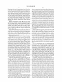
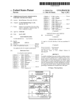
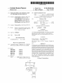
accordance with the present invention is particularly useful.
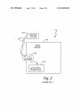
FIG. 2 is a block diagram of the ?eld device shown in FIG.
1.
30
transmitters, positioners, actuators, solenoids, indicator
lights, and others.
communication unit in accordance with embodiments of the
35
some installations, the process control loop is also used to
deliver a regulated current and/ or voltage to the ?eld device
for powering the ?eld device. The process control loop also
carries data, either in an analog or digital format.
Traditionally, analog ?eld devices have been connected to
the control room by two-wire process control current loops,
40
with each device connected to the control room by a single
two-wire control loop. Typically, a voltage differential is
present invention mounted to a ?eld device.
FIG. 5 is a front elevation view of a wireless power and
communication unit in accordance with another embodiment
of the present invention.
FIGS. 6 and 7 are diagrammatic views of a wireless power
and communication unit operating with a plurality of ?eld
devices in accordance with embodiments of the present
invention.
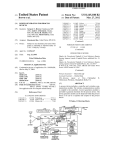
FIG. 8 is a block diagram of a wireless power and commu
maintained between the two wires within a range of voltages
from 12-45 volts for analog mode and 9-50 volts for digital
mode. Some analog ?eld devices transmit a signal to the
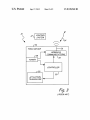
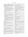
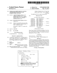
FIG. 3 is a block diagram of a ?eld device including wire
less communication circuitry for communicating with a
remote device such as a display or hand held unit.
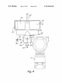
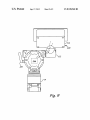
FIG. 4 is a front elevation view of a wireless power and
Typically, each ?eld device also includes communication
circuitry that is used for communicating with a process con
trol room, or other circuitry, over a process control loop. In
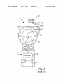
FIG. 1 is a diagrammatic view of an exemplary ?eld device
with which the wireless power and communication unit in
45
nication unit in accordance with embodiments of the present
invention.
FIG. 9 is a rear elevation view of a wireless power and
control room by modulating the current running through the
communication unit in accordance with an embodiment of
current loop to a current proportional to the sensed process
variable. Other analog ?eld devices can perform an action
under the control of the control room by controlling the mag
nitude of the current through the loop. In addition to, or in the
the present invention.
50
alternative, the process control loop can carry digital signals
The present invention includes a wireless power and com
used for communication with ?eld devices. Digital commu
nication allows a much larger degree of communication than
analog communication. Field devices that communicate digi
tally can respond to and communicate selectively with the
control room and/or other ?eld devices. Further, such devices
can provide additional signaling such as diagnostics and/or
alarms.
In some installations, wireless technologies have begun to
be used to communicate with ?eld devices. Wireless opera
tion simpli?es ?eld device wiring and setup. Wireless instal
lations are currently used in which the ?eld device is manu
DETAILED DESCRIPTION
55
60
munication unit for allowing ?eld devices that are designed
for wired communication to operate wirelessly. While some
devices are currently being developed which add wireless
communication to wired devices, such developments do not
function to untether legacy wired type ?eld devices from their
control loops since they still are wired to and receive power
from their control loops.
FIGS. 1 and 2 are diagrammatic and block diagram views
of an exemplary ?eld device with which a wireless power and
communication unit in accordance with the present invention
is particularly useful. Process control or monitoring system
factured to include an internal battery, potentially charged by
10 includes a control room or control system 12 that couples
a solar cell, or other technique to obtain power without any
sort of wired connection. Problems exist in using an internal
battery as the energy demands of wireless devices may vary
65 to one or more ?eld devices 14 over a two-wire process
control loop 16. Examples of process control loop 16 include
analog 4-20 mA communication, hybrid protocols which
US 8,538,560 B2
3
4
include both analog and digital communication such as the
Highway Addressable Remote Transducer (HART®) stan
ably, the protocol accommodates digital communication in
order to enhance the level of interaction between unit 1 00 and
device 14.
dard, as well as all-digital protocols such as the FOUNDA
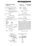
FIG. 4 also illustrates one or more photovoltaic cells 116
TIONTM Fieldbus standard. Generally process control loop
protocols can both power the ?eld device and allow commu
nication between the ?eld device and other devices.
mounted proximate a top surface 118 of housing 114. In one
In this example, ?eld device 14 includes circuitry 18
coupled to actuator/transducer 20 and to process control loop
16 via terminal board 21 in housing 23. Field device 14 is
sealed lid for the housing 114. In such embodiments, a clear
cover preferably extends over cell(s) 1 16 to protect them from
exposure. Cells 116 are preferably inclined at an angle of
embodiment, the photovoltaic cells(s) 116 form part of a
about 30 degrees and transform light falling thereon into
illustrated as a process variable (PV) generator in that it
electrical energy in order to power unit 100 and device 14.
couples to a process and senses an aspect, such as tempera
Since unit 100 is external to device 14, multiple variations of
unit 100 can be provided with varying photovoltaic cell con
ture, pressure, pH, ?ow, et cetera of the process and provides
and indication thereof. Other examples of ?eld devices
?gurations and/or sizes depending upon the speci?c power
include valves, actuators, controllers, and displays.
requirements of the ?eld device to which the unit will be
attached. Unit 100 also preferably includes wireless commu
Generally ?eld devices are characterized by their ability to
operate in the “?eld” which may expose them to environmen
tal stresses, such as temperature, humidity and pressure. In
addition to environmental stresses, ?eld devices must often
withstand exposure to corrosive, hazardous and/or even
nication circuitry (not shown in FIG. 4) which is coupled to
20
explosive atmospheres. Further, such devices must also oper
internal antenna proximate a radio-transparent portion of
ate in the presence of vibration and/or electromagnetic inter
ference. Field devices of the sort illustrated in FIG. 1 repre
sent a relatively large installed base of legacy devices, which
are designed to operate in an entirely wired manner.
FIG. 3 is a block diagram of a wireless ?eld device in
accordance with the prior art. Field device 34 includes inter
nal power supply module 38, controller 35, wireless commu
nication module 32, and actuator/transducer 20. Power sup
ply module 38 typically includes a battery that powers ?eld
device 34 for a period of time, until the battery needs to be
replaced. Some ?eld devices include a built-in solar cell. The
power from supply 38 energizes controller 35 to interact with
actuator/transducer 20 and wireless communications module
32. Wireless communications module 32, in turn, interacts
with other devices as indicated by reference numeral 24 via
antenna 26. One drawback with providing the wireless capa
bility of device 34 internally, is that if a battery, solar cell, or
wireless communications module should be damaged, the
entire ?eld device must be repaired or replaced. Another
disadvantage of using an internal battery is that some users of
25
power source is not scalable in the sense that varying energy
demands from various users cannot be accommodated well.
FIG. 4 is a front elevation view of a wireless power and
communication unit 100 attached to a ?eld device 14, shown
designed.
In accordance with one aspect of the invention, unit 100
30
includes a local user interface. Accordingly unit 100 may
include a display, such as an LCD display 122 that may be
mounted proximate one of cells 116. In order to receive local
user input, unit 100 can include one or more local inputs such
as button 124. A local user interface is important because
when the combined unit/?eld device system is operating
35
40
totally wirelessly, it is more convenient for a technician to
interact with the local user interface rather than wirelessly
trying to access the device via a handheld computing device
or the like. The local interface can be used to access the unit,
the ?eld device, or both. As de?ned herein “local user inter
face” means having either local user input(s) (such as a but
ton), local user output(s) (such as an LCD), or a combination
of the two. As illustrated in FIG. 4, the LCD can be co-located
with cell(s) 116.
FIG. 5 is a front elevation view of a wireless power and
45
communication unit in accordance with another embodiment
of the present invention. Wireless power and communication
unit 200 bears many similarities to wireless power and com
munication unit 100 and like components are numbered simi
larly. The primary difference between wireless power and
50
in phantom. Unit 100 preferably attaches to device 14 via a
standard ?eld device conduit 102. Examples of suitable con
duit connections include 1/2-14 NPT, M20xl.5, Gl/2, and
3/8-18 NPT. Unit 100 may include a joint allowing rotation
104 about axis 106 and rotation 108 about axis 110. Further,
attachment region 112 of unit 100 is preferably hollow in
order to allow conductors therein to couple unit 100 to device
14. In embodiments where positional adjustment of the hous
ing is not desired, attachment region 112 could simply be a
housing 114, or cell(s) 116 can be practiced as well. External
antenna embodiments, however, are particularly advanta
geous where unit 100 is ?eld hardened in order to withstand
environments similar to those for which ?eld devices are
wireless devices require much more energy than other users.
For example, if the ?eld device is activated once per minute,
versus once per hour, the energy consumption is greatly
increased. The energy usage also varies widely based on
whether the device is con?gured with minimum system ele
ments or is fully con?gured. Thus, the use of an internal
antenna 120. Providing external antenna 120 facilitates wire
less communication in comparison to internal antennas since
many ?eld-hardened enclosures are metal and would likely
attenuate the wireless signal. However, embodiments with an
55
communication unit 200 and wireless power and communi
cation unit 100 is the con?guration of the local user interface
display. Speci?cally, unit 200 does not include a display
proximate or co-located within the photovoltaic cell(s) 116.
Instead, display 202 is integrated into attachment region 112.
Preferably, display 202 is independently rotatable about axis
106 by approximately 270°.
Providing a user interface display proximate attachment
region 112 increases the modularity of unit 200. Speci?cally,
60
piece of conduit.
Unit 100 includes housing 114 that is mounted upon
housings 114 and all components therein can be manufac
tured similarly to achieve economies of scale. In installations
where a local user display is desirable, it can simply be added
as a module between housing 114 and joint 204 of attachment
attachment region 112. Housing 114 contains circuitry (de
region 112. Such modularity is also useful in embodiments
scribed with respect to FIG. 8) to allow unit 100 to power and
communicate with device 14 in accordance with a standard
where one unit 200 is used to operate and communicate with
multiple ?eld devices as will be described in greater detail
with respect to FIGS. 6 and 7. Thus, as installation site needs
industry protocol such as 4-20 mA, HART®, FOUNDA
TIONTM Fieldbus, Pro?bus-PA, Modbus, or CAN. Prefer
65
dictate, the power system, which includes the solar cell and
US 8,538,560 B2
5
6
antenna can be remotely mounted by utilizing an adapter
Sleep mode is any operating mode where power consumption
is reduced. With respect to ?eld devices, sleep mode could
?tted with a cable gland that connects to the top 206 of LCD
display 202. An adapter base is then used for mounting the
housing 114 and bringing the interconnecting cable via a
cable gland. This allows positioning housing 114 in an opti
result from commanding the ?eld device to set its operating
mal performance location while keeping a local user interface
ration of an activity period, an input from one or more of the
current at its lowest allowable current rail. Events which may
precipitate entering low-power mode could include: the expi
proximate each ?eld device.
local user inputs, communication from one or more attached
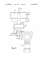
FIG. 6 is a diagrammatic view of a wireless power and
communication unit 300 in accordance with an embodiment
?eld devices, or wireless communication. Such events could
also be used to cause unit 360 and/or any attached ?eld
of the present invention. Wireless power and communication
devices to awaken from sleep mode. Additionally, controller
unit 300 is adapted for mounting remote from one or more
362 can selectively cause any attached ?eld device to enter
?eld devices 14. Unit 300 includes suitable power generation
and storage capabilities to power ?eld devices 14 simulta
sleep mode based upon any logic or rules contained in pro
gramming instructions within controller 362 and/or wireless
communication received via wireless communication mod
neously, sequentially, or asynchronously. As illustrated in
FIG. 6, each ?eld device 14 is coupled individually to unit 300
by an attachment region 112 illustrated diagrammatically in
ule 366. Preferably, local inputs, such as button 124 are user
con?gurable. Thus a single button could be used to awaken a
?eld device for a user-selectable period of time, and if so
FIG. 6. As stated above with respect to FIG. 5, attachment
region 112 preferably includes a local user interface, such as
button 124 and/or display 202. Since each ?eld device 14 is
individually coupled to unit 300, analog or digital communi
cation with individual ?eld devices 14 can be effected. While
it is preferred that user interfaces are included in attachment
regions 112 in the embodiment illustrated in FIG. 6, some
embodiments may provide an additional, or alternative user
interface embodied within unit 300.
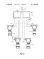
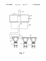
FIG. 7 is a diagrammatic view of unit 350 in accordance
20
25
with another embodiment of the present invention. Unit 350 is
illustrated with a single connection 352 to a plurality of ?eld
devices 14. Those skilled in the art will appreciate that the
con?guration illustrated in FIG. 7 has the ability to drastically
reduce interconnection wiring and efforts for coupling ?eld
30
con?gured, depressed again to cause the ?eld device to return
to sleep mode. In one embodiment, the con?gurable local
input button uses a jumper or switch to preset the following
functions:
Button Depress Time to Activateiselect either 1, 1.5, 2 or
3 seconds. Field device ignores button presses having
durations shorter than the preset.
Unit On Timeiselect either 10, 15, 30 seconds, or 5, 15,
30, 60 minutes.
If the button is pressed twice in close succession, the ?eld
device stays on for a preset period (for example 60
minutes) after which it returns to sleep mode.
If the button is pressed a second time after a preset interval
(for example 5 seconds) the ?eld device will return to
sleep mode.
devices 14 to unit 350. In order to be able to communicate
with individual ?eld devices 14, unit 350 preferably employs
digital communication utiliZing either a hybrid-type protocol
35
Controller 362 can also preferably cause portions of cir
cuitry within unit 360 or attached ?eld devices to enter sleep
mode. For example, wireless communication module 366
may be a commercially available General Packet Radio Ser
vice (GPRS) cell phone module, that has both a normal oper
40
user interface comprising a local user input and/or a local user
could cause module 366 to enter sleep mode when signi?cant
wireless communication is not warranted.
Energy converter 365 can be any device that is able to
output such as an LCD display.
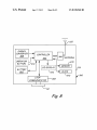
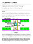
FIG. 8 is a block diagram of a wireless power and commu
convert potential energy in the environment proximate unit
360 into electrical energy. In the preferred embodiments,
or an all-digital industry standard protocol. Further, such a
protocol is used to power all of ?eld devices 14, simulta
neously, sequentially, or asynchronously as desired. FIG. 7
also illustrates each of ?eld devices 14 coupling to the net
work utiliZing an attachment region 112 illustrated diagram
matically. Thus, each of ?eld devices 14 may still have a local
nication unit in accordance with embodiments of the present
invention. Unit 360 includes controller 362, power storage
device 364 (illustrated as a battery), energy converter 365,
ating mode and a sleep mode. A signal from controller 362
45
loop communicator 368, and wireless communication inter
face module 366.
Controller 362 preferably includes a low-power micropro
cessor and appropriate charging circuitry to convey suitable
amounts of energy from cell(s) 116 and/or storage device 364
to power unit 360 and any ?eld devices coupled to attachment
region 112. Additionally, controller 362 also directs excess
energy from cell(s) 116 to storage device 364. Controller 362
can also be coupled to optional temperature measurement
circuitry such that controller 362 can reduce charging current
to storage device 364 if device 364 begins to overheat. For
50
converter 365 can employ therrnopile devices to generate
electricity from disparate temperatures using the Peltier
Effect. Further still, the process may provide a source of
energy in the form of compressed gas or the like, that could be
55
transformed into electricity. Finally, in embodiments where
the power storage device has a relatively large capacity in
60
365 may be omitted.
Wireless communication module 366 is coupled to con
troller 362 and interacts with external wireless devices via
antenna 120 based upon commands and/or data from control
comparison to the energy needs of the application, converter
example, the temperature measuring circuit may contain a
suitable temperature-sensing element, such as a thermo
couple coupled to storage device 364. An analog-to-digital
converter 365 is simply one or more photo-voltaic cells 116.
However, converter 365 can be any device, known or later
developed, that can translate potential energy near unit 360
into electricity. Thus converter 365 can include a generator
coupled to a movable member such that environmental
motion, such as waves or wind generate electricity. Further,
converter could convert the signal from the thermocouple to a
ler 362. Depending upon the application, wireless communi
digital representation thereof, and provide the digital signal to
cation module 366 may be adapted to communicate in accor
controller 362.
dance with any suitable wireless communication protocol
including, but not limited to: wireless networking technolo
gies (such as IEEE 802.11b wireless access points and wire
Controller 362 can be con?gured, through hardware, soft
ware, or both to actively manage power for itself and attached
?eld devices. In this regard, controller 362 can cause itself or
any desired ?eld devices to enter a low-power sleep mode.
65
less networking devices built by Linksys of Irvine, Calif.),
cellular or digital networking technologies (such as
US 8,538,560 B2
7
8
Microburst® by Aeris Communications Inc. of San Jose,
order to communicate in accordance with an industry proto
col, such as those set forth above. In embodiments where unit
360 is coupled to a plurality of ?eld devices that communicate
in accordance with different protocols, it is conceivable that
Calif), ultra wide band, free space optics, Global System for
Mobile Communications (GSM), General Packet Radio Ser
vice (GPRS), Code Division Multiple Access (CDMA),
spread spectrum technology, infrared communications tech
niques, SMS (Short Messaging Service/text messaging), or
multiple loop communicators could be used to allow control
ler 362 to interact with the various ?eld devices. The physical
any other suitable wireless technology. Further, known data
collision technology can be employed such that multiple units
connection(s) made through attachment region 112 allows
unit 360 to power and communicate with the ?eld devices. In
some embodiments, this can be done by providing power over
can coexist within wireless operating rage of one another.
Such collision prevention can include using a number of
the same conductors used for communication, such as a two
different radio-frequency channels and/or spread spectrum
wire loop. However, it is also contemplated that embodiments
techniques.
of the invention can be practiced where power is provided to
the ?eld device on separate conductors than those used for
communication. For ease of technician access, unit 360 may
include two or more terminals proximate loop communicator
368 or attachment region 112 in order to facilitate the cou
pling of a handheld con?guration device, such as the Model
375 Handheld device available from Rosemount, Inc. of Eden
Wireless communication module 366 can also include
transducers for a plurality of wireless communication meth
ods. For example, primary wireless communication could be
performed using relatively long distance communication
methods, such as GSM or GPRS, while a secondary, or addi
tional communication method could be provided for techni
cians, or operators near the unit, using for example, IEEE
802.1 lb or Bluetooth.
20
and LCD display block 376 in phantom being coupled to
cuitry that can interact with the Global Positioning System
(GPS). GPS can be advantageously employed in unit 360 for
controller 362. This illustration is intended to show that all
local inputs, be they on individual ?eld devices, wireless
mobile devices to allow ?nding the individual unit 360 in a
remote location. However, location sensing based upon other
25
techniques can be used as well.
Memory 370 is illustrated in FIG. 8 as being separate from
controller 362, but may, in fact, be part of controller 362.
Memory 370 can be any suitable type of memory including
volatile memory (such as Random Access Memory), non
volatile memory (such as ?ash memory, EEPROM memory,
Prairie, Minn.
FIG. 8 also illustrates optional operator button block 374
Some wireless communications modules may include cir
30
power and communication unit 360, or both are coupled to
controller 362. Additionally, local user displays, on each ?eld
device, wireless power and communication unit 360, or both
are also coupled to controller 362. This allows controller 362
to interact with each local display individually based upon
inputs from the ?eld device, the con?gurable button associ
ated with the ?eld device, one or more buttons or inputs
etc.) and any combination thereof. Memory 370 may contain
disposed proximate unit 360, or from wireless communica
program instructions for controller 362 as well as any suitable
tion.
administrative overhead data for unit 360. Memory 370 may
contain a unique identi?er for unit 360, such that unit 360 can
distinguish wireless communications meant for it among
other wireless communications. Examples of such an identi
?er could include, a MediaAccess Controller (MAC) address,
FIG. 9 is a rear elevation view of a wireless power and
35
the present invention. Wireless unit 400 is coupled to ?eld
device 14 as in previous embodiments. However, wireless
communication module 366 and/or antenna 120 can be
Electronic Serial Number, global phone number, Internet
Protocol (IP), or any other suitable identi?er. Moreover,
memory 370 may include information about attached ?eld
communication unit in accordance with an embodiment of
40
located within ?eld device 14 instead of within housing 114
of unit 400. Wireless communication module 366 and/or
antenna 120 can be added to ?eld device 14 as a feature board.
devices, such as their unique identi?ers, con?gurations, and
Further, wireless communication module 366 could be an
abilities. Finally, controller 362, using memory 370 can cause
the output of unit 360 to be provided in any suitable form. For
module 366 may be coupled to a controller within unit 400 via
example, con?guration and interaction with unit 360 and/or
integral part of ?eld device 14. Thus, in some embodiments,
one or more associated ?eld devices could be provided as
attachment region 112. In other embodiments, module 366
may be integral with the ?eld device, and in such embodi
HyperText Markup Language (HTML) web pages.
ments, unit 400 could simply provide operating power.
Clock 372 is illustrated as being coupled to controller 362,
but may also be part of controller 362. Clock 372 allows
accordance with embodiments of the present invention can
controller 362 to provide enhanced operation. For example,
45
In operation, wireless power and communication units in
50
add signi?cant capabilities to process monitoring and control.
clock 372 can be used to time the periods set forth above with
While the wireless output of the wireless power and commu
respect to con?gurable button 125. Additionally, controller
nication units may be simply indications of process variable,
they may also contain much more information. For example,
the wireless output could also include diagnostic and/or
maintenance information. Further, the wireless power and
362 can store information from one or more attached ?eld
devices, and correlate the information with time in order to
recognize trends. Further still, controller 362 can supplement
55
information received from one or more ?eld devices with time
communication unit could also provide alarms wirelessly if
information before transmitting it via wireless communica
one or more of the ?eld devices, or even the unit itself,
tion module 366. Further still, clock 372 can be used to
generates a fault. The unit may direct the wireless alarm to the
same entity as it normally sends wireless information to (such
as a control room), or it may send to an alternate entity, such
as a technician’s pager. Further, in embodiments where the
unit is coupled to more than one ?eld device, the wireless
output may be indicative of a combination of process vari
automatically generate periodic sleep/awaken commands for
unit 360 and/or ?eld devices.Another form of periodic use for
clock 372 is to cause controller 362 to issue, via module 366,
a heartbeat type signal to periodically indicate an acceptable
status to an external wireless device.
Loop communicator 368 is coupled to controller 362 and
60
able, or a higher level output. Further still, in embodiments
interfaces controller 362 to one or more ?eld devices coupled 65 where the multiple ?eld devices include PV generators, and
to one or more attachment regions 112. Loop communicator
one or more actuators that can effect a change in the process
368 is known circuitry that generates appropriate signals in
variable, the units themselves may actually provide local
US 8,538,560 B2
10
closed-loop process control autonomously without control
9. The system of claim 1, wherein the conduit has a size
selected from the group consisting of a 3/8-18 NPT, a 1/2-14
NPT, a M20xl.5, and a Gl/2.
room interaction, but still subject to wireless communication.
Although the present invention has been described with
reference to preferred embodiments, workers skilled in the art
will recognize that changes may be made in form and detail
without departing from the spirit and scope of the invention.
What is claimed is:
1. A process communication system comprising:
a process variable generator coupleable to the process, the
process variable generator being operably coupled to a
10. The system of claim 1, wherein the attachment region
includes at least one degree of freedom.
11. The system of claim 1, wherein the attachment region
allows the housing to be rotatable about a ?rst axis.
12. The system of claim 11, wherein the attachment region
allows the housing to the rotatable about a second axis that is
substantially orthogonal to the ?rst axis.
13. The system claim 1, and further comprising a photo
transducer and having communication circuitry for
communication over a process control loop and receiv
voltaic cell disposed near a top surface of the housing at an
ing electrical power from the process control loop to
power the process variable generator;
angle of approximately 30 degrees with respect a bottom
surface of the housing.
a wireless power and communication unit for providing
wireless operation to the process variable generator, the
14. The system of claim 1, wherein the local user interface
includes a button.
unit including:
15. The system of claim 14, wherein the button is user
a housing;
con?gurable.
an attachment region coupling the housing to the process
variable generator through a standard ?eld device con
20
a power storage device disposed within the housing and
con?gured to power the process variable generator;
17. The system of claim 1, wherein the user interface
includes a display.
18. The system of claim 17, wherein the display is an LCD
a loop communicator connected to the process variable
generator via the attachment region and con?gured to
25
interact with the process variable generator via the com
munication circuitry;
a controller coupled to the power storage device and loop
communicator, the controller being con?gured to inter
act with the process variable generator using the loop
communicator and con?gured to actively manage power
30
a wireless communication module coupled to the control
35
based upon interaction with the process variable genera
tor; and
wherein the power management includes causing at least a
portion of the wireless power and communication unit to
enter a sleep mode.
2. The system of claim 1, wherein the power storage device
is a battery.
3. The system of claim 1, and further comprising a energy
converter coupled to the controller and being adapted to con
40
45
8. The system of claim 7, wherein the temperature sensor is
operably coupled to the controller through an analog-to-digi
tal converter.
25. The system of claim 24, wherein the loop communica
tor is adapted to communicate digitally with both process
variable generators.
26. The system of claim 1, wherein the controller includes
a microprocessor.
27. The system of claim 1, wherein the loop communicator
milliamps.
28. The system of claim 1, wherein the loop communicator
provides a two-wire connection to the process variable gen
erator, which two wire connection provides power and com
55
7. The system of claim 3, and further comprising a tem
perature sensor operably coupled to the controller and dis
posed to sense a temperature of the energy storage device, and
device based at least in part upon a signal from the tempera
communication unit to an additional process variable genera
tor and power and communicate with both process variable
is con?gured to sense a current ranging between 4 and 20
50
energy converter.
ture sensor.
hardened.
24. The system of claim 1, and further comprising an
generators.
ity.
wherein the controller selectively charges the energy storage
22. The system of claim 21, wherein the display is rotatable
about the attachment region.
23. The system of claim 1, wherein the housing is ?eld
region being con?gured to couple the wireless power and
vert a source of environmental potential energy into electric
4. The system of claim 3, wherein the energy converter
includes at least one photo-voltaic cell.
5. The system of claim 4, wherein the at least one photo
voltaic cell seals a portion of the housing.
6. The system of claim 3, wherein the controller is adapted
to recharge the power storage device with electricity from the
19. The system of claim 17, wherein the display is located
proximate a top surface of the housing.
20. The system of claim 19, wherein the display is located
proximate a photo-voltaic cell.
21. The system of claim 17, wherein the display is mounted
additional attachment region, the additional attachment
a local user interface;
wherein the power management includes causing the process
variable generator to enter a sleep mode; and
display.
proximate the attachment region.
for the wireless power and communication unit and the
process variable generator;
ler and being con?gured for wireless communication
16. The system of claim 14, wherein the button is disposed
proximate the attachment region.
duit;
munication with the process variable generator.
29. The system of claim 1, wherein the power management
includes causing the process variable generator to enter a
sleep mode.
60
30. The system claim 1, wherein the controller causes the
portion of the wireless power and communication unit to
enter a sleep mode based upon user input.
31. The system of claim 1, wherein the power storage
device is selected based upon a scale of power required by the
process variable generator.
*
*
*
*
*
UNITED STATES PATENT AND TRADEMARK OFFICE
CERTIFICATE OF CORRECTION
PATENT N0.
: 8,538,560 B2
APPLICATION NO.
: 10/850828
DATED
INVENTOR(S)
: September 17, 2013
: Gregory Brown et a1.
Page 1 of 1
It is certified that error appears in the above-identi?ed patent and that said Letters Patent is hereby corrected as shown below:
On the Title Page, Item (63)
Related US. Application Data
?led on April 29, 2005 should be --filed on April 29, 2004--.
Signed and Sealed this
Tenth Day of December, 2013
Margaret A. Focarino
Commissionerfar Patents 0fthe United States Patent and Trademark O?ice