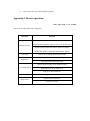
1
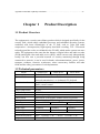
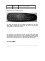
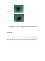
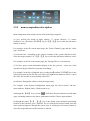
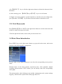
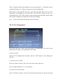
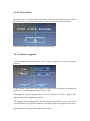
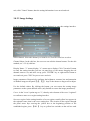
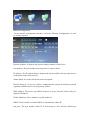
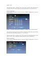
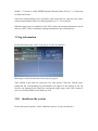
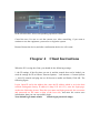
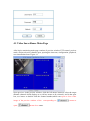
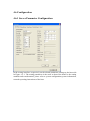
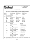
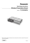
DVR User’s Manual Welcome Thank you for purchasing our DVR! This manual is designed to be a reference tool for the installation and operation of your system. Here you can find information about this series DVR features and functions, as well as a detailed menu tree. Before installation and operation please read the following safeguards and warnings carefully! Important Safeguards and Warnings Do not place heavy objects on the DVR. Do not let any solid or liquid fall into or infiltrate the DVR. Please brush printed circuit boards, connectors, fans, machine box and so on regularly. Before the dust cleaning please switch off the power supply and unplug it. Do not disassemble or repair the DVR by yourself. Do not replace the components by yourself. Environment Please place and use the DVR between 0℃ and 40℃.Avoid direct sunlight. Stay away from heat source. Do not install the DVR in damp environment. Do not use the DVR in smoky or dusty environment. Avoid collision or strong fall. Please insure the DVR level installation in a stable workplace. Please install in ventilated place. Keep the vent clean. Use within the rating input and output scope. Contents Chapter 1 Product Description ..................................................................................................... 3 1.1 Product Overview ............................................................................................................... 3 1.2 Technical parameters ........................................................................................................... 3 chapter 2 Introduction to Front Panel................................................................................................ 4 2.1 Panel Description ................................................................................................................ 4 2.2 Product Interface Description ............................................................................................. 5 2.3 Remote Control Description ............................................................................................... 7 2.4 Video format ....................................................................................................................... 7 Chapter 3 operating system instructions ........................................................................................... 8 3.1 on / off ................................................................................................................................. 8 3.2 preview ................................................................................................................................ 8 3.3 Basic operating instructions menu ...................................................................................... 8 3.3.0 boot menu ................................................................................................................ 8 3.3.1 enter the menu mode ............................................................................................... 9 3.3.2 menu composition description ............................................................................. 9 3.3.3 Exit Menu mode .................................................................................................... 10 3.4 Main Menu Introduction ................................................................................................... 14 3.5 Video playback .................................................................................................................. 15 3.5.1 File Search............................................................................................................. 15 3.5.2 Search Results ....................................................................................................... 16 3.5.3 Playback Tool Control ........................................................................................... 17 3.6 Manual recording .............................................................................................................. 13 3.7 PTZ Control ...................................................................................................................... 14 3.8 Menu ................................................................................................................................. 14 3.8.1 Management Tools ................................................................................................ 15 3.8.2 System Settings ..................................................................................................... 18 3.9 log information .................................................................................................................. 28 3.10 shutdown the system .................................................................................................... 28 Chapter 4 Client Instructions ................................................................................................... 29 4.1 Video Surveillance Main Page .......................................................................................... 29 4.2 bit stream selection............................................................................................................ 30 4.3 PTZ Control ...................................................................................................................... 30 4.4 Advanced Settings box ...................................................................................................... 30 4.5 Intercom Control ............................................................................................................... 31 4.6 Configuration .................................................................................................................... 31 4.6.1 Server Parameter Configuration ............................................................................ 31 4.6.2 Channel Parameters Configuration ....................................................................... 31 4.6.3 Alarm Configuration Parameters ........................................................................... 32 Chapter 5 Mobile Monitor .............................................................................................................. 32 Chapter6 FAQ and maintenance…………………………………………………………………..32 Chapter7 Maintenance…………………………………………………………………………….36 Appendix 1.Mouse operation……………………………………………………………………..37 Appendix 2 Hard disk capability calculation…………………………………………………….37 Chapter 1 Product Description 1.1 Product Overview The equipment is a security surveillance product which is designed specifically for the security field, which adopts embedded processor and embedded operating systems, combined with latest technologies in the IT field, such as video and audio compression / decompression, high-capacity hard disk recording, TCP / IP network technology,and the codes are solidated in the FLASH, which makes system run more stable. The equipment at the same has the fearture of digital video and audio recorder (DVR) and digital video and audio server (DVS), which can not only independently locally, but also orm a powerful network of security monitoring through being connected to network. it can be used in banks, telecommunications, power, justice, transport, residence, factories, warehouses, water conservancy facilities and other fields and the safety precautions of each departments. 1.2 Technical parameters Model Operating System System resources operation interface Video Standard Video compression Audio Compression Video modes Video search Backup Video input Video output Audio input Audio output Monitoring Resolution Playback Resolution Image control 9XX4-DVR 9XX8-DVR 9X16-DVR Embedded Linux Operating System At the same time 4/8/16 channel CIF real-time video and network transmission, 1 or 4-channel CIF playback graphical operation interface,which supports mouse, panel, remote control PAL、NTSC H.264 ADPCM Manually, timing, alarm, motion detection timesearch, event search, channel search, log search Network backup, USB backup 4 channel BNC 8 channel BNC 16 channel BNC 1 channel BNC,1 channel VGA output (optional) 2 channel 2 channel 2 channel 1 channel 1 channel 1 channel PAL:720x576(D1);NTSC:720x480(D1) PAL:352x288(CIF);NTSC:352x240(CIF) 6 level adjustable Motion detection Screen display Video rate Video save Local playback Alarm input Alarm output PTZ control HDD interface Network interface USB interface Power the detection area of each channel (16 × 16), which can be set multi-level sensitivity 1,4 screen 1、4、8 screen 1、4、9、16screen PAL:25 frames/sec NTSC:30 frames/sec hard disk, network 1 or 4 channel playback at CIF resolution No have No have 4 channel No have No have 1 channel RS485 1 SATA interface 2 SATA interface RJ45 10M/100M self-adaptive Ethernet port 1 USB2.0 high-speed interface; 1 USB1.1 interface 12V 3A Chapter 2 Intruction to Front Panel 2.1 Panel Description 2.1.1 9XX4-DVR Front Panel IR:IR Sensor :Direction Key QUAD:Multi-screen Preview CH4:Channel 4 CH3:Channel 3 CH2:Channel 2 CH1:Channel 1 RUN:Run indicator PWR:Power indicator Enter:Enter PAUSE:Pause PTZ:PTZ Control FN:Input Shift REC:Manual Recording PLAY:Video Playback Esc:Escape Menu:Menu 2.1.2 9XX8-DVR Front Panel IR:IR Sensor :Direction Key HDD:HDD indicator PWER:Power indicator Multi:Multi-screen preview REC:Recording Esc:Escape Menu:Menu FWD:Fast Forward PLAY:Play/Pause REW:Fast Backward Ok/PTZ:OK/PTZ REC:Recording indicator CH8:Channel 8 CH7:Channel 7 CH6:Channel 6 CH5:Channel 5 CH4:Channel 4 CH3:Channel 3 CH2:Channel 2 CH1:Channel 1 Power:Power key 2.1.3 9X16-DVR Front Panel IR:IR Sensor :Direction Key HDD:HDD indicator Power:Power indicator Esc:Escape PAUSE:Pause Next:Next video Last:Last video FWD:Fast Forward PLAY:Play video REW:Fast Backward OK:OK REC:Recording indicator PTZ:PTZ Control REC:Recording Mute:Mute Search:Video Search Menu:Menu Multi:Multi-screen preview Ch+:Channel Plus Ch-:Channel Minus 2.2 Product Interface Description 2.2.1 9XX4-DVR Interface Letter Name Description POWER Power VGA VGA interface Connect VGA device,like computer NET Internet interface To connect LAN,WAN.RJ45 Interface VOUT Video out BNC Connector VIDEO-IN Video in Connect channel Connector Fan Temperature control Fan Temperature control fan(work temperature higher than 40℃) DC-12V Power connector To connect DC12V3.5A R485 RS-485 To connect PTZ USB USB2.0 To connect USB device like USB flash memory USB USB1.1 To connect mouse AUDIO-OUT Audio out Audio out,BNC Connector AUDIO-IN Audio in Audio in,RCA Connector 2.2.2 9XX8-DVR Interface 1-4 camera in,BNC when Letter Name Description DC12V Power RS485 RS-485 To connect PTZ VGA VGA Connect VGA device,like computer USB USB2.0 To connect USB device like USB flash memory USB USB1.1 To connect mouse VIDEO-IN Video in To connect cameras,BNC Connector LAN Internet interface To connect LAN,WAN.RJ45 Interface AUDIO-IN Audio in Audio in,RCA Connector AUDIO-OUT Audio out Audio out,BNC Connector VIDEO-OUT Video out BNC Connector Fan Temperature control Fan Temperature control fan(work when temperature higher than 40℃) ALARM Alarm interface Alarm in/out(optional) 2.2.3 9X16-DVR Interface Letter Name Description DC12V Power RS485 RS-485 To connect PTZ USB USB2.0 To connect USB device like USB flash memory USB USB1.1 To connect mouse LAN Internet interface To connect LAN,WAN.RJ45 Interface VGA VGA Connect VGA device,like computer AUDIO-IN Audio in Audio in,RCA Connector AUDIO-OUT Audio out Audio out,BNC Connector VIDEO-IN VIDEO-IN To connect cameras VIDEO-OUT Video out Video out,BNC Connector Fan Temperature control Fan Temperature control fan(work temperature higher than 40℃) ALARM Alarm interface Alarm in/out (optional) when 2.3 Remote Control Description Remote control mode is the same as the panel. DEV button: after pressing DEV key, according to the number keys enter device number which is agreement with the host, press "OK" button to save the settings. Then operation of the device takes into force. SHIFT: the current version does not support the key. CLEAR: when setting covering and mootion detection region, clear the current constituency. Note: when there are more than one device in the same place, remote control firstly must according to device number select a piece of equipment, so defining a unique device number for each device is a must, or remote control operation may at the same time make effect to more than one device , which has the same device number. 2.4 Video format In the video format switches on the device motherboard, perform video format settings. PAL format Status: NTSC format Status Chapter 3 operating system instructions 3.1 on / off Confirm that swith-in current and voltage is consistent with the hard disk recorder which meets requirements, and ensure that middle power outlet of the hard disk recorder is well grounded. After access to power, the device starts 【POWER】 light which is green,and after entering the system, the panel RUN light normally flashes. 3.2 preview After normal equipment boot,immediately enter the preview screen. In the preview screen you can see date, time, channel name of the system.Press number key corresponding to panel or click the left mouse button, you can preview a single image; then press Panel "Quard" button or click the left mouse button, you can return to a multi-screen preview status. 3.3 Basic operating instructions menu 3.3.0 boot menu Input user name and input user password to login. Default user name :admin default user password: 空 empty 3.3.1 enter the menu mode 【Main Menu / MENU】 key to enter the device's main menu interface. 【PLAY / PLAY】 shortcut keys, enter playback interface. 【Video / REC】 shortcut keys, enter manually recording interface. 【PTZ】 shortcut keys,enter PTZ control interface. 3.3.2 menu composition description Menu component units mainly consist of the following categories: (1) box: provide two kinds of status options, "√" means effective, "□" means ineffective, use 【confirm / ENTER】 key or 【↑】, 【↓】 key or click the left mouse button to choose. For example: in the file search menu page, the "Select Channel" page and the "video type" check box. (2) selection box: According to the options contents of the system drop-down box, select the target content. Use 【↑】, 【↓】 key or click the left mouse button to select. For example: in the file search menu page, the "Storage Device" selection box. (3) list box: query results information display in the list, you can select one of the operation in the provided list to operate accordingly. For example: in the list of playback query results,press【confirm / ENTER】key or the left mouse button to play the file; you can use the right mouse button to select / cancel the video file in order to easily backup video files. (4) edit box: through the edit box, enter the target name. For example: in the System Configuration menu page, the "device name" edit box, enter numbers, English letters, Chinese and so on. a) through the 【OK】 key or in the " ", click the left mouse button to switch input types, including numbers,case letters, punctuation marks, Chinese input method. b) through the panel 【←】, 【→】 key or the mouse cursor mobilely positioning location of the edit box, press "ENTER" key or click the left mouse button, then the enter keyboard appears, through the arrow keys or clicking the left mouse button to select the target characters which need to be entered . c) by【SHIFGT 】 key or click the right mouse button to delete the character before the cursor. d) After entering, press 【MENU】key or【ESC】 key to exit edit status. (5) button: it's used to perform a specific function or enter the next one setting menu, press【confirm / ENTER】 key and the left mouse button to determine access. 3.3.3 Exit Menu mode Press 【MENU】, 【Exit / ESC】 or the right mouse button to exit the menu mode and switch to a multi-screen preview mode. Click the right mouse button, return to the previous menu level. 3.4 Main Menu Introduction Press MENU key or the right mouse button to pop-up the main menu, main menu consists of the following three components: Preview mode: in the menu column,you can select the corresponding screen preview mode. Shortcut menu: in the menu column, respectively have: video playback, manual recording, shortcut menu of PTZ control, you can directly emter the corresponding menu pages. The main menu bar: after clicking to enter,include: management tools, system settings, log query, shut down the system of the menu page and so on . 3.5 Video playback Click "video playback" of the main menu column, enter file search interface. 3.5.1 File Search Select channel: Select the target channel you want to search, click the check box to choose. Video Type: Select the video type which needs to search. "√"means to be checked; "□" means not to be selected. Time setting: in the edit box enter the beginning and end time to search the video. Storage device: in the selection box select the target backup storage device. Search files button: after setting the search criteria, click the button, then the system begins to search the corresponding video files, and enter the search results interface. NOTE: If video files meeting the search criteria are more than 4000, then the system only shows the latest 4000 video files. If you want to find the updated files, please modify the search criteria. Playback By time: According to set starting and ending time to start playback of video material. (No distinction of video types) playback tools control, please refer to 3.5.3 By time backup: Backup all video data to the designated storage devices during the set beginning and ending time. 3.5.2 Search Results After setting search criteria, click "File Search" button, then enter the search results interface. Playback video files: in the search results list box, through the upper and lower key or moving the mouse to position the target file, click the "ENTER" key or left mouse button to start playing the file. page curl:Display searched video file by page, you can click "Previous" "Next" button or in the page number box enter the target page and click the "Go" button to curl page,and you can also scroll the middle button of mouse to next page. Backup: In the search results list, through the upper and lower key moving the mouse to target file, and then use the OK key or the right mouse button to select the file, in the storage equipment selection box, select the target storage devices, and then click "Backup" button, then the selected video file will be backed up to the target storage device. Cancel button: return to the previous menu level. 3.5.3 Playback Tool Control When selecting the file playback or playback by time, it will enter the video playback interface. Playback toolbar: In the bottom of playback interface,playback toolbar will appear, and you can click the right mouse button to hide / show toolbar. When at the same time Multi-screen is being playback, after hiding tool bar, you may by clicking the left mouse button zoon in or out corresponding channel video., Stop Play: Click interface. button, the system will stop playing and exit the playback Pause / Play: Click playback. button to pause playback, click Single-frame playback:when it is pause mode, click playback, and each time click to forward play one. Slow play: Click Quick play: Click settings. to to continue to video it will be single-frame slow play, click again to set the slow-play multiples. to slow play, click again to carry out quick-play multiple Previous paragraph / next paragraph: Click or button, every time click once of a time or the next section, playback progress will forward or backward progress 10%. Close / Open Sound: click or can open or close the sound of playback files. Playback status information: on the right playback tool bar respectively show: playback speed, play progress, the played time, total time of video file. Exit Play: Click "ESC" key or button to exit playback screen at any time; after playing all,automatically quit the playback screen. 3.6 Manual recording Click the "manual recording" in the main menu column to enter its settings interface. 【Video / REC】 key or in the main menu column, use mouse to click "Manual recording" to directly enter manually setting recording interface. Manual Video Interface Description Manual recording interface consists of the following components: Channel number: it corresponds to the video channel of the device. Channel status: it indicates video status of the corresponding channel, and status lights are green ,and " " indicates that no open video; red " "means to open the video. Video status: when the state lights are surrounded by a coil of " ",and" " means the corresponding channel open the network video transmission. When the system is in recording state (regardless of video type), in the lower left corner of the channel preview screen will show " " which means the system is recording. Full enable / disable the button: Click the button to stop or open the video settings of all channels. Back button: Click the back button, then exit manual recording interface, return to the main menu bar. Note: Manually start the video, only through the manually stopping, otherwise the video would continue. 3.7 PTZ Control Click "PTZ control" of in the the main menu column to enter setting interface. The main operations of PTZ control are: directional control; horizontal sweep; zoom control; adjust the focal length; adjust aperture; PTZ speed. After switching page, you can call the preset points; start / stop automatic cruise; wiper control; lighting control; auxiliary equipment control. Description: The called preset points must be set up, and for the cruising path setying method see 3.8.2.8 PTZ settings,in which when the set cruise path number is less than 2 digits, you need to add 0 to make up enough numbers before the value of the set corresponding cruise path number. 3.8 Menu Click "menu" in the main menu column to enter the main menu page, and one-level menu includs: management tools, system settings, log Query, shut down the system. 3.8.1 Management Tools It includs hard disk management, user management, restore to the default, clear the alarm, software upgrades, time settings, version information. 3.8.1.1 Hard disk management SATA: It displays hard disk information of the current system, "o" means the success of the hard disk test; "X" indicates means not to detect the hard disk. Hard Format: In the hard disk select box, select the target disk, and you can view the information corresponding to the hard disk, click "Format" button to turn up a confirmation page, click "OK" button to begin formatting the hard disk; after the hard disk format is completed, the hard disk can be used normally. Note: before the hard disk formatting, stop all recording. 3.8.1.2 User Management Create and add users, delete users and modify user information. (the users except Admin have no rights to set up additional user rights) Create a new user Enter the "User Management" interface, click the "Add" button to enter adding user interface. 1, enter the new user name In the User Name edit box, enter a new user name (such as the user). Note: for input methods, see 3.3.2 (4) edit box 2, set the new user's password In the "Add User" interface, select "Set Password" button,enter the password setting page, and directly enter the new password, which is less than six figures. 3, setting up new user's permissions In the "Add User" interface, set the new operating authority for the user , within the box of the corresponding function to choose,and "√" means that the user can use the permission, "□" means that the user can not use the permission. 4, save the new user's settings Click "Confirm" button to set the new user information to save, and "Cancel" means not to save. Modify user Enter the "User Management" interface, in the user list, click the right mouse button or panel "ENTER" key to select the target user, and then click "Modify" button, enter the "Modify User" page to modify user information. Notes: admin administrator can modify permissions of other users. Delete User Enter the "User Management" interface, in the user list, click the right mouse button or panel "ENTER" key to select the target user, click the "delete" button, and after confirmation delete the user. 3.8.1.3 Restore Default Restore the system configuration parameters as the factory configuration,and after restore, the system restarts automatically. 3.1.8.4 Clear Alarm Manually remove all of the alarm information. After the successful removal of alarm, the system will give prompt information of "has successfully cleared warning". After confirmation ,return to management tools the page. 3.8.1.5 Software upgrade In the management tools interface, select "software upgrade" to enter its operation interface. In the upgrade option box, select objectives which need to upgrade; in the upgrade option box, select the upgrade mode: FTP, or USB. USB Upgrade: copy the upgrade files to the root directory of U disk, and then click OK to upgrade the system. plug U disk, FTP Upgrade: put the upgrade file into the root directory of FTP server's, and set the server IP address as the specified address, and finally click OK to upgrade the system. After upgrade, the system will automatically restart. NOTE: Motherboard upgrade file name must be: mainboard.bin; Panel upgrade file name must be: panel. Bin When system is being upgraded, don't disconnect the power supply, so as to avoid equipment failure. 3.8.1.6 Time Settings Enter date and time page, in the "Date", "time" edit box respectively enter the exact date and time, confirm the save,and cancel to exit. 3.8.1.7 Version You can see the device name, model, related information of version number. 3.8.2 System Settings In the main menu page, select "System Settings" to enter its sub-menu interface. 3.8.2.1 System Configuration In the System Settings interface, select "System Configuration" to enter the setting interface. Device number: When using the remote control to remote and control operate equipment,which must be through the device number communicating with the remote control,the remote control must correspond to the device number to achieve remote operation.For the settings of remote control device number, see the 2.3 instructions. Equipment name: device name is generally defined as the regional name of control points, and when remote access, you can intuitively find the monitoring point what you want to access. The default device name is "NetDVR". For editing method, see 3.3.2 (4) edit box. Equipment expiration: When selecting "coverage",and when the hard disk inside the device are all fully recorded, the system covers the first video data, to achieve the purpose of circulating the video. Keyboard lock time: the system has no operatopm during the set keyboard lock time, then the system will automatically log off the current user, and it needs to re-sign-on system to operate. Switching time: switching time is cycle time period of single-channel display. preview Video format: The device supports PAL and NTSC video output formats. The default output format is "PAL". For setting method please refer to 2.4. VGA resolution: the user can adjust the VGA display resolution according to VGA monitors. Menu Transparency: After entering the user operation interface,you can by adjusting the level of menu transparency to achieve the transparency between the preview screen and menu. Language: According to the needs of users, you can set the menu language type, select Simplified Chinese, English. Status display: in the preview screen, set whether to display video mode, status, and open the information icon of motion detection, which is marked as "√" to show state; it's marked "□" as non-display status. Icon status description in the lower left corner of vhannel preview screen: " " Indicates that the system is recording video (regardless of video type). " " Indicates timing recording status. " " means the manual recording status. " " means Motion Detection Status " " means Motion Detection recording After the page setting is completed, click "OK" button, the settings are saved and exit; click "Cancel" button, the setting information is not saved and exit. 3.8.2.2 Video Settings In the System Settings interface, select "Video Settings" to enter the settings interface. Select channel: Select the target channel you want to set, click the select box to select. Stream: Select the code stream which needs to set, which are respectively "main stream" and "sub-stream." Stream type: Select the needed video stream type, and "video streaming" means only to encode the video when the system is recording video; "composite flow" means to encode audio and video at the same time when system is recording . Bit rate type: Users can set "fixed rate" and "variable bit-rate", and "fixed rate" means the system encodes images according to bit rate and video frame rate which the user sets; "variable bit-rate" means the system encodes images according to image quality and video frame rate which the user sets,but the bit rate is that the system automatically adjust according to the video scene. Bit rate: the bit rate which users select to encode according to need. The higher the bit rate, the better the image, but the occupied disk space is larger. Video frame rate: the video frame rate which users select to encode according to need. The higher the frame rate,the better the image smooth, but the occupied disk space is larger. Copy to: In the select box on the right of Copy To button, select the target channel, click the "copy to" button, and the system will apply the current channel setting information to other target video channel. When the page setup is completed, click "OK" button,then the settings are saved and exit; click "Cancel" button, then the setting information is not saved and exit. 3.8.2.3 Image Settings In the System Settings interface, select "Image Settings" to enter the settings interface. Select channel: Select the channel you want to set, click the select box to select. Channel Name: In the edit box, the user own can edit the channel names. For the edit method, see 3.3.2 (4) edit box. Display Name: "√" means display, "□" means not to display. Click "Location" button to enter the setting interface,you can via panel keys or the mouse dragging the red channel name to set, and after set-up, press "ENTER" key or right mouse button to save and exit, press "ESC" key not to save and exit. Image parameters: Respectively configure the brightness, contrast, hue and saturation of channel imag,use the panel【↑】, 【↓】 keys or the mouse to drag scroll to adjust. Use the default values: By clicking the button, you can restore the setting image parameters to the system default value (only limited to restore the image parameters). Cover: in the "cover" option tag set "√", thereby active button of the cover "regional" to confirm to enter cover region setting interface. Set cover region: In the setting interface of cover region,a small yellow box appears in the regional center, that is the cover setting box. The creation of the region: through the panel arrow keys moving the yellow box to the beginning position of the established region, press 【OK 】 key to (yellow box switches to the red box each other) turn it into a red box (red box is the cover region box which takes into force); and then press the arrow keys to adjust the size of the region, and the minimum can be set to a small square ,and the maxium can be set up to four cover areas. Click the left mouse button or long-press left button to move the mouse to select area,and after selection,you can press "ENTER" key or click the middle button of mouse to exit and save, "ESC" key not to save and exit. Partial elimination: mave the yellow box to the start region which need to be eliminated(upper left), press【OK 】 key to enter a small black box (to eliminate the regional boxes) and the localized area is eliminated. After elimination, press【confirm / ENTER】 key to save and exit, and if you press 【exit / ESC】 key, the elimination operation is invalid. In the red box, click the left mouse button or long-press left key to move mouse to eliminate area, click the middle button of mouse to exit and save. Clear All: Press 【MENU】 to clear all covered areas of the channel. Copy to: In select box on the right of the Copy To button, select the target channel, click the "Copy to" button, and the system will apply the current channel setting information to other target video channel. Note: Channel names can not be copied. After the page setup is completed, click "OK" button, the settings are saved and exit; click "Cancel" button, the information is not saved and exit. 3.8.2.4 Alarm Input In the System Settings interface, select "Alarm Input" to enter its settings interface. Input Channel: Select the channel you want to set, click select box to choose. Alarm type: you can set high, low voltage, please select the appropriate level for the alarm corresponding to alarm input channel connection. Detection: you can set whether to test alarm input signal. Select "Yes" then the following setting functions take into force; "No" means not to do any treatment. PTZ linkage: Click the "Settings" button to enter PTZ linkage settings interface. Select a channel number, and perform the relevant settings of PTZ linkage: preset point, cruise, trajectory.For PTZ setting methods, see 3.8.2.8 Delay: When alarm input ends, the setting needs the extension of time of various treatment. Buzzer: Whether to trigger the alarm buzzer. "√" means enable, "□" means invalid. Video Channel: When setting alarm input,you need to trigger the specified video channel number. Alarm Output:When setting alarm input,you need to trigger the specified alarm output channel number. Copy to: In the select box on the right of Copy To button, select the target channel, click the "Copy to" button, and the system will apply the current channel setting information to other target video channel. After the page setup is completed, click "OK" button,the setting information is saved and exit; click "Cancel" button, he setting information is not saved and exit. 3.8.2.5 Alarm Output In the System Settings interface, select "Alarm output" to enter its settings interface. Output Channel: Select the target channel you want to set, click select box to choose. Alarm type: "Normal close-type" and "always open-type"select corresponding type. Time period: "√" enable valid time settings of alarm output, and only during the effective setting period, alarm signal can be exported. After the page setup is completed, click "OK" button,the setting information is saved and exit; click "Cancel" button, he setting information is not saved and exit. 3.8.2.6 video deployment In the System Settings interface, select "Video deployment" to enter its settings interface. Select channel: Select the channel you want to set goals, click the select box to select. Weeks: Select which day you want to set, and you can set it separately; "All" means all dates. Video types and time periods: during the four time periods,you can set different video types during each period, timing video (red), motion detection recording (green), alarm recording (yellow). "√" means enable; "□" means invalid. There is time period status displaying below, and the overall schedule from 0 to 24 hours. Copy to: In the select box on the right of Copy To button, select the target channel, click the "Copy to" button, and the system will apply the current channel setting information to other target video channel. After the page setup is completed, click "OK" button,the setting information is saved and exit; click "Cancel" button, he setting information is not saved and exit. 3.8.2.7 Video Detection In the System Settings interface, select "Video Detection" to enter its settings interface. Select channel: Select the target channel you want to set, click the select box to select. Type:you can select motion detection, video loss. Video Channel: Select the specified alarm output channel number which needs to trigger after detection occurred. Alarm Output: Select the specified video channel number which needs to trigger after detection occurred. Buzzer: Whether to trigger the alarm buzzer. "√" means enable, "□" means invalid. Delay: When alarm input ends, the setting needs the extension of time of various treatment. Regiona: Set motion detection area, and the setting methods , see 3.8.2.3 setting cover region. Sensitivity: Select to trigger motion detection sensitivity. "No detection" means the above set parameters are invalid. Copy to: In the select box on the right of Copy To button, select the target channel, click the "Copy to" button, and the system will apply the current channel setting information to other target video channel. After the page setup is completed, click "OK" button,the setting information is saved and exit; click "Cancel" button, he setting information is not saved and exit. 3.8.2.8 PTZ Settings In the System Settings interface, select "PTZ Settings" to enter the settings interface. Select channel: Select the target channel you want to set, click the select box to select. Rate: Select the rate which matches the connected PTZ. Data Bits: Select the data bits which match the connected PTZ. Stop Bits: Select the stop bit which matches the connected PTZ Checksum: Select the check value which matches the connected PTZ. Flow Control: The selected item must be consistent with the matched PTZ flow control settings. Protocol Type: The selected item must be consistent with the matched PTZ protocol. Decoder Address: Enter the address of the specified decoder. Preset point setting: preset point is to preset and memory position, focal length, aperture and zoom of camera , while using a number to mark these settings. Add a preset point: In the pre-edit box enter a preset point,the range of which is 1-128, and then through the arrow keys to adjust the distance from the camera to the target location, and after adjustment, press setting, and the preset point is "saved." Delete preset point: In the edit box enter a preset point which you want to delete, select "Delete." The cruise path setting number: cruise path is a path on which the camer runs at a certain speed, bypassing more than a cruise points which have serial numbers,and each cruise point includes preset stop points and stop time, so the cruise path settings includes the settings of cruise point, preset point, stop time. cruising speed and other parameters, and in the "settings" interface you can set he appropriate information. At present, a piece of equipment supports 16 cruise path number settings. Track settings: track is a irregular movement line which camer pre-defines,and enter "settings" you can set the trajectory. Copy to:In the select box on the right of Copy To button, select the target channel, click the "Copy to" button, and the system will apply the current channel setting information to other target video channel. After the page setup is completed, click "OK" button,the setting information is saved and exit; click "Cancel" button, he setting information is not saved and exit. 3.8.2.9 Network Settings In the System Settings interface, select "Network Settings" to enter the settings interface, which respectively includes the "Ethernet, PPPOE, DDNS" configuration. Ethernet configuration: In the network configuration interface, select the "Ethernet Configuration" to enter its settings interface. Physical Address: It displays the physical address number of the device. Port number: The port number must be greater or equal to 2000. IP Address: The IP address must be unique and can not conflict with any other host or workstation on the same network . Subnet Mask: It's used to divide the network segment. Default Gateway: It's used to achieve communication among the different network segments, rwhich needs to set the gateway address. DNS Address: The device uses PPPoE protocol to access network, and it will get a dynamic IP address. Enable Multicast: Select whether to enable multicast. DHCP: Select whether to enable DHCP to automatically obtain IP. http port: The port number which IE is browsering to visit, and the default port number is 80. When the page setup is completed, click "OK" button, and the setting information is saved and exit;click "Cancel" button, the setting information is not saved and exit. PPPOE configuration: In the network configuration interface, select the "PPPOE Configuration" to enter its settings interface. Enable: "√" means to enable PPPoE to dial-up, "□" means not to enable the feature. The user name and password: In the edit box enter the user name and password which the ISP provides.For editing method, see 3.3.2 (4) edit box. When the page setup is completed, click "OK" button, the setting information is saved and exit; click "Cancel" button,the setting information is not saved and exit. DDNS configuration: In the network configuration interface, select the "DDNS Configuration" to enter its settings interface. Enable: "√" means to enable DDNS Dynamic Domain Name Service, "□" means not to enable the feature. Select the corresponding service providers, and in the edit box enter the user name, password and domain name. For editing method, see 3.3.2 (4) edit box. When the page setup is completed, click "OK" button, the setting information is saved and exit; click "Cancel" button,the setting information is not saved and exit. 3.9 log information In the main menu page, select "Log query" to enter its interface. Main types: in the selection box select query log types. Time setting: in the edit box enter the view time period. Click the "Search Logs" button,and the corresponding log information will appear at the bottom of the log list.You can through in the Page box entering the target page, click "OK" button to curl, or scroll the middle mouse button to curl. 3.10 shutdown the system In the main menu interface, select "shutdown system" to enter its interface. In the selection box, select corresponding operation content. Cancel the user: It's user to exit the current user. After cancelling, if you want to continue to use the equipment, you need to re-login the system. Restart: Restart the device,and after confirmation the device will restart. Chapter 4 Client Instructions When the PC is using the client, you should do the following settings: 1, the IE settings: if the first time you use it, and the control does not be loaded, you need do settings for IE as follows: Internet Options - "safe-internet-> Custom Options -> ActiveX controls and plug-ins are all chosen to enable and finally Click OK. The following figure: Login: Open IE and in the address bar, enter the IP address which is set in the host network settings(the factory IP address is http://192.168.1.23), enter the login page, such as the following picture. Enter the user name and login password, the user name and password are the same as that of the host side, and enter the correct user information, then you can successfully login. Note:default login name:admin default login password :empty 4.1 Video Surveillance Main Page After login, monitoring main page consists of preview window, PTZ control, preview mode, stream selection, channel open, opening the intercom, configuration, playback, user cancellation form. Figure 1-1 Open preview: In the preview window, click the left mouse button to select the target channel (channel which displays as a red box means to be selected), and in the open box, use mouse to double click the channel number,which can open or close video image of the preview window of the corresponding to ; open; means close status. means to Preview mode: In the preview mode switching box , you can through mouse clicking or double-click the preview window to switch to a single picture or multiple pictures preview mode. 4.2 bit stream selection The device supports dual-stream, and in the bit stream select box select a video preview stream type. 4.3 PTZ Control A, PTZ direction control button, you can press up and down, left and right to control the direction of PTZ operation. B, aperture button, you can increase and reduce the control PTZ aperture. C, focal length button, you can adjust nearer or farther to control PTZ focus. D, location button, you can pull nearer or farther to control the location of PTZ. 4.4 Advanced Settings box When preview window closes the video preview, the feature is activated. In the corresponding channel preview window, click the right mouse button to open the Advanced Settings box: Open / Close sound: Through the button open or close the audio of previewing the channel. Capture: Capture the current video screen and save it as image formats. For saving the directory settings, see 1.5.5 Video Capture save directory. Video: Turn on remote recording of the channel video and save it. For saving the directory settings, see 1.5.5 Video Capture save directory. PTZ settings: It's used to set PTZ preset point, the cruise path, trajectory settings. For setting method, see 3.8.2.8 PTZ host side settings. OSD Setting: Set the channel, time, real location of OSD layer, use mouse to drag location to confirm and save. Motion Detection: Set motion detection area: firstly "√" means motion detection area, select "Add area", hold down the left mouse button to drag on the screen,then grid-like white line appears ,which is detection area; select " clear the area ", in the region of the grid-like white lines , hold down the left mouse button to drag on the screen ,then the region of the grid-like white lines disappears, and the motion detection area is cancelled. In the sensitivity and output delay box, select the corresponding parameters. Screen adjustment: Set the image brightness, contrast, hue, saturation, and click the left mouse button or drag to adjust, when exiting it is automatically saved. 4.5 Intercom Control Click to open the Voice to initiately perform voice intercom. This version doesn't temporarily support voice intercom 4.6 Configuration 4.6.1 Server Parameter Configuration In the setting interface, respectively set the related parameters settings to the host-side. In Figure 1-5-1. The setting parameters is the same as that of the host.For the setting methods and considerations, please refer to system configuration,system information, network operating instructions of the host. 4.6.2 Channel Parameters Configuration In the setting interface, respectively set the related parameters settings to the host-side. In Figure 1-5-2. The setting parameters is the same as that of the host.For the setting methods and considerations, please refer to image settings, video settings, PTZ setup instructions of the host. 4.6.3 Alarm Configuration Parameters In the setting interface, respectively set the related parameters settings to the host-side. In Figure 1-5-3. The setting parameters is the same as that of the host.For the setting methods and considerations, please refer to alarm input, alarm output and setting instructions of the host. Chapter 5 Mobile Monitor This product supports Symbian Mobile Android iphone and other brand mobile phone monitoring. Symbian Mobile Android Supports "simplified, traditional Chinese, English," in three languages, iphone in English only. The installation of a variety of mobile phone software and installation instructions please refer to the complimentary CD. Chapter 6 FAQ and maintenance 6.1 FAQ If the problems are not listed, please contact the local service or call the HQ service. We are willing to offer the service. 1、 The DVR can not boot up normally. Possible reasons are as followed: 2、 1 The power supply is not correct. 2 Switch power supply line is not in good connection. 3 Switch power supply is damaged. 4 The program updating is wrong. 5 The hard disk is damaged or the hard disk lines are broken. 6 The front panel is damaged. 7 The main board of the DVR is damaged. The DVR reboots automatically or stops working after boot up a few minutes. Possible reasons are as followed: 3、 1 The input voltage is not stable or too low. 2 The hard disk is damaged or the hard disk lines are broken. 3 The power of the switch power supply is low. 4 Frontal video signal is not stable. 5 Bad heat radiator or too much dust or bad running circumstance for the DVR. 6 The hardware of the DVR is damaged. System can not detect hard disk. Possible reasons are as followed: 4、 1 The hard disk power supply line is not connected. 2 The cables of the hard disk are damaged. 3 The hard disk is damaged. 4 The SATA port of main board is damaged. There are no video outputs in single channel, multiple channels and all channels. Possible reasons are as followed: 5、 1 The program is not matched. Please update the program. 2 The image brightness is all 0. Please resume the default setup. 3 There is no video input signal or the signal is too weak. 4 The channel protection or the screen protection is set. 5 The hardware of the DVR is damaged. Real-time image problems such as the image color or the brightness distortion. Possible reasons are as followed: 1 When using the BNC output, the option between the N mode or PAL mode is wrong and the image becomes black and white. 2 The DVR is not matched the monitor impedance. 3 The video transmission distance is too far or the loss of the video transmission line is too large. 4 6、 The color and brightness setting of the DVR is wrong. I can not find the video files in local playback mode. Possible reasons are as followed: 7、 1 The data line of the hard disk is damaged. 2 The hard disk is damaged. 3 Update the different program with the origin program files. 4 The video files to look up are covered. 5 The recording is not on. The local video is not clear. Possible reasons are as followed: 8、 1 The image quality is too bad. 2 The reading program is wrong. Reboot up the DVR. 3 The data line of the hard disk is damaged. 4 The hard disk is damaged. 5 The hardware of the DVR is damaged. There is no audio signal in the surveillance window. Possible reasons are as followed: 9、 1 It is not an active tone arm. 2 It is not an active sound box. 3 The audio lines are damaged. 4 The hardware of the DVR is damaged. There is audio signal in the surveillance window but mo audio signal in the playback state. Possible reasons are as followed: 10、 1 Setting issues: the audio option is not chosen. 2 The according channel is not connected with the video. The time is wrong. Possible reasons are as followed: 11、 1 Setting is wrong.. 2 The battery is in bad connection or the voltage is too low. 3 The oscillation is damaged. The DVR can not control the PTZ. Possible reasons are as followed: 1 There is something wrong with the frontal PTZ. 2 The setting, connection or the installation of the PTZ decoder is not correct. 3 The connections are not correct. 4 The PTZ setting of the DVR is not correct. 5 The protocols of the PTZ decoder and the DVR are not matched. 6 The address of the PTZ decoder and the DVR are not matched. 7 When multiple decoders are connected, the far port of the PTZ decoder line A(B) must connect a 120 resistance to reduce the reflection otherwise the PTZ control is not stable. 8 12、 The distance is too far. The motion detect is not working, Possible reasons are as followed: 1 The time range set is not correct. 2 The motion detect area set is not correct. 13、 3 The sensitivity is too low. 4 Limited by some hardware edition. I can not login via web. Possible reasons are as followed: 1 The system is windows 98 or windows me. We recommend updating to windows 2000sp4 or higher edition or installing the software for low edition. 2 14、 ActiveX is hold back. 3 The edition is not exceeded dx8.1. Update the display card driver. 4 Network connection failure. 5 Network setting issues. 6 Invalid password or user name. 7 The user edition is not matched the DVR program edition. The image is not clear or there is no image in network preview state or video file playback state. Possible reasons are as followed: 15、 1 Network is not stable. 2 The user machine is resource limited. 3 Choose the play-in-team mode in the network setup of DVR. 4 The region shelter or channel protection is set. 5 The user has no surveillance purview. 6 The real-time image of the hard disk recording machine itself is not clear. Network connection is not stable. Possible reasons are as followed: 16、 1 Network is not stable. 2 IP address is conflicted. 3 MAC address is conflicted. 4 The network card of the computer or the hard disk recording machine is bad. There is something wrong with the USB backup or writing a CD. Possible reasons are as followed: 1 The rewritable machine and the hard disk are shared the same data lines. 17、 2 The data is too much. Please stop recording and backup. 3 The data exceeds the backup storage. 4 The backup equipment is not compatible. 5 The backup equipment is damaged. The keyboard can not control the DVR. Possible reasons are as followed: 1 The serial port of the DVR is not set correctly. 2 The address is not correct. 3 When multiple transformers are connected, the power supply is not large enough. Please give each transformer individual power supply. 4 18、 The distance is too far. Alarm can not be recessional. Possible reasons are as followed: 19、 1 The setting of the alarm is not correct. 2 The alarm output is turned on manually. 3 The input machine is damaged or the connections are not correct. 4 There are some problems for specific program edition, Please update the program. Alarm is not working. Possible reasons are as followed: 20、 1 The setting of the alarm is not correct. 2 The connection of the alarm is not correct. 3 The alarm input signal is not correct. 4 A alarm is connected with two loops synchronously. The remote controller is not working, Possible reasons are as followed: 21、 1 The remote control address is not correct. 2 The remote control distance is too far or the angle is too large. 3 The battery is used up. 4 The remote controller or the front panel of the recording machine is damaged. The storage time is not enough. Possible reasons are as followed: 1 Front vidicon quality is bad. The lens is too dirty. The vidicon is in backlighting installation. 22、 2 The hard disk capability is not enough. 3 The hard disk is damaged. The downloading files can not play. Possible reasons are as followed: 1 There is no media player. 2 There is no DX8.1 software or higher edition. 3 There is no DivX503Bundle.exe file to play AVI video files. 4 The DivX503Bundle.exe and ffdshow-2004 1012 .exe files must be installed in the windows xp system. 23、 I can not remember the advanced code or network code in the local menu operation. Please contact the local service or call the HQ service. We will offer the service according the machine type and the program edition. Chapter 7 1 Maintenance Please brush printed circuit boards, connectors, fans, machine box and so on regularly. 2 Please keep the grounding well done to prevent the video or audio signal interfered and the DVR from static or inductive electricity. 3 Do not pull out the video signal line or RS-232 port or RS-485 port with the power on. 4 Do not use the TV in the local video output port(VOUT) of DVR. It will damage the video output circuit easily. 5 Do not turn off the switch directly. Please use the turn-off function in the menu or press the turn-off button in the panel (3 seconds or longer) to protect the hard disk. 6 Please keep the DVR away from heat resource. 7 Please keep the DVR ventilated for better heat radiator. 8. Please check the system and maintain regularly. Appendix 1.Mouse operation *Take right hand as an example The mouse in USB connection is supportive. Operation Function Double click one item in the file list to playback the video Double click the playback video to zoom in or out the screen Double left click Double click the channel to make it full screen display double click again to resume the multi-window display Left click Right click Choose the according function in the menu Pop desktop shortcut menu in preview state Current shortcut menu in the menu Add or subtract number in the number setting Press middle button Switch the items in the combo box Page up or down in the list Move mouse Choose the widget or move the item in the widget Set the motion detect area Drag mouse Set the cover area Appendix 2.Hard disk capability calculation Make sure the hard disk installed to install the DVR for the first time. Pay attention to the IDE hard disk lines connection. 1、 Hard disk capability There is no limit for recording machine. We recommend 120G~250G size to keep better stability. 2、 Overall capability option The hard disk capability formula is: Overall capability(M)=channel number*time(hour)*capability in an hour(M/hour) The recording time formula is: overall capability(M) Recording time(hour)= Capability in an hour(M/hour)*channel number The DVR introduces the MPEG4/H.264 compression technology. Its dynamic range is very large so the hard disk capability calculation is based on the estimation values of each channel creating files in an hour. Example: The video files in each channel need 200M capability in an hour. For 4 channels and one month(24hours a day) the needed hard disk capability 4channel*30days*24hours*200M/hour=576G. So it will need one 500G hard disks. is: