1
Mobile Robot chapter 5: Peripheral devices and programming experiments (v.2a)
Chapter 5: Peripheral
devices and
programming
experiments
Objectives
Study the functions and operations of various peripheral devices of
the 8031-based computer.
Learn to program peripheral devices of the 8031-based computer.
Learn to use interrupt-programming techniques.
5.1. Introduction
In this chapter we will first give an overview of the structure of the 8031 SBC card, then
we will describe the functions and operations of each peripheral device. Programming
exercises for these devices will also be introduced. Finally, the hardware and software
techniques on Interrupt will be explained in detail.
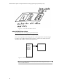
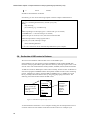
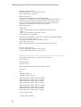
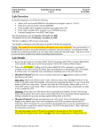
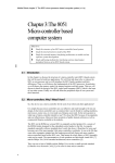
5.2. Overview of the 8031 SBC
The 8031 SBC board you use is a low cost, yet a powerful and comprehensive controller
card, it has the following interface modules.
The 8031 has timers and supports two external interrupt inputs.
Two 8255 chips on board will give you 48 bits of parallel IO bits,
Serial interface to talk to your PC through a MAX232 RS232 interface chip.
One watch dog timer MAX691
One real-time clock DS1287A to keep time and generate interrupt.
1
Mobile Robot chapter 5: Peripheral devices and programming experiments (v.2a)
8031 SBC
8031
CPU
Parallel
Ports
Two
8255
Watch
-dog
timer
AMX
691
48 digital
IO pins
Real-time clock
DS1287A
Figure 5. 1 An overview of peripheral devices of the SBC
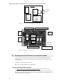
GAL 18GV8
MAX691 watchdog timer
RS232
LEDs
EPROM
8255
8255
8031
MAX23
SRAM
SRAM
RTC
7805 regulator
Two 8255
bus
connectors
LCD CONNECTOR
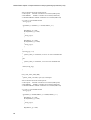
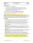
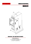
Figure 5. 2 Picture of the 8031RL SBC
5.3. Introducing the Peripheral devices to be used with the 8031
In this section we will discuss the ways of how to use a number of different useful
peripheral chips for the 8031, and illustrate how to utilize these devices through a series
of experiments.
Datasheets of these chips can be found at
http://www.cse.cuhk.edu.hk/~khwong/datasheets
Parallel input/output 8255s interface
See http://developer.intel.com/design/periphrl/INDEX.HTM for datasheet of 8255.
The SBC has two 8255 chips. Since each 8255 has 3 sets of 8-bit IO pins, therefore each
8255 has 24-bit IO bits. Thus the board has 48 bits of digital IO pins. Programming of the
8255 can be found in the data sheet.
2
Mobile Robot chapter 5: Peripheral devices and programming experiments (v.2a)
To make the system useful and be able to control our robot it should have a set of parallel
IO pins for our disposal. The 8031 has originally come with a set of 32 IO pins, however,
they are already used for memory interfaces and other important purposes such as serial
IO, timer etc. It left very little IO pins for our control work. One possible solution (and a
very popular one) is to add one or two parallel interface chips (8255) to our system. The
interfacing work is quite standard and the 8031 micro-controller has been designed to
have the interfacing pins ready for the connection. Such connection requires the host
system (a uP or an 8031) to control two address pins (A0 ,A1), 8-bit data , /CS , /WR and
/RD pins on the 8255.
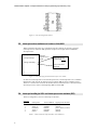
8-bit PortA
8255
/CS
A0,
A1
/RD,
/WR
Reg0
Reg1
8-bit Port B
Reg2
Reg3
8-bit PortC
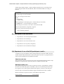
Figure 5. 3 Interface pins and registers of an 8255
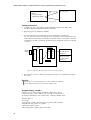
We adopt a method called memory mapped IO to connect the 8255 chips to 8031. The
method basically treats the 8255 registers (Reg0,1,2,3) as certain locations of data
memory and by writing to these particular locations, we can instruct the 8255 to function
as we wish. Data can also be read from three data ports of the 8255 by reading those
memory locations. But we do need to scarify something for that, which are some memory
address areas in our shared RAM/ROM space. The 8031Rl SBC chooses the Data space
E000-E003H and E800-E803H for these purposes. As you can see from the circuit
diagram the arrangement is to have /CS for the two 8255s connected to the address
decoder of address E000 and E800, also /WR and /RD are connected to the 8031 just as a
RAM. To avoid conflict between the 8255 sand RAM2, the chip select signal of RAM2 is
now A15 * A14 constraining the range inside 8000-DFFFH. The pity is we can never use
the RAM space between E000-FFFFH. Moreover space F000H is reserved for the LCD
display panel control which shall be discussed later.
A10-A14,
/PSEN,
/RD,/WR
of 8031
PEEL GAL
18GV8 used as
address decoder
/RD
/WR
A0,A1,
D0-D7,
Reset
3
/E00XH
/CS of 8255-U9
E000,E001,
E002,E003
/E80XH
/CS of 8255-U8
E800,E801,
E802,E803
Mobile Robot chapter 5: Peripheral devices and programming experiments (v.2a)
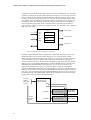
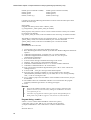
This diagram above shows the two 8255s located at E800 and E000 and have their /CSs
connected to the E800 and E000 decoder output, respectively. A0,A1, D0-D7, /RD, /WR,
RESET of the 8255s are all connected to their corresponding pins at the 8031.
To the 8031, a parallel interface chip is treated as four external data memory locations,
and each 825 has 3 sets of 8-bit input/output pins.
For example in 8255-U9, the four addresses E000, E001, E002, E003H are the four
registers Reg0, Reg1, Reg2, Reg3, respectively. The address decoding of these four
registers is similar that in CPU and memory interfacing. The upper address lines are fed
into the address decoder to form two chip select signals for addresses /E00XH and
/E800XH. That is, when an external data read/write instruction accessing addresses
E00XH is executed the /CS of 8255-U9 will be selected, and so on.
A summary of the functions of the 8255 registers is listed below. We can see that
occupies 4 locations. It is noted that PORTA of the 8255s are already connected to the
LEDS, so if PORTA is programmed to be output ports, we can use them as display
devices.
8255-U8 at 0xe800
0xE800 (port A-connected to LEDS)
0xE801 (port B)
0xE802 (port C)
0xE803 (control reg.)
8255at 0xe000
0xE000 (port A-connected to LEDS)
0xE001 (port B)
0xE002 (port C)
0xE003 (control reg.)
Table 5. 1 8255 address map
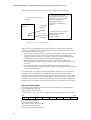
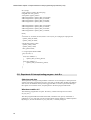
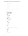
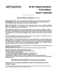
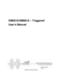
Watch dog timer MAX691, See the data sheet max691.pdf
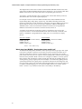
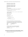
An external watch-dog-timer (MAX691) wakes up the processor by giving a reset signal
to the micro-controller if it doesn’t received any stop reset instruction from the microcontroller. That means you have to write explicitly in your program to give a regular
pulse (about 10ms interval) to an input bit of the watchdog timer. Otherwise the watchdog
timer will reset your SBC. What is the use of it? Imagine your SBC is a security system
that works day and night but has a small program loop that tells the watchdog timer it is
working fine by giving it regular pulses. For example, it is interfered by lighting that the
system hangs therefore no regular pulses is produced. Therefore the watchdog timer will
reset (by giving a pulse to the reset input of the 8031) the SBC to tell it to start again so as
to escape out of the hanging crisis. As a result the SBC resumes to its routine work as
before. Such is a very common scenario that is used widely in the Industry.
4
Mobile Robot chapter 5: Peripheral devices and programming experiments (v.2a)
At this stage our robot are not designed for 24-hour service yet so this watchdog timer is
not required. Perhaps a future non-stop robot that can search for a power source to
recharge its battery would find this watch-dog-timer very handy.
If the master (8051) does not pull
the string regularly, the dog
(MAX691) will press the reset
button to wake up the master.
8051
Sends
regular
signals to
the watchdog-timer
Reset
Button
If you don’t give me
signals, that means you
have already hanged,
then I will wake you up
by pressing the reset
button.
WATCHDO
MAX691
Figure 5. 4 To illustrate how the watch-dog-timer works
Real-time clock DS1287A
See ds12887.pdf (ds1287A is an old version of ds12887, so read ds12887A data sheet
instead).
A real-time clock, with an internal battery to keep it running, gives you the time readings
including years, months, days, hours, minutes and seconds. Not only does it give you the
correct time, it can also generate accuracy clock signals for various control functions.
Also some real time clock chips have batteries inside that enable the chips to run for 10
years.
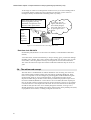
5.4. The add-on-card concept
This little 8031 is wonderful but not without limitations. For one thing, one of the two
8031 internal timers would be used by the serial link for generating Baud rates. Since
timer is so important in our robot design for generating pulse-width-modulation signals
for driving DC motor or servo (positional) motor, we do need more timers for our
disposal. Another thing is the 8031 itself is heavily loaded with peripheral chips such as
two 8255s and ROM, RAMS etc. if more devices are to be added, the 8031 outputs pins
may not be able to deliver enough currents for proper operations. One way to get round it
is to attach devices at the output side of the 8255. It is as if an external bus is developed
for add-on cards just like a PC. If we carefully design the hardware, it will give us a
flexible platform for not just adding more timers (8253) but also more parallel ports (8255)
or peripherals such as 8253s, or Analog-to-Digital converters etc.
5
Mobile Robot chapter 5: Peripheral devices and programming experiments (v.2a)
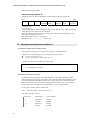
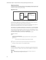
Figure 5. 5 A 8031 SBC with add-on card slots
added 8253/8254 interval timer
http://developer.intel.com/design/periphrl/INDEX.HTM
Look for the data sheet of 8254 for it is a superset of 8253.
It is a device to generate exact timing pulses for various applications. One main usage is
to produce pulse-width-modulated timing signals for the ultra-sonic radar system, the
servomotor and the direct-current motors for the robot.
8255
parallel
24-bit IO
PA0-PA7
PB0-PB7
PC0-PC7
8253 timer
Figure 5. 6: 8253 attached to the 8255
Exercise 5. 1 The 8255 has three 8-bit IO ports (total 24 bits). Design the interface
between the 8255 and 8253.
6
Mobile Robot chapter 5: Peripheral devices and programming experiments (v.2a)
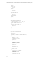
Figure 5. 7 The pin assignment of 8253
5.5. Interrupt service routines and vectors of the 8031
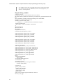
What is hardware interrupt? It is a method to ask the computer to execute a program
(interrupt service routine or ISR) upon the reception of a request from an hardware
interrupt source.
Main()
{ setup interrupt;
Interrupt
request source
signal
//doing something….
:
Interrupt service
routine ISR vector
:
:
reti (return from
interrupt
:
}
Figure 5. 8 The main program and an interrupt service routine
So what is an interrupt source? For the 8031 processor, an interrupt source is a condition
that the 8031 will execute an interrupt service routine (ISR) if such a condition occurs.
There are 5 such sources as shown in the table below, and each source is associated with
an interrupt vector, which is the beginning address of that ISR.
5.6. Interrupt handling in 8031 and interrupt service routines (ISR)
There are altogether 5 sources of interrupts to the 8031,
Interrupt
type #
0
1
2
3
4
Description
External 0
Timer 0
External 1
Timer 1
Serial
Vector Address
0x0003
0x000B
0x0013
0x001B
0x0023
Signal pin at the 8031
pin12 (/INT0) or P3.2
internal
pin13 (/INT1) or P3.3
internal
internal
Table 5. 2 The 5 8051 interrupts and their vector addresses
7
Mobile Robot chapter 5: Peripheral devices and programming experiments (v.2a)
(Serial IO: when a valid data is received or when a valid data is transmitted)
A “C” view of external int0
interrupt
Main program
Main()
{
…
…
…
Triggered by
Hardware
reti – return
from interrupt
}
/* Interrupt service routine
ISR with the name name_isr0
responses to external interrupt
int0 pin 0 (pin12, p3.2)
using register bank 2 */
void name_isr0 interrupt 0
using 2
{
…
…
} /* Will inset an “reti” return
from interrupt assembly
instruction here
by the compiler */
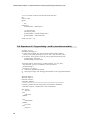
Figure 5. 9 A “C” view of external int0
When an interrupt condition appears (from one of the five interrupt sources) and the
system is programmed to allow such interrupt (by setting some bits in the IE, TP and
TCON registers of the 8031) to occur.
• Wait until the current instruction is finished. Note that PSW -- the flag register, ACC,
and other registers are not saved, the programmer needs to do the pushing and
popping of registers explicitly. (as contrast to the 80x86, which would do pushing
and popping of general registers automatically during ISR calls)
• Push the program counter to the stack (so that it knows how to comes back)
• Reload the program counter with the interrupt vector according to the source for the
interrupt.
• So it will execute the corresponding ISR, when the 8031 executes an RETI
instruction in the ISR, it will pop the main program return address from the stack and
return to the main program.
For each ISR call, it will jump to that particular address when the current instruction is
completed. The starting address corresponding to each interrupt request (or called
interrupt vectors) is hardwired that means you cannot change it. However, if some other
places are more convenient you may simply redirect it to other locations by a long jump
instruction. For example by putting a “ljump 8013H” at the starting address of particular
the ISR vector, say 0013H, it will finally reach 8013H as a result of that interrupt request.
Interrupt enable register
You may program the 8031 to accept or ignore certain interrupts by manipulating the
interrupt enable the register IE.
Register IE, 1=enable, 0=disable
For example in C, “IE = IE | 0x85” will enable all external interrupt sources (/int0, /int1)
Bit7
EA
Bit0
ES
--
--
EA = enable all interrupts
ES Serial interrupt enable bit
ET1 Timer overflow interrupt enable
EX1 External interrupt enable
ET0 Timer overflow interrupt enable
8
ET1
EX1
ET0
EX0
Mobile Robot chapter 5: Peripheral devices and programming experiments (v.2a)
EX0 External interrupt enable
Interrupt priority register IP
Interrupt priority can also be adjusted by using the interrupt priority register IP
Bit7
--
--
--
PS
PT1
Serial Port Timer1
PX1
PT0
External 1 Timer0
Bit0
PX0
External 0
1= high priority
0= low priority
A low priority ISR can be interrupted by a high priority ISR but not by a low priority ISR.
A high priority interrupt can not be interrupted.
If two same priority requests arrive at the same time, the internal polling sequence will
take effect, the polling sequence is:
IE0 TF0 IE1 TF1 -->>T1(serial)
High priority ------------------------ low priority
5.7. Writing the interrupt service routine in C
The SDCC interrupt service routine format
SDCC allows interrupt service routines to be coded in C using the format
void timer_isr (void) interrupt isr_type using register_bank_number
isr_type can either 0,1,2,3,4
register_bank_number can be either 0,1,2,3
A typical interrupt service routine will look like this.
void timer_isr (void) interrupt 2 using 1 //using interrupt 2 and register bank 1
{
……. “C” programming statements
}
Readjustment of interrupt vectors
As studied before the interrupt vector ISR addresses are at 0x0003, 0x000B, etc. But
some system may find it more convenient to have some other ISR starting addresses; such
as the PAULMON and 8031RL board that we are using. This issue will be explained in
detail in the next section. In light of this requirement, the SDCC allows you to readjust
the interrupt vector according to the starting address of your program address.
For example, in SDCC use the compile line
>sdcc --code-loc 0x8000 --main-return test_isr.c
will set the interrupt vectors to
Interrupt #
0
1
2
3
9
Description
External 0
Timer 0
External 1
Timer 1
Vector Address
0x8003
0x800B
0x8013
0x801B
Mobile Robot chapter 5: Peripheral devices and programming experiments (v.2a)
4
Serial
0x8023
See SDCC documentation for details.
In summary you can use the following template. And the compile command line is:
// compile line >Sdcc --code-loc 0x8000 --main-return test_isr.c
//test_isr.c containing both the main( ) and the your_isr2( )
Main()
{ setup interrupt;
//do something, e.g. an endless loop
:
}
//ISR responding to an interrupt type 2-> external int1 (pin-13 of 8031)
// INTERRUPT 2 -> external /int2 (pin-13 of 8031)
//when /int1(pin-13 of 8931) is low, 8031 will execute this ISR
//
//ISR interrupt number 2 using register bank 3
void your_isr2 (void) interrupt 2 using 3
{
//does something ISR does
:
} // an “reti” instruction will be automatically added here by the compiler.
5.8. Redirection oif ISR vectors in Paulmon
We will see how Paulmon redirects ISR vectors to the RAM2 space.
Since Paulmon2, our 8031 monitor program at EPROM, resides at 0000-7FFFH (8K)
locations of the program address space, therefore when any interrupt request occurs it will
execute some code inside Paulmon2 namely 0x0003, 0x000B, 0x0013,0x01B and 0x23H.
As ISRs are inside UV-ROM space it takes time to modify, because it takes 10 Minutes to
erase and reprogram an EPROM. Hence development of ISRs becomes a time consuming
process. Therefore we prefer to put these ISRs in RAMS space, i.e. RAM2. We can do
this by carefully redirect the ISR vectors by using long jump (ljmp) instructions. The
following is how PAULON2 redirect the ISR vectors.
0003H
ISR vector : entry
point of interrupt
type 0 for external
interrupt
/int0 (pin-12)
(Paulmon2
ROM)
8003H
:
reti
(data/prog.
SRAM)
SDCC
generated
interrupt type
0 routine
location
begins at
8003H
Figure 5. 10 Redirection of interrupt vectors
As discussed before the SDCC C-cross compiler actually puts the interrupt ISR vectors to
a location relative the start address of the desired code location. For example if you
10
Mobile Robot chapter 5: Peripheral devices and programming experiments (v.2a)
compile the program using the –code-loc 0x8000, the ISR vectors are relocated to the
place starting at 0x8000. So PAULMON2, SDCC and 8031RL SBC are working in
harmony.
For example:
//compile line: > sdcc test_isr0.c --code-loc 0x8000 --main-return
// the following isr will be at 0x8003
//test_isr0.c listing Iis shown below
main()
{ setup interrupt;
//endless loop
}
//ISR responding to an interrupt type 0-> external int0 (pin-12 of 8031)
// INTERRUPT 0 -> external /int0 (pin-12 of 8031)
//when /int0 (pin-12 of 8031) is low, 8031 will execute this ISR
//
//ISR: interrupt number 0, using bank 3 registers
void ext_int_isr0(void ) interrupt 0 using 3
{
//does something ISR does
}
5.9. Descriptions of the experiments
•
Experiment 41: Use of 8255 parallel interface
•
Experiment 42: Use of Interrupt
•
Experiment 43: Use of the real time clock
•
Experiment 44: Use of printf( ) and getch( )
•
Experiment 50: Use of xdata and serial port
5.10. Experiment 41: use of the 8255 parallel ports - test41.c
A simple test to get you familiar with the 8255 parallel ports of the 8031 SBC. However
students should study the datasheet of 8255 (8255.pdf) to learn how to program the 8255
control register and data ports for different IO modes.
Objectives and aims
This experiment is design to teach the use of the C development hardware/software setup.
Students are required to show particular patterns of LEDS on the 8031 SBC.
What does test41.c do?
The program shown below first creates a pointer lists for the C programmers to address
the 8255 control and data registers of the SBC. There are two 8255 chips and each chip
has 4 registers (one control register and three data registers, each for a 8-bit data port).
One 8255 chip is connected to the address begins at 0xe800 and the other at 0xe000.
Because each 8255 occupies 4 locations, so the address map becomes.
8255 at 0xe800
11
8255at 0xe000
Mobile Robot chapter 5: Peripheral devices and programming experiments (v.2a)
0xe800 (portA-connected to LEDS)
0xe801 (portB)
0xe802 (portC)
0xe803 (control reg.)
0xe000 (portA-connected to LEDS)
0xe001 (port B)
0xe002 (port C)
0xe003 (control reg.)
C pointers are used for addressing the hardware locations at the 8031 data space that is
used for the 8255 chips.
In the header,
unsigned char xdata *pointer name = address_inhex;
e.g. unsigned char _xdata *p8255_e800_cnt=0xe803;
In the program, what you have to do is to write to those locations as if they are variables
by pointer access methods.
E.g. *p8255_e800_cnt=0x80; //will write 0x80 into the control reg. of 0x8255 at 0xe803.
The LEDS are connected to the port A of the 8255 devices, so with revised convention.
*p8255_e000_a=0xff; //will turn off all LEDS at port A of 8255 at 0xe000.
*p8255_e000_a=0x00; //will turn on all LEDS at port A of 8255 at 0xe000.
Procedures
Download from PC to 8031-sbc
1.
2.
3.
4.
5.
6.
7.
8.
9.
10.
11.
12.
13.
14.
15.
Connect 8031-sbc to com2 using an RS232 serial cable
Run “Win98-Hyperterminal” from PC by double click Windows-Hyperterminal from
explorer
In Windows-Hyperterminal, “Transmit Text” is a useful commands
In Windows-Hyperterminal Set 9600,N,8,1,com2 etc. (use Alt-p to set
communication parameters)
Press reset at the 8031-sbc
You will see the message of Paulmon2 message on the screen.
paulmon: http://www.pjrc.com/tech/8051/index.html
In Paulmon command windows: Press “?” to see the available commands
In Paulmon command windows: “D” for download
Now you are back to Windows-Hyperterminal, press “Alt-S” select “ASCII” for
sending test41.ihx
You will see .., then get a message of download complete
Since the code is actually in 0x8000, so you can read the code or assembly
(disassembled by Paulmon2 I think), try “N” 8000; then “L” for viewing assembly
code , or “H” for viewing hex code.
Use “j” 8000 to jump to the start address of the executable code test41.ihx you just
downloaded.
The LEDS of 8031-sbc should blink and after a few seconds when the program
terminates, Paulmon2 goes back to its starting point again.
Done.
…
Exercise
•
Program the LEDS at 0xe800 to have a pattern of 0x01, and rotates this
pattern crosswise (or anti-clockwise) among the 8 LEDS at a rate about
2 new patterns per sec.
•
Learn how to program the control registers of the 8255 parallel port to
make portA=out, portB=in, upperC =out, lowerC=in, all in mode 0?
Program listing -- test41.c
//test41.c ver3.12 contains main and ISR for external /int1 (pin13)
// when /int1 (pin13) is low, ISR ext_int_isr2(void ) will be executed
//Compile command line> sdcc -main-return --code-loc 0x8000 test41.c
//
#include <8051.h>
12
Mobile Robot chapter 5: Peripheral devices and programming experiments (v.2a)
int i,a,temp;
//main_pattern is used in the main prog.
unsigned char main_pattern;
//setup 8255 register pointers
xdata unsigned char *p8255_e800_cnt=0xe803;
xdata unsigned char *p8255_e800_a=0xe800;
xdata unsigned char *p8255_e800_b=0xe801;
xdata unsigned char *p8255_e800_c=0xe802;
xdata unsigned char *p8255_e000_cnt=0xe003;
xdata unsigned char *p8255_e000_a=0xe000;
xdata unsigned char *p8255_e000_b=0xe001;
xdata unsigned char *p8255_e000_c=0xe002;
main()
{
// init 8255-A, cnt=0x80, all outs; 0x89=> PA=in,low_PC=in,high_PC=input,pb=out
*p8255_e800_cnt=0x80;
*p8255_e000_cnt=0x80;
//off all leds at p8255_e000
*p8255_e000_a=0xff;
*p8255_e800_a=0xff;
main_pattern=0x0f;
// a long loop that blinks LEDS
for(i=0;i<20;i++)
{
for(a=0;a<50000;a++)
{
*p8255_e000_a=main_pattern;
}
for(a=0;a<50000;a++)
{
*p8255_e000_a=0xff-main_pattern;
}
}
}
5.11. Experiment 42: interrupt testing program – test 42.c
Objectives and aims
This experiment is design to help students to learn the use of interrupt in a microprocessor
system. The testing program has two parts: one main () and the other an ISR. The students
will see how an hardware interrupt will trigger the SBC to execute a particular ISR upon
the request of an external source, and jump back to the main program afterwards.
What does test42.c do?
The following program has two parts: the main ( ) and the interrupt service routine
ext_int_isr2( ).
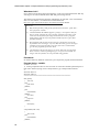
The main program blinks the LEDS of the SBC, and when /int1 (pin13) of the 8031 is
pulled low ext_int_isr2(void ) will be executed which sets the LEDS to a different pattern.
By doing so, we can see that the ext_int_isr2(void ) is actually being run.
13
Mobile Robot chapter 5: Peripheral devices and programming experiments (v.2a)
When /int1 is
low
Test42.c
Main()
{ setup interrupt;
//Blinks the LEDS
}
ext_int_isr2()
{
}
Figure 5. 11 The main and ISR of the testing progam
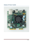
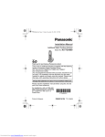
Testing procedures
1.
Compile test_isr2.c using SDCC and download the program to the SBC using
Windows-Hyperterminal and Paulmon2 commands.
2.
Run the program by jumping to 0x8000.
3.
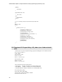
We know that when we connect /int1 (pin 13) of the 8031 to ground, then
ext_int_isr2(void ) will be executed. So for the experiment, wire-wrap pin13 of con3
with a thin wire and connect it to GND of con2 when test4.2.c is being run. (Note the
schematic of 8231RL is confusing; the following pin assignment is easier to read and
is correct.)
RS232
header
8
0
3
1
Con3
40
39
21
8031SBC
1
2
3
20
8
2
5
5
8
2
5
5
Pin-12 of con3
is /int0 (pin-12
of 8031)
Pin-13 of con3
is /int1 (pin-13
of 8031)
Con2
Figure 5. 12Showing the connection of the external interrupt pin.
4.
Record what you see: (a) before, (b) during and (c) after /int1 is pulled low. Explain
the result.
Exercise:
When /int1 is low and high again, we observed that the LEDS of
p8255_e800 always have a new pattern, explain why?
Program listing – test42.c
//test42.c ver3.12 contains main and ISR for external /int1 (pin13)
// when /int1 (pin13) is low, ISR ext_int_isr2(void ) will be executed
//Compile command line> sdcc –main-return --code-loc 0x8000 test42.c
//
#include <8051.h>
int i,a,temp;
//main_pattern is used in the main prog.; isr_pattern used in the ISR
unsigned char main_pattern, isr_pattern;
//setup 8255 register pointers
xdata unsigned char *p8255_e800_cnt=0xe803;
14
Mobile Robot chapter 5: Peripheral devices and programming experiments (v.2a)
xdata unsigned char *p8255_e800_a=0xe800;
xdata unsigned char *p8255_e800_b=0xe801;
xdata unsigned char *p8255_e800_c=0xe802;
xdata unsigned char *p8255_e000_cnt=0xe003;
xdata unsigned char *p8255_e000_a=0xe000;
xdata unsigned char *p8255_e000_b=0xe001;
xdata unsigned char *p8255_e000_c=0xe002;
main()
{
//SETUP INTERRUPT
//ie.7 global enable interrupt set; ie.2 external int. 1 set; ie.1 external int 0 set;
IE=IE | 0x85; //a very important step to initialize interrupt in the 8031
//set interrupt pin int1 active low (pin13 of 8031)
TCON= TCON | 0x01;
// init 8255-A, cnt=0x80, all outs; 0x89=> PA=in,low_PC=in,high_PC=input,pb=out
*p8255_e800_cnt=0x80;
*p8255_e000_cnt=0x80;
//off all leds at p8255_e000
*p8255_e000_a=0xff;
main_pattern=0x0f;
for(i=0;i<20;i++) // a long loop
{
for(a=0;a<50000;a++)
{
*p8255_e000_a=main_pattern;
}
for(a=0;a<50000;a++)
{
*p8255_e000_a=0xff-main_pattern;
}
}
}
// use interrupt 2 (external interrupt 1 pin13 of 8031) using register bank 1
// note: use interrupt 2 (external interrupt 1 pin13 of 8031) using register bank 1
//for the following statement 2 is interrupt number, using 1 means register bank 1
//if you use sdcc isr5.c -code-code 0x8000 -main-return, this ISR will be at 0x8013
//in Paulmon2 at 0x0013 long-jump lmp to 0x8013,
//address
code; jump from 0013 to 8013
// 0013
02 ;long jump ljmp
// 0014
80
// 0015
13
// it seems that if "using 1" is used, it cannot goes back to paulmon2
// it seems that if "using 2" is used, it can goes back to paulmon2
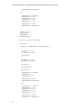
void ext_int_isr2(void ) interrupt 2 using 2
// (register bank 2)
{ isr_pattern++;
*p8255_e800_a=isr_pattern;
}
5.12. Experiment 43: Using the real time clock Dollas DS1287A – test43.c
Students should learn about the programming of the real time clock DS1287A
(ds12887a.pdf) before running this lab.
15
Mobile Robot chapter 5: Peripheral devices and programming experiments (v.2a)
Objectives and aims
To learn about real-time interrupt techniques. In this experiment a real-time clock is used
to generate a periodic time interrupt to the CPU. The advantage is to have control of the
occurrence of certain events at precise timing.
What does it do?
8031SBC
8031
pin12
(/int0)
Connected
already
Real-time clock
DS1287A
Pin19 (IRQ output)
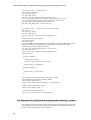
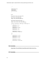
Figure 5. 13 The Real time clock generates a regular interrupt to the 8031
It is found that the /IRQ (pin19) of the DS1287 real time clock is already connected at
factory to the external interrupt request /int0 (pin12) of the 8031.
Therefore if we can program the real time clock to send out interrupt request signal at a
fixed time interrupt, the 8031 will serve out request at a regular basis.
The DS1287A has two different output mode for output signals: (1) to generate interrupt
every second, (2) to generate faster interrupt rate, we will use case (2) in our experiment.
You can see that at the main program, it reads the real time clock and display its time in
seconds through the LEDS. While in the ISR, each triggering will make enable a counter
to increment and the counter is also shown by the LED display.
Note that in the 8031 SBC the real time clock’s address begins at 0xec00.
Algorithm of Test43.c
Main()
{
Initialize 8255; interrupt setup;
Initialize real time clock interrupt signal generation mode to “pattern generator”
Endless loop
{
read second counter and display through LEDS of 0xe000 ;
}
}
ISR responses to periodic interrupt request (through. IRQ) of the real time clock
{
Increment a counter and show it to the LEDS at 0xe800;
}
Procedures
No need to make any hardware connection; just compile the program, download it and
test. But you need to use a DSO to observe the waveform of IRQ (pin 19 of DS1287A).
Exercise
•
16
Modify the program to make the interrupt counter LEDS count faster; it
can be done by increasing the interrupt rate.
Mobile Robot chapter 5: Peripheral devices and programming experiments (v.2a)
•
Use a DSO to observe the waveform of the interrupt request signal from
the real time clock (pin 19 of DS1287A) and record the frequency, is it
what you would expected?
Program listing – test43.c
/* test43.c ver3.12
testing of the real-time clock Dollas DS1287A (or 12887A)
No need to make any hardware connection; just compile the program, download it and
test.
Pin 19 of DS1287 is already connected to INT0 (pin-12 of 8031 SBC)
remember to set Interrupt pin active low
at 8031 by TCON= TCON | 0x01;
----- isrmain1.c ------, blink LED of the cache 8051sbc-computer
compile command line
>Sdcc test43.c --code-loc 0x8000 --main-return
*/
#include <8051.h>
#include <stdio.h>
int i,a,temp;
unsigned char time1,foo;
unsigned char pattern,pattern_count=1;
xdata unsigned char *p8255_e800_cnt=0xe803;
xdata unsigned char *p8255_e800_a=0xe800;
xdata unsigned char *p8255_e800_b=0xe801;
xdata unsigned char *p8255_e800_c=0xe802;
xdata unsigned char *p8255_e000_cnt=0xe003;
xdata unsigned char *p8255_e000_a=0xe000;
xdata unsigned char *p8255_e000_b=0xe001;
xdata unsigned char *p8255_e000_c=0xe002;
//realtime clock ds1287
xdata unsigned char *rtc_ec00_second=0xec00;
xdata unsigned char *rtc_ec01_second_alarm=0xec01;
xdata unsigned char *rtc_ec03_minute_alarm=0xec03;
xdata unsigned char *rtc_ec05_hour_alarm=0xec05;
xdata unsigned char *rtc_ec0a_rega=0xec0a;
xdata unsigned char *rtc_ec0b_regb=0xec0b;
xdata unsigned char *rtc_ec0c_regc=0xec0c;
xdata unsigned char *rtc_ec0d_regd=0xec0d;
main()
{//SETUP INTERRUPT
IE=IE | 0x85;
//ie.7 global enable interrupt set;
//ie.2 external int. 1 set;
//ie.1external int 0 set;
//set interrupt pin int1 active low (pin13 of 8031)
TCON= TCON | 0x01;
// init 8255-A
*p8255_e800_cnt=0x80;
*p8255_e000_cnt=0x80;
*p8255_e000_a=0xff;
*p8255_e800_a=0xff;
pattern=0x0f;
//read it once to make /irq(pin19 of ds1287) return to 1
foo=*rtc_ec0c_regc;
17
Mobile Robot chapter 5: Peripheral devices and programming experiments (v.2a)
/* for reference only :::::::interrupt-case-1
//set rtc alram-clock-mode
*rtc_ec0a_rega= 0x20;
*rtc_ec0b_regb= 0x20;
foo=*rtc_ec0c_regc; //make sure pin19 of ds21287 /irq=1
*rtc_ec01_second_alarm=0xff; //second don't care;interpt.every second
//*rtc_ec01_second_alarm=0x03; //int. every minures at the first 3sec
*rtc_ec03_minute_alarm=0xff; //minute is don't care
*rtc_ec05_hour_alarm=0xff; //hour is don't care
*/
/* for reference only :::::::interrupt-case-2; every-second type
//rtc registers
*rtc_ec0a_rega= 0x20;
*rtc_ec0b_regb= 0x10;
foo=*rtc_ec0c_regc; //make sure pin19 of ds21287 /irq=1
*/
//interrupt-case-3 periodic interrupt
//rtc registers setting
//*rtc_ec0a_rega=
//0x23 for 8192Hz; 0x24 for 4096Hz; 0x25 for 2048Hz; 0x26 for 1024Hz; 0x27 for 512
//0x28 for 256Hz;0x29 for 128Hz;0x2a for 64Hz;0x2b for 32Hz;0x2c for 16Hz;
//0x2d for 8 Hz; 0x2e for 4Hz; 0x2f for 2Hz;
*rtc_ec0a_rega= 0x2d; //0x20 for slower, l.s.b.-4bit =rate
*rtc_ec0b_regb= 0x40;
foo=*rtc_ec0c_regc; //make sure pin19 of ds21287 /irq=1
for(i=0;i<100;i++)
{
for(a=0;a<10000;a++)
{
//realtime clock testing
time1=*rtc_ec00_second; //read in second
*p8255_e000_a= (0xff-time1);
}
for(a=0;a<10000;a++)
{
*p8255_e000_a= (0xff - time1);
}
}
}
// use interrupt 0 (external /int0 [pin12 of 8031]) reg. bank 2
//for the following statement 2 is interrupt number,
//using 2 means register bank 2
void ext_int_isr2(void ) interrupt 0 using 2 // (register bank 2)
{
*p8255_e800_a=0xff - pattern_count;
pattern_count =pattern_count + 1;
//make sure pin19 of ds21287 /irq=1
foo=*rtc_ec0c_regc; //read it once to off interrupt
}
5.13. Experiment 44 : Use of putchar and getch (with some bug!) – test44.c
This experiment tests the use of for getting user information and displaying text, through
the standard input/output channel. It also teaches students to use line-line assembly and
the use of some external functions for Paulmon2.
18
Mobile Robot chapter 5: Peripheral devices and programming experiments (v.2a)
What does it do?
Get a character from the keyboard, and display it on the screen through the 8031 SBC. By
so doing we can send commands to the SBC and gets message from it.
This function uses the build in functions of Paulmon2, in particular “cout: lcall 0x0030”
and “cin: lcall 0x0032”, see Paulmon2 user build function at
http://www.pjrc.com/tech/8051/pm2_docs/functions.html for details.
Exercise:
1) Why do the putchar( ) and getch( ) functions need to have “push ACC”
and “pop ACC” inside?
2) I understand that the SDCC supports “printf( )” but requires that you
have a putch( ) function in your program. I attempt it in test45.c with
some success but found a few bugs as listed in the test45.c program
listing Please help me to fix the problem. Study reference [1] to find
possible solutions
3) Development code for atoi (ascii to integer). So that one can use the
keyboard to enter an integer, say 132, then this value goes to an integer
variable in your program. There are open free source code around,
give me the programs if you have them.
4) Development code for itoa (integer to ascii). Since the current printf
doesn’t seem to work on printing integers, so if you can translate an
integer into ascii format, one can print this using putchar.
Procedures
No need to make any hardware connection; just compile the program, download and test.
Program listing – test44.c
/*test44.c ver3.12
1) During compilation there is some error but its still works. Students please help me to
look into it and fix any bug if exits. Study reference [1] to find possible solutions.
*/
#include <8051.h>
#include <stdio.h>
/////////////////////////////////////////////////////////////////////////////////////////////////////
char getch()
{
char cin;
_asm
push ACC
_endasm;
_asm
lcall 0x0032 ;
_endasm;
cin=ACC;
_asm
pop ACC
_endasm;
return(cin);
}
void putchar(char cout)
{
ACC=cout;
_asm
lcall 0x0030 ;
_endasm;
19
Mobile Robot chapter 5: Peripheral devices and programming experiments (v.2a)
}
/////////////////main() must be at the bottom of all other files
int i;
char cin_char;
main()
{
do{
putchar('?');
putchar(0x20); // ASCII space
cin_char=getch();
putchar(cin_char);
putchar(0x0d); // ASCII carriage return
putchar(0x0a); // ASCII line feed
}
while( cin_char != 'q');
}
5.14. Experiment 45 : Program listing – test45.c (sometimes unstable)
/*test45.c ver3.12
I found that the bugs are:
1) It has some compiler error but still works under normal condition,
But if you are using interrupt by /int0, or /int1 it may not work, why?
2) "\n" doesn't work you have to put in your program the following lines
putchar(0x0a); //line feed
putchar(0x0d);//carriage return
3) message and %c cannot mix,e.g. printf("message , %c",cin_char);
does not work, you have to make it to two lines, such as
printf("message ")
printf("%c", cin_char);
5) scanf is not implemented I think
6) Cannot print integer %d. floating point numbers are not supported officially.
*/
#include <8051.h>
#include <stdio.h>
#include <serial.h>
//#include <stdlib.h>
/////////////////////////////////////////////////////////////////////////////////////////////////////
//external _pucthar function expected by serial.h used in Paulmon2
// #include <reg51.h> //needed, ACC is the accumulator
char getch()
{
char cin;
_asm
push ACC
_endasm;
_asm
lcall 0x0032 ;
_endasm;
cin=ACC;
_asm
pop ACC
20
Mobile Robot chapter 5: Peripheral devices and programming experiments (v.2a)
_endasm;
return(cin);
}
void putchar(char cout)
{
ACC=cout;
_asm
lcall 0x0030 ;
_endasm;
}
/////////////////main() must be at the bottom of all other files
int i;
char cin_char;
main()
{
while(cin_char != 'q')
{
printf("Press a button? \n");
putchar(0x0a); //line feed
putchar(0x0d);//carriage return
cin_char=getch();
printf("The character you entered is : ");
printf("%c", cin_char);
putchar(0x0a); //line feed
putchar(0x0d);//carriage return
printf("press any key to continue");
putchar(0x0a);
putchar(0x0d);
}
}
5.15. Experiment 50: Program listing – t50_xdata.c (use of xdata and serial
port)
/* test50 ver3.12 A more complete testing program, including the use of xdata and serial
port, is the t50_xdata.c */
/* t50_xdata.c
LED at p8255_e000
0x85=> no error
0x01 ==> error at test1
LED at p8255_e800
0x85=> no error
0x0f ==> error at test2
//for Cachecom 8031rl sbc board system
// code-eprom 0x0000-->0x7fff is at U5-27256(32K-eprom)
// data-XRAM
0x0000-->0x7fff is at U6-62256(32K-sram)
// code/data-XRAM 0x8000-->0xdfff is at U7-62256(32K-sram)
test1_xram_0000_7fff();
test2_code_xram_9000_dfff();
only two tests, cannot test 0x8000-->0x8fff
because this code will sit in.
21
Mobile Robot chapter 5: Peripheral devices and programming experiments (v.2a)
Program to show how to use
1) external 32K-byte sram of the 8031sbc and
2) the compile option "xram-loc"
Hardware requirment:
1) you must have the MAX691 (watch dog) on board
2) I suppect we can make it work even without the MAX691; the solution is
when the max-691 is removed, connect pin12 and 13 of the empty socket.
The test was performed but failed, however, we can think along this line,
refer to the circuit digram for the design of the board for
futher investigations.
compile line:
>Sdcc --code-loc 0x8000 --xram-loc 0x0000 --main-return test47.c
or simply
>Sdcc --code-loc 0x8000 --main-return test47.c
since defualt xram-loc is 0x0000
In general for the 8031SBC-rl you can use --xram-loc from 0x0000 to 0xd000
(e.g --xram-loc 0xc000), but your
user program in RAM is usally at 0x8000 so try not to
put two things at the same
address, the compiler does not care so you need to check for yourself.
after you run the program
//1 led (at e000 LEDs) turned on means wrong
//2 leds (at e000 LEDs) turned on means correct
*/
//===========================================================
//This program writes data into sram and read it back and see
//if it is ok or not
#include <8051.h>
#include <stdio.h>
xdata unsigned char td1[0xffff]; //from 0x8000-->0x7fff
long long_i;
int i,j;
unsigned int address_x;
unsigned char foo,wrong_tag;
xdata unsigned char *p8255_e800_cnt=0xe803;
xdata unsigned char *p8255_e800_a=0xe800;
xdata unsigned char *p8255_e800_b=0xe801;
xdata unsigned char *p8255_e800_c=0xe802;
xdata unsigned char *p8255_e000_cnt=0xe003;
xdata unsigned char *p8255_e000_a=0xe000;
xdata unsigned char *p8255_e000_b=0xe001;
xdata unsigned char *p8255_e000_c=0xe002;
test1_xram_0000_7fff()
{
*p8255_e000_cnt=0x80;
22
Mobile Robot chapter 5: Peripheral devices and programming experiments (v.2a)
//for Cachecom 8031rl sbc board system
// code-eprom 0x0000-->0x7fff is at U5-27256(32K-eprom)
// data-XRAM
0x0000-->0x7fff is at U6-62256(32K-sram)
// code/data-XRAM 0x8000-->0xdfff is at U7-62256(32K-sram)
//****test 1: xram 0x0000-0x7fff
wrong_tag=0;
for(address_x=0;address_x<=0x7fff; address_x++)
{
td1[address_x] = 0xff;
if( td1[address_x] !=0xff)
{
wrong_tag=1;
}
td1[address_x] = 0x00;
if( td1[address_x] !=0x00)
{
wrong_tag=1;
}
}
if(wrong_tag == 0)
{
*p8255_e000_a = 0xff-0x85; //correct for test1-ram0000-7fff
}
else
{
*p8255_e000_a = 0xff-0x01; //error for test1-ram0000-7fff
}
return(wrong_tag);
}
test2_code_xram_9000_dfff()
{
*p8255_e800_cnt=0x80; //port a,b,c all outputs
//for Cachecom 8031rl sbc board system
// code-eprom 0x0000-->0x7fff is at U5-27256(32K-eprom)
// data-XRAM
0x0000-->0x7fff is at U6-62256(32K-sram)
// code/data-XRAM 0x8000-->0xdfff is at U7-62256(32K-sram)
//****test 1: xram 0x0000-0x7fff
wrong_tag=0;
for(address_x=0x9000;address_x<=0xdfff; address_x++)
{
td1[address_x] = 0xff;
if( td1[address_x] !=0xff)
{
wrong_tag=1;
}
td1[address_x] = 0x00;
23
Mobile Robot chapter 5: Peripheral devices and programming experiments (v.2a)
if( td1[address_x] !=0x00)
{
wrong_tag=1;
}
}
if(wrong_tag == 0)
{
*p8255_e800_a = 0xff-0x85; //correct for test1-ram0000-7fff
}
else
{
*p8255_e800_a = 0xff-0x0f; //error for test1-ram0000-7fff
}
return(wrong_tag);
}
//external phex16 of Paulmon2
void phex16(unsigned int ii)
{
_asm
push DPL
push DPH
/*push R2
push R3
push R4
push R5*/
push PSW
_endasm;
DPL = (ii % 256);
DPH = (ii / 256);
_asm
lcall 0x0036 ;
_endasm;
_asm
pop PSW
/*pop R5
pop R4
pop R3
pop R2*/
pop DPH
pop DPL
_endasm;
}
//external _pucthar function expected by serial.h used in Paulmon2
// #include <reg51.h> //needed, ACC is the accumulator
char getch()
{
char cin;
_asm
push ACC
_endasm;
_asm
lcall 0x0032 ;
24
Mobile Robot chapter 5: Peripheral devices and programming experiments (v.2a)
_endasm;
cin=ACC;
_asm
pop ACC
_endasm;
return(cin);
}
void putchar(char cout)
{
ACC=cout;
_asm
lcall 0x0030 ;
_endasm;
}
delay(xdata unsigned int delay_t)
{ xdata unsigned int long del_x,del_y,del_foo1;
for(del_y=0;del_y<delay_t;del_y++)
{
for(del_x=0;del_x<20;del_x++)
{
del_foo1=0;
}
}
}
test3_com_out_xram_0000_7fff()
{
wrong_tag=0;
for(address_x=0;address_x<=0x7fff; address_x++)
{
td1[address_x] = 0xff;
if( td1[address_x] !=0xff)
{
wrong_tag=1;
}
td1[address_x] = 0x00;
if( td1[address_x] !=0x00)
{
wrong_tag=1;
}
phex16(address_x);
if(wrong_tag==0)
{
putchar(0x3d); //= 'equal sign'
putchar(0x4f); //= 'o'
putchar(0x4b); //= 'k'
putchar(0x0a); //new line
25
Mobile Robot chapter 5: Peripheral devices and programming experiments (v.2a)
putchar(0x0d);
}
else
{
putchar(0x3d);
putchar(0x46);
putchar(0x41);
putchar(0x49);
putchar(0x4c);
//carraige return
//= 'equal sign'
//= '46' F
//= '41' A
//= '49' I
//= '4c' L
putchar(0x0a); //new line
putchar(0x0d); //carraige return
}
}
phex16(wrong_tag);
putchar(0x0a);
putchar(0x0d);
return(wrong_tag);
}
test4_com_out_code_xram_9000_dfff()
{
wrong_tag=0;
for(address_x=0x9000;address_x<=0xdfff; address_x++)
{
td1[address_x] = 0xff;
if( td1[address_x] !=0xff)
{
wrong_tag=1;
}
td1[address_x] = 0x00;
if( td1[address_x] !=0x00)
{
wrong_tag=1;
}
phex16(address_x);
if(wrong_tag==0)
{
putchar(0x3d); //= 'equal sign'
putchar(0x4f); //= 'o'
putchar(0x4b); //= 'k'
putchar(0x0a); //new line
putchar(0x0d); //carraige return
}
else
{
putchar(0x3d);
putchar(0x46);
putchar(0x41);
putchar(0x49);
putchar(0x4c);
//= 'equal sign'
//= '46' F
//= '41' A
//= '49' I
//= '4c' L
putchar(0x0a); //new line
putchar(0x0d); //carraige return
26
Mobile Robot chapter 5: Peripheral devices and programming experiments (v.2a)
}
}
phex16(wrong_tag);
putchar(0x0a);
putchar(0x0d);
return(wrong_tag);
}
main()
{
unsigned char wtag1,wtag2,wtag3,wtag4;
//test and show result using LEDS
wtag1 = test1_xram_0000_7fff();
wtag2 = test2_code_xram_9000_dfff();
//test and show result using serial out
wtag3 = test3_com_out_xram_0000_7fff();
wtag4 = test4_com_out_code_xram_9000_dfff();
if(wtag1==0 && wtag2==0 && wtag3==0 && wtag4==0)
{
putchar(0x41); //= 'A'
putchar(0x4c); //= 'L'
putchar(0x4c); //= 'L'
putchar(0x20); //= 'space'
putchar(0x4f); //= 'O'
putchar(0x4b); //= 'K'
putchar(0x0a); //new line
putchar(0x0d); //carraige return
}
else
{
putchar(0x46);
putchar(0x41);
putchar(0x49);
putchar(0x4c);
//= '46' F
//= '41' A
//= '49' I
//= '4c' L
putchar(0x0a); //new line
putchar(0x0d); //carraige return
}
}
5.16. Conclusion
In this chapter we have studied the use of interrupt in 8031 and the use of various
peripheral devices such as the 8255 parallel interface device and the real time clock.
5.17. Conclusion
27
Mobile Robot chapter 5: Peripheral devices and programming experiments (v.2a)
5.18. References
1.
Official home of SDCC http://sdcc.sourceforge.net/
2.
Paulmon2 user manual http://www.pjrc.com/tech/8051/pm2_docs/commands.html
3.
SDCC manual : C compiler for 8031 SDCCUdoc.ps at
http://www.cse.cuhk.edu.hk/~khwong/ceg3430/ceg3430.htm
-- End of this chapter --
28
Mobile Robot chapter 5: Peripheral devices and programming experiments (v.2a)
29