1
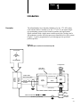
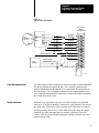
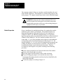
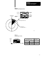
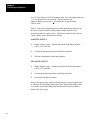
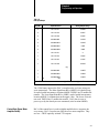
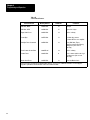
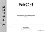
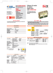
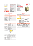
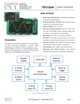
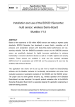
AllenBradley
Servo Interface
Module
(Cat. No. 1771-SF1)
User
Manual
Table of Contents
Introduction . . . . . . . . . . . . . . . . . . . . . . . . . . . . . . . . . . . .
11
Description . . . . . . . . . . . . . . . . . . . . . . . . . . . . . . . . . . . . . . . .
User Considerations . . . . . . . . . . . . . . . . . . . . . . . . . . . . . . . . . .
11
12
Component Interfacing, Module Preparation,
and Installation . . . . . . . . . . . . . . . . . . . . . . . . . . . . . .
21
General . . . . . . . . . . . . . . . . . . . . . . . . . . . . . . . . . . . . . . . . . . .
Component Interfacing . . . . . . . . . . . . . . . . . . . . . . . . . . . . . . . .
Encoder . . . . . . . . . . . . . . . . . . . . . . . . . . . . . . . . . . . . . . . . . .
Differential Line Drivers . . . . . . . . . . . . . . . . . . . . . . . . . . . . . . . .
Servo Drive Package . . . . . . . . . . . . . . . . . . . . . . . . . . . . . . . . .
Isolation . . . . . . . . . . . . . . . . . . . . . . . . . . . . . . . . . . . . . . . . . .
Wiring . . . . . . . . . . . . . . . . . . . . . . . . . . . . . . . . . . . . . . . . . . . .
Cable Recommendations . . . . . . . . . . . . . . . . . . . . . . . . . . . . . .
Shield Connection . . . . . . . . . . . . . . . . . . . . . . . . . . . . . . . . . . .
Module Preparation . . . . . . . . . . . . . . . . . . . . . . . . . . . . . . . . . .
Module Installation . . . . . . . . . . . . . . . . . . . . . . . . . . . . . . . . . . .
Keying . . . . . . . . . . . . . . . . . . . . . . . . . . . . . . . . . . . . . . . . . . .
Specifications . . . . . . . . . . . . . . . . . . . . . . . . . . . . . . . . . . . . . .
21
21
21
21
21
22
22
23
23
24
26
27
28
Programming and Operation . . . . . . . . . . . . . . . . . . . . . . .
31
General . . . . . . . . . . . . . . . . . . . . . . . . . . . . . . . . . . . . . . . . . . .
Data Transfers . . . . . . . . . . . . . . . . . . . . . . . . . . . . . . . . . . . . . .
DAC Data (Servo Motor Speed) . . . . . . . . . . . . . . . . . . . . . . . . .
Control Byte (Servo Motor Amplifier Inhibit) . . . . . . . . . . . . . . . . .
Encoder Counter Values (Position Pulses) . . . . . . . . . . . . . . . . . .
Target Values (Position Interrupts) . . . . . . . . . . . . . . . . . . . . . . . .
Special Servo Lines on the Backplane . . . . . . . . . . . . . . . . . . . . .
Marker . . . . . . . . . . . . . . . . . . . . . . . . . . . . . . . . . . . . . . . . . . .
A>B ............................................
CCW/CW . . . . . . . . . . . . . . . . . . . . . . . . . . . . . . . . . . . . . . . . .
Target Value Interrupt . . . . . . . . . . . . . . . . . . . . . . . . . . . . . . . . .
Programming the Servo Control Functions . . . . . . . . . . . . . . . . . .
31
31
31
33
34
34
34
35
35
35
35
35
Chapter
1
Introduction
Description
The Allen-Bradley Servo Interface Module (Cat. No. 1771-SF1) when
used with the Micro Controller (Cat. No. 1771-UC1) can control single
axis positioning systems such as found in machine tool applications.
When combined with a single motor variable speed drive package and a
full quadrature encoder, this microprocessor-controlled servo drive system
(Figure 1.1) can be programmed to cycle through precise speed and
position profiles.
Figure 1.1
Typical MicroprocessorBased Servo Control System
User Program
EPROM
Programming
Unit
Plug-in EPROM
ÉÉ
ÉÉ
ÉÉ
ÉÉ
ÉÉ
ÉÉ
ÉÉ
ÉÉ
ÉÉ
ÉÉ
User Application
Single-Motor
Drive Package
Amplifier Inhibit
1771UC1
Micro
Controller
1771SF1
Servo
Interface
Module
Controlled Power
Motor Current Inhibit
Velocity +- 10V
Servo
Amplifier
Return
Common
Drive
Shaft
Servo
Motor
Tach.
(Velocity Loop)
Channels A & B, Channels A & B, Marker, Marker
(Position Loop, 50KHz Max)
Shaft
Encoder
Differential
Line Driver
10399
11
Chapter 1
Introduction
User Considerations
12
Operating features described in this manual must be totally programmed
in the user software (Z-80A opcodes) of the accompanying micro
controller. The servo interface module has the capability to perform as
described, provided that the software of the micro controller has been
completely developed. The user must assume full responsibility for
performing all systems engineering, programming, and software support
associated with the micro controller/servo interface module and intended
application.
Chapter
2
Component Interfacing, Module Preparation, and
Installation
General
This chapter describes the necessary characteristics of user-provided
components, preparation and installation of the module and wiring
considerations. Refer to the Micro Controller Users Manual (Publication
No. 1771-6.5.5) for installation of the micro controller module.
Component Interfacing
The servo interface module must be compatible with other components of
the control system, including the differential line drivers, shaft encoder
and servo drive package containing the servo motor control amplifier.
Required characteristics of these components are stated below.
Encoder
An encoder should have the following characteristics for monitoring the
rotational direction and position of a drive shaft.
Full quadrature, 90o out of phase (typical).
Maximum frequency to the servo interface module is 50 KHz for
Channels A, B, and marker.
Differential Line Drivers
Line drivers with the following characteristics can be used to transmit
encoder quadrature pulses to the servo interface module.
Differential outputs for Channel A, Channel B, and marker.
TTL Source and Sink Currents = 15 mA max.
TTL Output Voltage = 2.4V (min.) high
= 0.6V (max.) low
Servo Drive Package
Outputs available to the servo motor control amplifier must be compatible
with the following control voltage and current levels.
TTL output to inhibit the motor current.
TTL output to turn OFF the servo drive amplifier.
TTL Output Voltage = 2.4V (min.) high
= 0.6V (max.) low
TTL Sink Current = 12 mA (max.)
21
Chapter 2
Component Interfacing, Module
Preparation, and Installation
TTL Source Current = 7.9mA @ 2.4V
+10 to -10V DC analog output for forward or reverse proportional
motor speed control.
Isolation
None of the terminals of the servo interface module are protected against
misapplication of AC, DC, or reverse DC.
CAUTION: Do not apply voltage or current sources to the
terminals of the servo interface module except those specified
for the terminals. Damage to the module may result.
If voltages are misapplied and damage is done to the terminal-side of the
module, the system-side including the data bus to the micro controller is
protected to 500V DC maximum isolation from the terminal side of the
module.
Wiring
22
The line drivers and the servo amplifier of the motor drive package should
be wired to the field wiring arm connector of the servo interface module
as shown in Figure 2.1.
Chapter 2
Component Interfacing, Module
Preparation, and Installation
Figure 2.1
Typical Connection Diagram
Servo Interface
Module
Field Wiring Arm
Full
Quadrature
Encoder
Channel A
TTL
Differential
Line
Driver
Channel A
Channel B
Channel B
Marker
Marker
1
2
3
4
5
6
7
Drive Current Inhibit
8
Servo
Amplifier
9
Amplifier On/Off
10
Analog Control, + 10V
11
Not Used
12
10401
Cable Recommendations
The cable distance between the servo interface module and the differential
line drivers should not exceed 40 feet. Use a twisted conductor pair
within a shielded braid (Belden #8761 or equivalent) for connections to
the line drivers. Use a 14 gauge conductor for the analog output to the
servo amplifier and make this connection as short as possible to minimize
the voltage drop in the cable.
Shield Connection
Belden 8761 or equivalent cable has a foil shield with a bare stranded
drain wire. The shield should be connected to earth ground at one end of
the cable only. This can be at the customer end of the cable or at an I/O
chassis mounting bolt or stud. At the other end of the cable, the shield
should be cut short and taped back to insulate it from any electrical
contact. This is to guard against unwanted radiated electrical noise and
ground current loops.
23
Chapter 2
Component Interfacing, Module
Preparation, and Installation
The common terminal of the servo interface module should not be used
for the shield connection. This terminal is a common with respect to the
analog output, TTL outputs and pull-up resistors on the differential inputs.
WARNING: Do not use the common terminal of the servo
interface module field wiring arm for the shield connection.
Unpredictable operation could occur with resulting damage to
equipment and/or injury to personnel.
Module Preparation
Prior to installation, the multiplication factor for counting the encoder
quadrature pulses must be set internally. The quadrature pulses are
transmitted through the differential line drivers to the terminals of
Channels A and B. An additional complementary set of equal but
logically opposite pulses are transmitted by the drivers to the terminals of
Channel A and Channel B. The servo interface module can be set to
count either 1, 2, or 4 of the quadrature pulse edges for each quadrature
set depending on the desired positioning precision (Figure 2.2). The
desired multiplier, x1, x2, or x4 can be set manually by inserting the pair
of Burg pin jumpers on selected pairs of terminals. The jumpers are
located on the printed circuit board inside the module. They are
accessible by removing the cover plates according to the following
procedure:
Remove the four slotted screws from the label-side of the module.
Remove the left and right cover plates.
Place the printed circuit board on a table, solder side down.
The pair of Burg pin jumpers are located in the center of the
component-side of the printed circuit board and are identified by the
labels JPR1 and JPR2.
Position the jumpers according to Figure 2.3.
24
Chapter 2
Component Interfacing, Module
Preparation, and Installation
Figure 2.2
Example Encoder Diagram (250 Line)
Encoder
Output
Channel A
Channel B
Counts
Decoded
on the
Module
X1
Marker Pulse
at 360 o
Quadrature
Multiplier
X2
X4
Single Encoder Line
250 Lines for
one rotation (360o
)
10403
Figure 2.3
Burg Pin Jumper Selection
Jumper
Labels
Jumper Setting
for x1 Multiplier
Jumper
Positions
JPR1
JPR2
Left 1
2
3
Right
Encoder Count
Multiplier
JPR1
1 + 2 (left)
JPR2
2 + 3 (right)
x1
2 + 3 (right)
1 + 2 (left)
x2
1 + 2 (left)
1 + 2 (left)
x4
10402
25
Chapter 2
Component Interfacing, Module
Preparation, and Installation
Module Installation
The module should be located in the I/O slot adjacent to the Micro
Controller (Cat. No. 1771-UC1). If located further down the rack,
propagation delays due to longer signal paths along the backplane could
degrade performance. High-speed communication between the micro
controller and servo interface module necessitates this location.
The servo interface module must be used with the micro controller. It
cannot operate with PC processors or adapters.
The servo interface module can be used in the same I/O rack with any of
the standard AC and DC 1771 I/O modules. However, it must not be used
in an I/O rack containing microprocessor-based I/O modules. The only
exceptions to this are the following microprocessor-based I/O modules
which do not interfere with the operation of the servo interface module.
8-Bit Analog Input Module (Cat. No. 1771-1E)
Encoder/Counter Module (Cat. No. 1771-IJ/IK)
CAUTION: The Servo Interface Module (Cat. No. 1771-SF1)
will operate only when paired with the Micro Controller (Cat.
No. 1771-UC1).
WARNING: Avoid placing microprocessor-based 1771 I/O
modules (except as noted) in the same I/O rack with the servo
interface module. Unpredictable operation could occur with
resulting damage to equipment and/or injury to personnel.
26
Chapter 2
Component Interfacing, Module
Preparation, and Installation
Keying
Plastic keying bands shipped with each I/O chassis provide an easy
method for keying and I/O slot to accept only one type of module. Use of
the keying bands is strongly recommended.
The module is slotted in two places on its rear edge. The position of the
keying bands on the backplane connector must correspond to the slots to
allow insertion of the module so that only the servo interface module will
fit in this slot.
Refer to Figure 2.4. Snap the keying bands on the upper backplane
connectors between these numbers printed on the backplane:
8 and 10
16 and 18
Needlenose pliers can be used to insert or remove keying bands.
Figure 2.4
Keying Diagram
First Backplane
Connector For
I/O Modules
Keying
Bands
2
4
6
8
10
12
14
16
18
20
22
24
26
28
30
32
34
36
2
4
6
8
10
12
14
16
18
20
22
24
26
28
30
32
34
36
First
Backplane
Connector
For I/O
Modules
27
Chapter 2
Component Interfacing, Module
Preparation, and Installation
Specifications
Counter
Input
Analog Output (Single Channel to Servo
Amplifier)
• Differential
• 10V to + 9.995V
• Full quadrature encoder
• 5mA to +5mA max.
Counter Range
Max. Cable Distance
• 025510
• Marker input is latched and
reset by user program.
• 40 ft. encoder input
• 40 ft. TTL output
• 5 ft. analog output
Max. Input Frequency
Ambient Temperature Rating
• 50 KHz, any channel
• Operational : 0o to 60o C (32o to 140oF)
• Storage : 40o to 85oC (40o to 185oF)
TTL Input/Output Voltage
• 0.6 V max. low voltage
Relative Humidity Rating
• 2.4 V min. high voltage
• 5% to 9% (without condensation)
TTL Input Current
• 15mA per line driver channel
(differential inputs only)
TTL Output Current
• 7.9mA @ 2.4V as source
• 12mA max. as sink
Number of TTL Outputs
• Two
28
Chapter
3
Programming and Operation
General
The servo interface module controls the operation of a single motor servo
drive package in accordance with commands received from the micro
controller. Outputs to the servo amplifier of the drive package include:
-10.000 to 9.995V analog output signal for proportional motor speed
and direction control.
A TTL output to limit the drive current from the servo amplifier to the
motor.
A TTL output signal to turn the servo amplifier ON or OFF.
The servo interface module also monitors motion by counting quadrature
pulses from a shaft encoder. The pulses represent the rotational position
of the encoder shaft or servo motor drive shaft. The servo interface
module sends an interrupt signal to the micro controller every time the
accumulated counts of quadrature pulses equal a preset target value. This
signal can be used to minimize the programming required to monitor and
control the position of the drive shaft.
Differential line drivers convert the single-ended encoder signal to
differential pulses for Channels A, B, and Marker of the module. The
driver also transmits a complement set of pulses (equal but logically
opposite) to Channel A, Channel B, and Marker channel.
Data Transfers
All data transfers between the micro controller and the servo interface
module take place over the normal I/O 8-bit data bus on the backplane of
the 1771 I/O rack. The transfer of each one of the following data bytes is
initiated by a separately addressed read or write instruction from the
micro controller. The enable commands are transmitted over the special
DSEN lines described in the Micro Controller User’s Manual (Publication
No. 1771-6.5.5).
DAC Data (Servo Motor Speed)
The servo interface module contains a Digital to Analog Converter (DAC)
that sends a 0 to +10V analog voltage to the servo amplifier of the motor
drive package. The voltage controls the speed and rotational direction of
the servo motor. The input to the DAC is a 12-bit binary number sent
from the micro controller that allows the speed and rotational direction of
the servo motor to be changed by user program. The DAC converts the
31
Chapter 3
Programming and Operation
lower 11 bits to the 0 to 10V DC analog output. Bit 12 designates the sign
+ or - for forward or reverse motion. The resolution of the
digital-to-analog conversion is +10V/2048 bits or approximately
4.883 mV/bit.
Table 3.A shows the relationship between the input binary number from
the micro controller and the analog output voltage from the servo
interface module for sample values. The binary number for any desired
output voltage can be determined as follows:
POSITIVE OUTPUT
1.
Output voltage (volts) ” decimal equivalent of the binary number.
4.883 x 10⁻³ (volts/bit)
2.
Convert the decimal equivalent to the binary number.
3.
Take the complement of the binary number.
NEGATIVE OUTPUT
1.
Output Voltage (volts) ” decimal equivalent of the binary number.
4.883 x 10⁻³ (volts/bit)
2.
Convert the decimal equivalent to the binary number.
3.
Add 1 bit to the binary number.
Refer to the rpm/voltage chart provided by the servo motor manufacturer
to complete the relationship between the DAC input binary number and
servo motor speed and to determine the direction of rotation which is
indicated by the sign bit.
32
Chapter 3
Programming and Operation
Table 3.A
DAC Input/Output
Sign Bit
Input Bit Pattern
Analog Output Voltage
0
111 1111 1111
10.000V
0
111 1111 1110
9.995V
0
111 1111 1100
9.990V
0
000 0000 0011
19.5mV
0
000 0000 0010
14.6mV
0
000 0000 0001
9.7mV
0
000 0000 0000
4.9mV
1
111 1111 1111
0
1
111 1111 1110
+4.9mV
1
111 1111 1101
+9.7mV
1
111 1111 1100
+14.6mV
(1)
1
000 0000 0011
+9.985V
1
000 0000 0001
+9.990V
000 0000 0000
(3)
+9.995V
1
(2)
(1) LowTRUE Bit Patterns
(2)= MSBY
(3) = LSBY
The 12 bit binary input to the DAC is transferred to two bytes using two
write instructions. The Most Significant BYte (MSBY) is eight bits long.
It can be loaded into memory location 600EH. DSEN Line 16 enables the
transfer. The Least Significant BYte (LSBY) can be loaded into memory
location 600DH. It contains data in the upper 4 bits. The lower 4 bits are
not used. DSEN line 15 enables the transfer. DAC data is reset at
power-up or by the data byte reset command (write location 600BH).
Control Byte (Servo Motor
Amplifier Inhibit)
Bit 2 of the control byte is used to inhibit amplifier drive current to the
servo motor. Bit 3 is used to turn OFF the servo motor amplifier. They
are low = TRUE optically isolated TTL outputs.
33
Chapter 3
Programming and Operation
A write instruction to memory location 600FH latches these bits. DSEN
Line 17 enables the transfer from the servo interface module. The control
byte is reset at power-up or whenever the data byte reset command is
programmed.
Encoder Counter Values
(Position Pulses)
The encoder line drivers generate pulses for each encoder line. Assume
that a 250 line encoder is used as in Figure 2.2. When the quadrature
multiplier is x1, a counter increment of 1 means that the encoder shaft has
turned through 1.44o. (This can be translated into the linear movement of
a feed slide, proportional to the number of drive shaft threads per inch.)
When either the x2 or x4 quadrature multiplier is used, one count is
equivalent to a turn of .72o or .36o, respectively.
The micro controller can be programmed to read the accumulated value of
the encoder counters in the servo interface module by a read instruction
from memory location 6008H. A read from the encoder counters is
usually performed when the encoder is halted or turning very slowly. A
read from this location does not halt counter operation. DSEN Line 10
enables the transfer from the servo interface module. The encoder
accumulated value is set to zero at power-up and after 255 counts. It also
can be set to zero by the counter reset command which is a write to
location 6009H.
Target Values (Position
Interrupts)
The target value determines at which count (in the accumulated count of
encoder pulses) an interrupt will be sent to the micro controller. The
target value is an 8-bit comparator preset ranging from 0-255. Target
value interrupts can be counted to monitor and control the rotational
position of the drive shaft.
A write instruction to memory location 600CH latches the target value.
DSEN Line 14 enables the transfer from the micro controller to the servo
interface module. The target value preset is reset to zero at power-up or
by the data byte reset command (write location 600BH).
Special Servo Lines on the
Backplane
34
Four special backplane lines are used to monitor servo signals at the micro
controller. The first three lines transmit the marker, A>B, and CCW/CW
signals, respectively, to the status port of the micro controller. They are
read at memory address 7000H. These signals are always on-line. The
fourth line transmits the interrupts to the micro controller.
Chapter 3
Programming and Operation
Marker
A low = TRUE signal is transmitted to status port bit 0 after the marker
signal is latched by the servo interface module for each completed
revolution of the encoder shaft. A write instruction to 600AH will reset
this latched output.
A>B
A low = TRUE signal appears at status port bit 1 whenever the target
value (preset) is greater than the accumulated value of the counters
counting the encoder pulses. The bit goes high when the accumulated
value becomes equal to or greater than the target value.
CCW/CW
Generally, a low signal appears at status port bit 2 when the rotation of the
encoder shaft is counterclockwise (CCW). A high signal will then
indicate clockwise (CW) rotation. This relationship depends on system
hardware and/or wiring polarity.
Target Value Interrupt
Whenever the accumulated value of the encoder counter becomes equal to
the target value preset, an interrupt signal is sent to the micro controller.
The vectored interrupt is generated by the counter/timer circuit (CTC
Channel 2) in the micro controller. The interrupt condition is
automatically reset by the micro controller during execution of the return
from interrupt instruction (RETI). The micro controller must be
programmed to perform this function.
Programming the Servo Control
Functions
The servo interface module controls the drive package in accordance with
commands received from the micro controller module. All programming
of the micro controller is written in the Z-80 instruction set. In order to
transfer the information described in Paragraph 3.1 from or to the servo
interface module, certain memory addresses have to be accessed in the
micro controller.
Whenever a Z-80 instruction is written to or read from a control function
address for the servo interface module, the instruction will force low one
of the corresponding special enable lines, DSEN 10-17. This signal
instructs the servo interface module to latch data received from the 8-bit
bidirectional backplane data bus (system write) or to place data on the
data bus (system read). The control functions, their addresses and
corresponding DSEN lines are tabulated in Table 3.B.
35
Chapter 3
Programming and Operation
Table 3.B
Servo Control Features
Control Function
Memory Address
DSEN Line
Comments
DAC Data, MSBY
600EH Write
16
8bit byte
DAC Data, LSBY
600DH Write
15
Upper 4 bits of byte
Target Value Preset
600CH Write
14
025510 in binary
Control Byte
600FH Write
17
Bit 2 limits drive current .
Bit 3 turns OFF the servo amplifier.
Data Byte Reset Command
600BH Write
13
Resets DAC data, Target
Value Preset and Control Byte by
loading zeros (Also reset at
powerup)
Read Counter Accum Value
6008H Read
10
025510 in binary
Counter Reset
6009H Write
11
Resets counters and decoder logic
by loading zeros (Also reset at
powerup).
Marker Latch Reset
600AH Write
12
Resets the Marker Latch
Refer to the Micro Controller Users Manual (Publication No. 17716.5.5) for additional information on developing the
program to perform the various functions of the servo interface module.
36
AllenBradley, a Rockwell Automation Business, has been helping its customers improve pro
ductivity and quality for more than 90 years. We design, manufacture and support a broad range
of automation products worldwide. They include logic processors, power and motion control
devices, operator interfaces, sensors and a variety of software. Rockwell is one of the worlds
leading technology companies.
Worldwide representation.
Argentina • Australia • Austria • Bahrain • Belgium • Brazil • Bulgaria • Canada • Chile • China, PRC • Colombia • Costa Rica • Croatia • Cyprus • Czech Republic •
Denmark • Ecuador • Egypt • El Salvador • Finland • France • Germany • Greece • Guatemala • Honduras • Hong Kong • Hungary • Iceland • India • Indonesia •
Ireland • Israel • Italy • Jamaica • Japan • Jordan • Korea • Kuwait • Lebanon • Malaysia • Mexico • Netherlands • New Zealand • Norway • Pakistan • Peru •
Philippines • Poland • Portugal • Puerto Rico • Qatar • Romania • RussiaCIS • Saudi Arabia • Singapore • Slovakia • Slovenia • South Africa, Republic • Spain •
Sweden • Switzerland • Taiwan • Thailand • Turkey • United Arab Emirates • United Kingdom • United States • Uruguay • Venezuela • Yugoslavia
AllenBradley Headquarters, 1201 South Second Street, Milwaukee, WI 53204 USA, Tel: (1) 414 3822000 Fax: (1) 414 3824444
Publication 1771-6.5.14 - February, 1983
Supersedes 1771-821 - September, 1983
PN 955089-98A
Copyright 1986 AllenBradley Company, Inc. Printed in USA
Publication 1771-6.5.14 - February, 1983