1
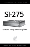
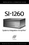
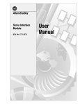
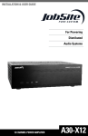
INSTALLATION
&
OPERATION
GUIDE
Systems Integration Amplifier™
®
B
L E N D I N G
H
I G H
F
I D E L I T Y
A N D
A
R C H I T E C T U R E®
CONGRATULATIONS!
Thank you for purchasing the Niles SI-275, one of the most flexible and convenient amplifiers ever offered. Like all Niles products, the SI-275 is built to the
highest standards of quality control and reliability. With proper installation and
operation, you'll enjoy years of trouble-free use.
Niles manufactures the industry's most complete line of custom installation components and accessories for audio/video systems. For a free full line catalog write:
Niles, Catalog Request, P.O. Box 160818, Miami, Florida 33116-0818
TABLE OF CONTENTS
INTRODUCTION
2
FEATURES AND BENEFITS
3
INSTALLATION CONSIDERATIONS
5
INSTALLATION
FRONT AND REAR PANEL DETAILS
1
11
9
OPERATION
15
TROUBLESHOOTING GUIDE
16
SPECIFICATIONS
18
The SI-275 is a member of the award-winning Niles Systems Integration Amplifier
family. It is designed for home theaters and whole house audio systems requiring
high power. Niles specifically created Systems Integration Amplifiers to solve the
problems of interfacing with different brands and models of equipment, different
acoustic environments in different rooms, and different kinds of applications;
home theater, stereo, and background music. The SI-275 brings extremely highcurrent power to a custom installed A/V System in a remarkably convenient way.
INTRODUCTION
INTRODUCTION
SI-275
Systems Integration
Stereo Power Amplifier
2
FEATURES AND BENEFITS
FEATURES AND BENEFITS
Real World Power
The SI-275 delivers 75 watts per channel at 8 Ohms and 100 watts per channel at
4 Ohms. You’ll get tremendous bass and dynamics from every pair of speakers
powered by an SI-275.
Transparent Sound
The audio circuitry of the SI-275 is constructed using the finest parts available;
including 1% metal film resistors, high quality capacitors, and oversized heat sinks.
All this attention to technical detail creates a sound that is clear and uncolored with
phenomenal imaging.
Freedom From Crosstalk
Each channel of the SI-275 is powered via its own independent power supply. This
increases the isolation between the two channels, and eliminates cross talk guaranteeing you absolute silence as the backdrop to your music.
Current For Reactive Loads
The high current design of the SI-275 assures that even unusual and reactive loads are
handled with aplomb. A massive toroidal transformer with two separate windings for
each of the power supplies supplies more than ample current to your system.
Freedom from Fan Noise
The oversized heat sinks inside the SI-275 allow the amplifier to stay cool even when
operating into low impedance loads—without the noise of fan-cooled amplifiers.
Independent Level Controls
Each channel has its own independent level control enabling you to precisely
match the SI-275 to the rest of your system. The level controls also enable you to
limit the volume, preventing abuse of the system.
Lifetime Connections
The SI-275 features gold plated stereo inputs, the cascade stereo outputs as well as the
five way binding posts are gold plated to ensure perfect connections without corrosion
for years to come.
3
The SI-275 features three turn-on modes: 1. Music Sense 2. External Voltage Trigger
3. Manual Turn-On via the front panel switch. You can configure the
SI-275 to interface with any kind of system and have the unit automatically turn on.
Automatic Protection
The SI-275 is equipped with sophisticated protection circuits. In the unlikely event
that a problem occurs, the amplifier shuts itself off. When conditions return to normal, regular operation resumes.
FEATURES AND BENEFITS
Turn-On Modes
Status Display for Troubleshooting
LED's on the front panel indicate Power, Active Status, and a Protection Warning. With
a glance at the front panel, a troubleshooter is quickly provided with key information!
Control Output
A 12 volt DC output is provided whenever the amplifier is on, allowing you to
operate voltage-triggered devices like motorized screens and curtains.
Designed and Engineered in the USA
Limited two year parts and labor Warranty.
4
INSTALLATION CONSIDERATIONS
INSTALLATION CONSIDERATIONS
Placement
Place the SI-275 on a flat level surface like a table or shelf. It should be placed
upright so that its weight rests on the four attached feet. Placing the weight of the
amplifier on the rear or front panel for even an instant will result in damage to the
amplifier's connectors and controls.
The SI-275, like any hi-fi component, will last much longer if it is given adequate
ventilation for proper cooling. When installing the SI-275 in a cabinet, be sure
that the rear of the cabinet is open to fresh air to provide proper cooling (see
Figure 1). If the cabinet’s design will not accommodate an open rear, install two
small “boxer fans” to provide continuous air flow into and out of the cabinet (see
Figure 2). Place the SI-275 so that there is at least 5" of free air space above the
chassis. If the amplifier is located on a carpeted surface, place a board under the
amplifier's feet. Do not block the ventilation holes on the top and bottom of the
SI-275.
The SI-275 is equipped with an internal transformer, which generates a powerful
magnetic field which could induce hum in a turntable (particularly a turntable
equipped with a moving coil cartridge). Do not place a turntable directly above
or directly adjacent to the SI-275.
Figure 1
Figure 2
If the cabinet rear is not open to
fresh air, install two small “boxer
fans” to provide continuous air
flow into and out of the cabinet.
Make sure that there is a minimum
of 5” of free air space above the
amplifier for proper ventilation.
Allow a minimum of 2” of
depth behind unit to accommodate cables and connectors.
5
The SI-275 draws more current than a preamplifier’s switched AC outlet can safely supply. Also, your preamplifier may "thump" at dangerous volumes if the
amplifier is already on when the preamp turns on. It is usually best to turn the
amplifier on only when it is needed. The Turn-On Mode selector switch gives you
three options for turning the SI-275 on and off.
INSTALLATION CONSIDERATIONS
Turn-On Modes
Constant - The auto turn-on circuitry is off. The front panel master power switch
operates the amplifier. In is "On", out is "Off".
Audio Sense - The master switch on the front panel must be in the "On" position.
The amplifier is off when there is no audio signal present at either the left or the
right input, but the sensing circuitry is on. The turn-on sensing circuitry looks for
a tiny amount of audio signal present at any of the audio inputs. If it detects a signal, the amplifier is turned on. Once the audio signal stops, the sensing circuit
waits two minutes, then turns the amplifier off.
3-30 Volt AC/DC Opto-Isolated Voltage Trigger - The master switch on the front
panel must be in the "On" position. The amplifier is off when there is no 3-30V AC
or DC voltage detected at the trigger input. Once the sensing circuitry detects a voltage, the amplifier is turned on. Once the voltage stops, the sensing circuit instantly
turns the amplifier off. Voltage triggers can be supplied by Niles automated switchers, some video projectors, some surround sound processors, or something as simple as a 16 volt AC wall adapter (Niles XF00008) plugged into the switched outlet
of your stereo receiver. DO NOT USE A DC WALL ADAPTER. The long discharge
time of the DC adapter’s filter capacitor will delay the turn-off of the amplifier.
If you are using a wall adapter or external power supply to provide the trigger, it
doesn't have to be very large (a minimum current capability of 2.5 milliamps for a
3 volt trigger increasing up to a minimum of 38 milliamps for a 30 volt trigger).
6
INSTALLATION CONSIDERATIONS
Multiple Speaker Loads
The SI-275 is stable into very low impedance loads. This means you can safely
operate three pairs of 8 ohm speakers (a 2.67 ohm load) directly connected to the
SI-275. Note that the SI-275 does not have on/off speaker switching built in.
When the amplifier is on, so are all of the speakers.
Niles makes a number of different speaker selection and impedance matching systems.
Speaker selection systems allow each pair of speakers to be turned on and off from your
equipment location (or even via remote control). That way, you know that the speakers in the bedroom are off so you can avoid waking a sleeping spouse! These speaker selectors provide an easy way to terminate all of the wires for more than three pairs.
Testing and troubleshooting a new system is much easier with the individual room
labels and on/off switches of a Niles speaker selection system. Additionally, Niles
speaker selection systems offer impedance matching features which will allow you to
connect up to ten pairs of speakers to your SI-275 amplifier.
Niles SI-275
Niles HDL-6 Speaker Selection System
AMPLIFIER
L+
L-
R-
SPEAKER 6
R+
L+
L-
R-
SPEAKER 5
R+
L+
L-
R-
SPEAKER 4
R+
L+
L-
R-
SPEAKER 3
R+
L+
L-
R-
SPEAKER 2
R+
L+
L-
R-
SPEAKER 1
R+
L+
L-
R-
R+
ON OFF
NILES
Niles Audio
Corporation, Inc.
CONSTANT
PROTECTION
Miami, Florida USA
Speaker selection systems allow each pair of speakers to be turned on and off from your
equipment location (or even via remote control).
7
It will be easier to reconfigure or troubleshoot your system in the future if you
label the cables and wires for their destination or source, rather than which terminal of the SI-275 they are connected to.
The SI-275 connects to your sources via shielded line level audio cables with
RCA phono plugs. Use high quality cables with your Niles amplifier for the lowest possible noise and best overall performance. Your Niles dealer can recommend the proper cable.
The SI-275 connects to your speakers using 2 conductor speaker wire. For most
applications, we recommend you use 16 or 18 gauge wire. For wiring runs longer
than 80 feet, we recommend 14 gauge wire. The binding posts of the
SI-275 will accommodate up to 12 gauge wire. Larger sizes can be accommodated
by attaching banana plugs to the wire. Note that the binding posts accept dual
banana or single banana connectors.
INSTALLATION CONSIDERATIONS
Cable and Wire
TECH TIP
Wire size is expressed by its AWG (American
Wire Gauge) number. The lower the number, the
larger the wire, i.e. twelve AWG is physically
larger than fourteen AWG.
8
FRONT AND REAR PANEL DETAILS
Red “Power” LED confirms the amplifier is
connected to a live AC power outlet. (and
that the master power switch is on).
Red “Active” LED lights when the amplifier circuitry has been turned on by the
Turn-On circuits.
Front panel “Master Power” switch turns
off the entire amplifier, including the
Turn-On circuitry.
The red “Protect” LED indicates the amp has shut
down because there is a fault in the speaker, the
wiring, or with the SI-275 itself.
Main Inputs enable you to route a stereo
line level source to the SI-275.
Cascade Outputs of the main input enable
you to daisy chain multiple amplifiers.
"Turn-On Mode" switch
3.5 Mini Plug socket
for voltage input.
3.5mm Mini Plug socket for
12v DC Control output.
9
FRONT AND REAR PANEL DETAILS
Level Adjustment screws enable you to preset
the maximum system volume (or match levels
with another amplifier).
Binding posts for speaker connections.
IEC receptacle for AC
power cord.
10
INSTALLATION
INSTALLATION
9 Setting The Turn-On Mode Switch
13 Cascade Audio Outputs
9 Control Output
14 AC Power plug
10 Speaker Wire Connections
17 Rail Fuse Holders
13 Line Level Audio Inputs
Setting the Turn-On Mode Switch
The SI-275 has three turn-on modes. Select which mode you desire by sliding the
mode switch. See Installation Considerations on page 6 for more information
about each of the turn-on modes.
Slide the switch with your fingernail or a
1/8” slotted screwdriver blade.
Control Output
This terminal provides a 12v DC signal suitable for triggering Niles automated switchers,
some motorized screens, some electric curtain
controls, etc. The trigger voltage is present
only when the amplifier is active or "on".
When the amplifier turns "off", the 12 volt signal is off.
11
Using the
3.5 mm jack.
STEP
DESCRIPTION
1. Check the requirements of the
device you want to control.
The control output has a maximum
current capability of 12vDC 150 mA.
2. Connect the 3.5mm Jack to the
control output maintaining proper
polarity (tip = +)
Niles makes an accessory cable
plug FG00724.
CAUTION! All speaker wire connections must be made with the amplifier Off.
Bare Wire
Unscrew the red or
black plastic knob,
insert the bare wire
end into the opening,
and then tighten the
knob until the wire is
securely clamped.
Banana Plugs
There are many types
of banana plugs, some
crimp, some solder.
The Niles gold banana
plug has a quick-connect binding post for
the bare wire on the
body of the plug. A
banana plug is simply
inserted into the jack
at the end of the amplifier’s binding post.
Dual banana plugs
will fit the SI-275 binding posts.
STEP
DESCRIPTION
1. Label all wires.
If you label the wires for their destination,
rather than which terminal of the SI-275 they
are connected to, it will be easier to reconfigure your system in the future.
2. Connect one stripped wire end or
banana plug to the black terminal
and one to the red terminal.
A. Split the speaker wire insulation so that
at least two inches of each conductor are
separated.
INSTALLATION
Speaker Wire Connections
B. Strip one half inch of insulation from the
end of each conductor of the speaker wire
CAUTION- Avoid even a single strand
of wire touching the chassis or another
connector.
C. Attach banana plugs or twist the strands of
wire together and insert them into the appropriate binding post.
12
INSTALLATION
Line Level Audio Input
CAUTION! THE AMPLIFIER MUST BE OFF WHENEVER YOU MAKE CHANGES
TO THE INPUT CONNECTIONS.
STEP
DESCRIPTION
1. Label all of the interconnecting
cables for the sources they connect to.
Use audio patch cables with RCA phono
plugs attached to the ends.
2. Connect the sources by inserting the
RCA plugs into the amplifier’s jacks.
Connect outputs from your sources to
inputs on the amplifier. Never connect a
source or preamplifier’s input (e.g., record
inputs) to the inputs of your SI-275.
Cascade Audio Outputs
The "Cascade Audio Outputs" enable you to connect another amplifier to your
preamplifier output. The connectors are gold-plated RCA phono jacks. Connect
them to another amplifier’s inputs with a standard audio patch cable. The outputs
are not buffered; if you wish to daisy-chain more than 5 Niles amplifiers you will
need a Niles ADA-6 buffered distribution amplifier. A single ADA-6 will allow
you to daisy-chain 5 amplifiers from each of its six outputs, allowing 30 SI-275
power amplifiers to be fed from the same master preamplifier. If your preamp has
a vacuum tube output stage, you must use a Niles ADA-6 to drive more than a
single SI-275.
13
STEP
DESCRIPTION
Plug the female IEC socket of the supplied AC cord into the IEC receptacle
on the rear of the amplifier.
Just like a computer or printer, the SI-275
has an AC cord which unplugs either at the
amp or at the wall for your convenience.
Plug the 2 prong plug into a correctly
grounded 120V 60 Hz wall outlet.
If you use a grounded power strip, surge
suppressor or extension cord, verify that
proper ground is maintained.
CAUTION! Typically the
preamp/receiver’s switched outlet is
not rated for a power amplifier.
The SI-275 draws a maximum of approximately 700 watts from an AC wall outlet.
Use the auto turn on circuit instead.
INSTALLATION
AC Power Plug
14
OPERATION
OPERATION
Power Switch
The front panel switch is a master or "vacation" power switch. No matter which
turn-on mode you have selected, the master power switch will turn off all circuitry—including the sensing circuitry. If you will not be using the amplifier for
an extended period of time, turn the master power switch "Off" (push button
switch out). When you would like to return to normal operation, turn the switch
"On" (push button switch in).
Power LED
The power LED indicates that the AC cord is plugged into a working AC power
receptacle and that the power switch is in the "On" position.
Active LED
The rear panel turn-on mode switch determines when and how the amplifier will
turn on. The "Active" LED indicates that the amplifier is operating.
Protection LED
The front panel protection LED indicates that the amplifier has been shut down
because of either a fault in the wiring or the speaker, or with the SI-275 itself.
Level Adjustment Screws
The front panel level adjustment screws allow you to adjust the level of the
SI-275 relative to other amplifiers in your system. Use a 1/8” slotted screwdriver
to adjust the screws. If the SI-275 is the only amplifier in your system, leave the
screws at their factory default position (turned fully clockwise).
Cleaning and Maintenance
The internal parts of the SI-275 are electronic and require no maintenance. Once
a year it is appropriate to twist the RCA connectors on each input to remove corrosion and improve conductivity.
You can clean the amplifier with soft cloth or paper towel dampened with water or
a mild detergent. Do not use any spray-type, abrasive cleaners on the amplifier.
15
When there is a problem consult this guide first. If the problem persists, or you
have additional questions, call your local Niles dealer or Niles Technical Support
at 1-800-289-4434. The most common problems relate to hook up. Call from
your telephone extension nearest the system.
SYMPTOM
POSSIBLE CAUSES AND TEST PROCEDURE
No sound on one channel
Short circuit or loose wire at the speaker or amplifier terminals. Check that the connections are secure
and that there are no loose strands of wire crossing
from the positive to the negative terminals at the
back of the amplifier and /or the speaker.
TROUBLESHOOTING GUIDE
TROUBLESHOOTING GUIDE
Short circuit or a break in the speaker wire. Disconnect the speaker wire at both ends, separate the
2 conductors at both ends and test with a meter for
a short circuit. If there is no short, connect the two
conductors at one end and test with a meter for
continuity.
Speaker is not working. Connect the speaker to a
channel that plays another speaker.
Audio cable to input is bad. Connect another cable
that is known to be good.
No sound on both channels
Audio cable to the main inputs is bad. Connect
another cable that is known to be good.
Hum from the speakers
Hum may be caused by a ground loop between
two of the other components in the system. To test
for another ground loop, try reversing the AC plugs
of each of the components in the system.
16
TROUBLESHOOTING GUIDE
17
TROUBLESHOOTING GUIDE (continued)
SYMPTOM
POSSIBLE CAUSES AND TEST PROCEDURE
Hum from the speakers
Check for faulty cables, faulty source material, an
ungrounded phono system or a defective component.
Amp will not turn on
AC power cord must be plugged into a working outlet.
Master power switch must be on.
Bass sound is weak and
the stereo image is
"phasey" or "blurry"
sounding in one room
The loudspeakers are wired out of phase. Reverse
the connections at the back of one speaker.
Design Principle
Linear voltage/current amplification.
Continuous Average Power Output
75 watts per channel RMS at 8 ohms.
100 watts per channel RMS at 4 ohms.
SPECIFICATIONS
SPECIFICATIONS
Input Impedance
56K ohms
Input Sensitivity
.985V for 8Ω rated output
Overall Voltage Gain
30 dB
Frequency Response
Bandwidth Limited from 10 Hz to 100 kHz
Total Harmonic Distortion
8 Ohms
.05% THD from 20 Hz to 20 kHz @ full rated power
4 Ohms
.06% THD from 20 Hz to 20 kHz @ full rated power
Overall Dimensions
17” wide 4” high (including feet) 13-1/8” deep
Weight
21 lbs
18
Niles Audio
Corporation
www.nilesaudio.com
12331 S.W. 130 Street
Miami, Florida 33186
Tel: (305) 238-4373
Fax: (305) 238-0185
©1999 Niles Audio Corporation. Because Niles strives to continuously improve its
products, Niles reserves the right to change product specifications without notice.
Niles, the Niles logo and Blending High Fidelity and Architecture are registered
trademarks of Niles Audio Corporation. Systems Integration Amplifier and
BusMatrix are trademarks of Niles Audio Corporation Printed in the USA 7/98
DS00219B