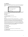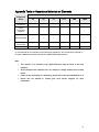
1
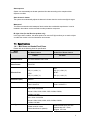
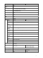
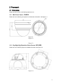
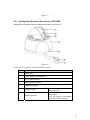
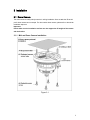
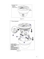
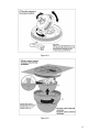
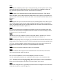
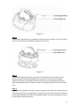
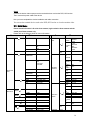
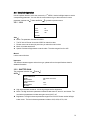
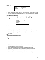
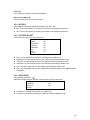
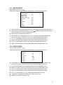
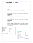
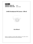
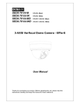
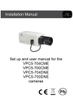
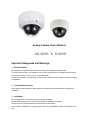
Analog Camera User’s Manual AD-960H & D-960H Important Safeguards and Warnings 1.Electrical safety All installation and operation here should conform to your local electrical safety codes. The power shall conform to the requirement in the SELV (Safety Extra Low Voltage) and the Limited power source is rated 12V DC (24V AC) in the IEC60950-1. We assume no liability or responsibility for all the fires or electrical shock caused by improper handling or installation. 2.Transportation security Heavy stress, violent vibration or water splash are not allowed during transportation, storage and installation. 3.Installation Do not apply power to the camera before completing installation. Please install the proper power cut-off device during the installation connection. Always follow the instruction guide the manufacturer recommended. If this product is installed in the ceiling, please make sure the installation position can sustain the min 50N. 4.Qualified engineers needed All the examination and repair work should be done by the qualified service engineers. We are not liable for any problems caused by unauthorized modifications or attempted repair. 5.Environment This series camera should be installed in a cool, dry place away from direct sunlight or strong light, inflammable, explosive substances and etc. The working temperature ranges from -10℃ ~ to +60℃. Please keep it away from the electromagnetic radiation object and environment. Please keep the sound ventilation. Do not allow the water and other liquid falling into the camera. 6. Accessories Be sure to use all the accessories recommended by manufacturer. Before installation, please open the package and check all the components are included. Contact your local retailer ASAP if something is broken in your package. 7. Daily Maintenance Please shut down the device and then unplug the power cable before you begin daily maintenance work. Use the dry soft cloth to clean the device. If there is too much dust, please use the water to dilute the mild detergent first and then use it to clean the device. Finally use the dry cloth to clean the device. Please put the dustproof cap to protect the CCD (CMOS) component when you do not use the camera. 1 General Introduction 1.1 Overview This series analog camera adopts the high sensitivity CCD and advanced circuit design. It is featuring the high quality video, the lowest distortion, low noise and etc. This series product is suitable to be used in surveillance system and video process system. 1.2 Features z z z z z z z z z z High-performance SONY CCD, high resolution, vivid and impressive video Support auto day/night mode switch to realize the monitor both in the daytime and at night. Support backlight compensation function (BLC) Support auto white balance function. Restore high definition and more reliable video High signal to noise ratio (SNR), clear and impressive video, The auto electronic shutter is suitable for various surveillance environments. Support auto electronic gain control, self-adaptive brightness. Auto exposure function Support IR function (For IR series product only) Advanced X-Y-Z axis structure, support the 355 degrees rotation.(For dome camera series product only) 1.3 Functions Day/night mode (Color and black/white switch) This function allows the camera to display the color video in the daytime while the black and white video at the night. It is to enhance camera sensitivity and definition. ICR The IR cut removal is to filter the IR light in the daytime and then auto switch to the general fitter at night. This function allows the camera to output the high sensitivity and clear video. Auto gain function To output the standard video signal in the different illumination environments, the amplifier needs to adjust in a wide range. The system can enhance the camera sensitivity in low illumination and enhance the video signal output to get the clear and high definition video. SNR It is the ratio value between the signal voltage and the noise voltage. The higher the SNR value, the lower the adverse effect. It is to guarantee the clear video. Auto White Balance The white balance refers to the camera to restore the white object color. It allows the camera to automatically adjust the color temperature in indoor and outdoor environment, just like our human eyes does. 3 Auto exposure System can automatically set shutter speed and iris value according to the snapshot video exposure condition. Auto electronic shutter The system can automatically adjust the electronic shutter when the environment light changes. Waterproof This series construction shell waterproof level reaches the considerable requirement. It can be installed in the outdoor environment without other protection component. IR night vision (for the IR series product only) In the night vision condition, this series product can use the IR light to allow you to see the object or realize the monitor in the low illumination environment. 1.4 Specifications 1.4.1 Mini Dome and Vandal Proof Dome Please refer to the following sheet for specification. Model Mini Dome Camera Parameter D-960H Video Processor 1/3" SONY EXview HAD Ⅱ CCD Video Format PAL/NTSC PAL: 976(H)×582(V) Effective Pixel NTSC: 976(H)×494(V) Resolution (PAL) Min Illumination Electronic Shutter Vandal Proof Dome Camera AD-960H PAL: 976(H)×582(V) NTSC: 976(H)×494(V) 960x576 Color:0.1Lux/F1.2 Color: 0.05lux/F1.4 PAL Auto: 1/50s~1/100,000s Manual: 1/50s,1/120s,1/250s,1/500,1/1000s,1/2000s, 1/4000s,1/10,000s NTSC Auto: 1/60s~1/100,000s Manual: 1/60s,1/100s,1/250s,1/500,1/1000s,1/2000s, 1/4000s,1/10,000s Lens Type Default model is 3.6mm. (2.8mm/6mm/8mm is optional) Default model isφ14 port auto aperture lens 2.8~12mm, Support ICR lens 4 Day/Night Switch Synchronization Mode Video Output SNR Auto INT 1Vp-p Composite Output (75 Ohm/BNC) Above 60 dB(AGC OFF) White Balance Gain Control Auto Auto BLC Auto OSD Menu Control Support LENS Manual SHUTTER/AGC Auto/Manual BACKLIGHT Off/BLC/HLC(High light compensation ) OSD DC (BLC) WHITE ATW/ ANTI CR /manual/push lock/push/user 1/user 2 BALANCE DAY/NIGHT Auto/external trigger/black and white/color MODE PICTURE Mirror/brightness/contrast/sharpness/hue/gain ADJUST ATR Off/luminance/contrast MOTION Detect sensitivity/block display/area selection DETECT PRIVACY Area selection/color/transparent/mosaic MASK NR Level/Y level/C level Camera ID Character/position Language English/Japanese and etc Working Temperature -30℃~60℃ Power DC12V±10% DC12V±10% (-A) series product support AC24V±10% ∕DC12V±10%. Power Consumption 3W MAX Dimension(mm) φ105×86.3 φ160×118.5 Weight 350g 1000g 5 2 Framework 2.1 Dimensions Please note all the units in the following figures are mm. 2.1.1 Mini Dome Camera D-960H Please refer to the following two figures for the dimension information. See Figure 2-1. Figure 2-1 Figure 2-2 Figure 2-3 2.1.2 Day/Night High Resolution Dome Camera AD-960H Please refer to the following figures for detailed information. See Figure 2-4. Figure 2-4 6 2.2 Structure 2.2.1 Mini Dome D-960H Please refer to the following figure for detailed information. See Figure 2-5. Figure 2-5 2.2.2 Dome Camera Please refer to the following figure for detailed information. See Figure 2-6. Figure 2-6 SN 1 Name Device lens N/A 2 Dome camera enclosure N/A 3 Dome camera side enclosure 4 Dome camera pedestal 5 Power input port 6 Video output port 7 Photosensitive component 8 IR light N/A For the dome camera (Figure 2-6), please turn the device upside down to see the pedestal. Connect to the DC 12V power to input the power. BNC port is to output analog video signal. You can connect to the devices such as the DVR or the NVR It is to control the IR light on/off status according to the environment illumination. It is to send out the IR compensation light to enhance the night vision. Important For the dome camera, there are two cable exits, one is at the bottom and one is at the side. Please use the rubber dustproof plug to secure the idle exit. The power cable and the video output cable both pull through the cable exit. 7 Figure 2-7 2.2.3 Day/Night High Resolution Dome Camera AD-960H Please refer to the following figure for detailed information. See Figure 2-8. Figure 2-8 Please refer to the following sheet for detailed information. SN Name 1 Device lens 2 Dome camera inside enclosure 3 X-Y-Z rotation module 4 Dome camera enclosure 5 Installation pedestal 6 Power input port 7 Power output port Connect to the DC 12+ power to input the power. BNC port. It is to output analog video signal. You can connect to the devices such as the DVR or the NVR 8 3 Installation 3.1 Dome Camera The dome camera usually mainly uses the in-ceiling installation. Here we take the IR vandal proof dome camera as an example. For other series dome camera, please refer to the similar installation steps too. Important Please make sure the installation surface can min support the 3X weight of the camera and the bracket. 3.1.1 Mini and Dome Camera Installation Figure 3-1 9 Figure 3-2 Figure 3-3 10 Figure 3-4 Figure 3-5 11 Step1 Please take the installation position map in the accessories bag, and then paste it on the ceiling or the wall you want to install the dome camera. Dig four holes in the installation surface and then insert four expansion bolts in the hole. Secure these four bolts firmly. Step 2 Turn the dome camera external enclosure counter clockwise and the remove. Push the two sides of the dome camera internal enclosure (Please refer to C6 in Figure 3-3) so that the hook drops from the X-Y-Z axis module. Remove the dome camera internal enclosure. Please refer to Figure 3-3. Step 3 Use the proper tool to open the cable exit side hole in the pedestal (Please refer to B2 in Figure 3-2), and then draw the cable from the cable exit (Please refer to B2 in Figure 3-2) and fix the cable in the pedestal cable channel. Draw the cable port out of the cable channel side hole of the pedestal (Please refer to the B2 in Figure 3-2 ). Step 4 Line up the four screw holes in the pedestal to the holes you just dug in the ceiling (wall), then input the four secure screws in the pedestal screw secure holes. Fix the screws firmly to secure the dome camera in the ceiling (wall). Step 5 Turn the lens or the ring to adjust the camera to the proper direction. Adjust the X-Y-Z axis to turn the camera lens to the proper monitor angle. Please refer to the Figure 3-4. Step 6 Push the hooks (Please refer to C4 in Figure 3-3) of two sides of the internal enclosure to the slot (Please refer to C5 in Figure 3-3) of the X-Y-Z axis to make the internal enclosure perfectly fit the X-Y-Z axis. After the installation, please make sure the lens port of the internal enclosure is fit the camera lens. Please refer to Figure 3-5 for proper adjustment if necessary. Step 7 Turn dome camera enclosure clockwise to fasten it on the pedestal. Step 8 Connect the device video output port to the terminal devices such as the DVR, NVS and etc. Then connect the power cable to the device. Now you have completed the dome camera installation and cable connection. You can use the terminal devices such as the DVR, NVS and etc to view the monitor video. 3.1.2 Vandal Proof and Day/Night High Resolution Dome Camera Installation Please note the following figures are based on the vandal proof dome camera. Step 1 Use the inner hexagonal wrench (provided) to loose the three inner hexagon screws in the dome cover and then open the cover. See Figure 3-6. 12 Figure 3-6 Step 2 Use the inner hexagonal wrench (provided) to loose the three inner hexagon screws in the dome and then remove the device installation pedestal. See Figure 3-7. Figure 3-7 Step 3 Take out the installation positioning map from the accessories bag and then paste it on the ceiling or the wall to identify the installation area. Draw out the cable exit and four plastic expansion bolt holes in the installation position according to the device pedestal. Dig the four plastic expansion bolt holes and cable exit. Insert the four plastic expansion bolts into the screw holes Step 4 Adjust the device installation pedestal to the proper position and then draw the cable through the cable exit you just dug in the ceiling (wall). Line up the four screw holes in the device pedestal to the four plastic expansion bolt holes in the installation position. Put the four self-tapping screws in the four plastic expansion bolts firmly. 13 Step 5 Adjust the device position and then line up the three inner hexagon screws of the device to the three holes in the installation ceiling (wall). Put the three inner hexagon screws to the screw holes of the device pedestal and then use the inner hexagonal wrench to secure firmly. Figure 3-8 Step 6 Push the two sides of the inside enclosure of the dome to remove the tab (D2). Loose the fixed screws (D4) and then turn the X-Y-Z rotation module (D3) to adjust the camera lens to the proper monitor angle. See Figure 3-9. Figure 3-9 14 Step 7 Put the done inside enclosure back and then put the dome cover back. Line up the three inner hexagon screws to the holes of the device. Use the inner hexagonal wrench to secure the screws to complete the installation. See Figure 3-10. Figure 3-10 3.2 Fixed Camera Here we take the 50M IR water proof fixed camera as an example. For other series fixed camera, please refer to the similar installation steps too. Important Please make sure the installation surface can min support the 3X weight of the camera and the bracket. Please refer to the steps listed below for installation information. Step 1 Line up the two installation holes at the bottom of the device shell to the two installation holes of the pendant bracket (in the front). Insert the screws and then secure firmly. Now you have fastened the device in the bracket. Figure 3-11 Step 2 Dig four holes in the wall (or ceiling) and then insert the four expansion bolts into the holes. Fix these bolts. Step 3 Line up the four screw holes at the bottom of the pendant bracket to the four installation holes you just dug in the wall (or ceiling). Insert the four screws into the four holes of the bracket (at the bottom). Finally you can secure the bracket in the wall (or ceiling). 15 Step 4 Connect the device video output port to the terminal devices such as the DVR, NVS and etc. Then connect the power cable to the device. Now you have completed the device installation and cable connection. You can use the terminal devices such as the DVR, NVS and etc to view the monitor video. 3.3 Main Menu Please note this function is for mini dome camera, high resolution dome camera and the vandal proof dome camera only. Please refer to the following sheet for menu information. st ND THE 1 MENU THE 2 LENS TYPE AUTO st MENU THE 1 MENU DC,VIDEO ATR MODE ON AUTO. ON, OFF ND THE 2 LUMIN ANCE LOW MIDDLE HIGH CONTR AST LOW MIDLOW MID MIDHIGH HIGH SPEED MANUAL AUTO OFF HIGH LUMINANCE MODE BRIGHTNESS SHUTTER AGC LOW LUMINANCE MODE MANUAL BRIGHTNESS MODE SHUTTER AGC SHUTTER+AUTO IRIS AUTO IRIS SHUTTER 0-255 MOTION DETECT ON DETEC T SENSE 000-127 BLOCK DISPLA Y MONIT OR AREA AREA SEL ON/OFF/SET TOP AUTO GAIN OFF ×0.25~×1.00 SHUTTER+AGC 1/50~1/10,000 6.00~44.80 BOTTO M LEFT RIGHT USER1 B-GAIN 0-255 USER2 R-GAIN B-GAIN R-GAIN 0-255 0-255 0-255 LEVEL 018-040 SPEED DELAY CNT ATW FRAME 0-255 0-255 ×0.50~×2.00 ANTI CR AREA SEL PRIVACY MASK ON PUSH LOCK MANUAL ON OFF 1/4-1/4 000-288 000-288 000-288 000-288 OFF TOP WHITE BALANCE MENU BOTTO M LEFT RIGHT COLOR TRANS PAREN T MOSAI C 1/4~4/4 000~288 000~288 000~468 000~468 1~8 0.00~1.00 ON OFF PUSH ATW OFF DAY/NIG AUTO BURST ON 16 OFF ENVIRON MENT INDOOR OUTDOOR DELAY CNT DAY→ NIGHT NIGHT →DAY OFF BACKLIG HT HT BLC HLC PICT ADJUST SYNC LANGUA GE CAMERA RESET B/W BRIGHTNESS CONTRAST 0-255 0-255 SHARPNESS 0-255 HUE 0-255 GAIN 0-255 BURST 000-255 000-255 000-255 ON OFF COLOR NR MODE Y LEVEL C LEVEL NR OFF,Y/C, Y, C 000-015 000-015 ON INT CAMERA ID ENGLISH OFF 3.4 Main Interface Press the menu button for 2 seconds; you can see the OSD menu appear in the monitor. MENU MENU LENS AUTO PRIVACY MASK OFF SHUTTER⁄AGC AUTO DAY/NIGHT AUTO WHITE BALANCE ATW NR BACKLIGHT OFF CAMERA ID OFF SYNC INT ENGLISH PICT ADJUST ATR OFF LANGUAGE MOTION DETECT OFF CAMERA RESET NEXT EXIT BACK SAVE ALL EXIT SAVE ALL 17 3.5 Detailed Operation Use the up/down button to move the cursor to the 1ST MENU, Use the left/right button to set the corresponding parameter. You can click the confirm button to go to the sub-menu if current parameter checked with . Select the BACK to go back to previous menu. 3.5.1 LENS AUTO IRIS TYPE DC MODE AUTO SPEED 080 RETURN Auto z Mode: The parameter includes DC/VIDEO. The DC is the DC auto iris and the VIDEO is video drive lens. Please connect to the auto iris port when you select the auto iris lens. z Mode: It includes auto/on/off. z Speed: Click the left/right button to set the value. The value ranges from 0 to 255. Manual It is the manual iris lens. Important: The different cameras support various lens type, please refer to the specifications sheet for detailed information. 3.5.2 SHUTTER GAIN The parameter includes: auto , manual . AUTO AUTO SETUP HIGH LUMINANCE MODE BRIGHTNESS LOW LUMINANCE MODE BRIGHTNESS RETURN SHUTTER+AUTO IRIS 028 AGC ×1.00 z z High luminance/low luminance: It is the high brightness/low brightness. Mode: The high luminance parameter includes shutter+auto iris, auto iris, and shutter. The low luminance parameter includes auto gain control (AGC), off. z Brightness: The high luminance parameter ranges from 0 to 255. Please use the left/right button to set. The low luminance parameter includes ×0.25,×0.50,×0.75,×1.00. 18 Manual MANUAL SETUP MODE SHUTTER AGC RETURN SHUTTER+AGC 1⁄50 6.00 z Shutter: The parameter includes 1/50, 1/120, 1/250, 1/500, 1/1000, 1/2000, 1/4000, 1/10,000. z Auto gain: The parameter includes 6.00, 12.00, 18.00, 24.00, 30.00, 36.00, 42.00, and 44.80. 3.5.3 WHITE BALANCE (WB) The parameter includes: manual , anti cr, push lock, user1 , user2 , ATW . Manual MANUAL WB LEVEL UP LEVEL DOWN PRESET RETURN User1 z z USER1 WB B-GAIN 030 R-GAIN 033 B-gain: It is to adjust the blue gain. Please use the left/right button to set. The value ranges from 0 to 255. R-gain: It is to adjust the red gain. Please use the left/right button to set. The value ranges from 0 to 255. Note: The user2 setup is the same with the user1. ATW ATW SPEED 239 DELAY CNT 003 ATW FRAME ×1.00 ENVIRONMENT INDOOR RETURN z z ATW: It is the auto trace white balance. The camera can adjust the color temperature according to the actual color hue environments. Speed: The value ranges from 0 to 255. Please use the left/right button to set. Delay control: The value ranges from 0 to 255.Please use the left/right button to set. z ATW frame: The parameter includes ×0.50、×1.00、×1.50、×2.00. z Environment: The parameter includes: indoor, outdoor. Please use the left/right button to set. z 19 Push lock It is to click the OK button to lock the white balance. Anti-color roll (ANTI CR) Click it to enable the color roll control function. 3.5.4 HLC/BLC The backlight compensation parameter includes: OFF, BLC, HLC. z BLC: This function allows you to see the vivid video in the backlight environment. z HLC: This function allows you to see the vivid video in the highlight environment. 3.5.5 PICTURE ADJUST Click the confirm button to go to the sub-menu. PICT ADJUST MIRROR BRIGHTNESS CONTRAST SHARPNESS HUE GAIN RETURN OFF 000 128 128 128 128 z z z z z Mirror: It is to set the horizontal mirror. The parameter includes on, off. Brightness: The value ranges from 0 to 255. Please use the left/right button to set. Contrast: The value ranges from 0 to 255. Please use the left/right button to set. Sharpness: The value ranges from 0 to 255. Please use the left/right button to set. Hue: The value ranges from 0 to 255. Please use the left/right button to set. z Gain: The value ranges from 0 to 255. Please use the left/right button to set. (Note: It is the color gain. ) 3.5.6 ATR/ATR-EX The parameter includes on, off . Select the on button and then click the confirm button to go to the sub-menu. ATR z z LUMINANCE MID CONTRAST RETURN MID Luminance: The parameter includes: low, middle, high. Contrast: The parameter includes: low, middle low, middle, middle high, high. 20 3.5.7 MOTION DETECT The parameter includes: on/off . Select the on button and then click the confirm button, you can go to the sub-menu. MOTION DETECT DETECT SENSE BLOCK DISP DETECT AREA 111 OFF MONITOR AREA ON AREA SEL 1/4 TOP 000 BOTTOM 000 LEFT 000 RIGHT 000 RETURN z Detect sensitivity: The value ranges from 000 to 127. Please use the left/right button to set. z Block: display: The parameter includes on, off, set . Click the set button; you can use the direction buttons to set the area to display the block. Monitor area: The parameter includes on, off. Area selection: The value ranges from 1/4 to 4/4. Please use the left/right button to set. System max supports 4 areas. You can use the up/down/left/right button to set. Top: The value ranges from 000 to 288. Please use the left/right button to set. Button: The value ranges from 000 to 288. Please use the left/right button to set. Left: The value ranges from 000 to 288. Please use the left/right button to set. Right: The value ranges from 000 to 288. Please use the left/right button to set. z z z z z z 3.5.8 PRIVACY MASK The parameter includes on, off . Select the on button and then click the confirm button, you can go to the sub-menu. PRIVACY AREA SEL 1/4 MODE ON POSITION COLOR RED TRANP 0.05 MOSAIC OFF RETURN z z z z z z Area selection: The value ranges from 1/4 to 4/4. Please use the left/right button to set. System max supports 4 areas. You can use the up/down/left/right button to set. Top: The value ranges from 000 to 288. Please use the left/right button to set. Bottom: The value ranges from 000 to 288. Please use the left/right button to set. Left: The value ranges from 000 to 468. Please use the left/right button to set. Right: The value ranges from 000 to 468. Please use the left/right button to set. Color: The value ranges from 1 to 8. Please use the left/right button to set. Transparent: The parameter includes: 0.00, 0.50, 0.75, and 1.00. z Mosaic: The parameter includes on, off. z 21 3.5.9 DAY/NIGHT The parameter includes: auto , color, black and white . Auto DAY/NIGHT MODE BURST DEALY CNT ON 003 DAY→NIGHT 001 NIGHT→DAY RETURN 007 z z z Burst: The parameter includes on, off. Delay control: The value ranges from 000 to 255. Please use the left/right button to set. Day-night: It is to set the minimum parameter to switch from the day mode to the night mode. The value ranges from 000 to 255. Please use the left/right button to set. z Night-day: It is to set the maximum parameter to switch from the night mode to the day mode. The value ranges from 000 to 255. Please use the left/right button to set. Note: In day-night mode, the smaller the value, and the hard for the camera to switch to the black and white mode. In night-day mode, the larger the value, and the hard for the camera to switch to the color. Here we recommend the default value. If the system switches back and forth when you are using, please set the value in night-day mode larger and the value in the day-night mode smaller. Black and white B/W BURST RETURN z OFF Burst: The parameter includes on, off. 3.5.10 NR (NOISE REDUCE/DE-NOISE) Click the confirm button to go to the sub-menu. Select the on button and then click the confirm button, you can go to the sub-menu. NR NR MODE Y/C Y LEVEL 004 C LEVEL 004 RETURN z z NR mode: The parameter includes off, Y/C, Y, C, Y level: The value ranges from 000 to 015. Please use the left/right button to set. z C level: The value ranges from 000 to 015. Please use the left/right button to set. 22 3.5.11 CAMERA ID The parameter includes on, off. Select the on button and then click the confirm button, you can go to the sub-menu. Please use the direction buttons to select the character or the function and then click the confirm button to select. CAMERA ID 0001 ABCDEFGHIJKLMNOPQRSTUV W X Y Z 0 1 2 3 4 5 6 7 8 9 —!”# $ % & ’ ()_ ,¥:;< = >?@﹨^*. ×+⁄ CHR1 CHR2 ←→↑↓ CLR POS RETURN Use the up/down button to move the cursor to the mark position and then click the confirm button to set the mark position. Please use the left/right button to select the characters and then click the confirm button to select. CHR1: Library 1. CHR2: Library 2. ←→↑↓: Select the character you want to modify. CLR: Clear current character. POS : Select it to go to the camera mask position interface. Mark setup After you go to the camera ID setup interface, use the direction buttons “←→↑↓” to select the initial character of the mark code “0”. Use the direction buttons to select the CHR1 and then use the direction buttons to select character “1”. Click the confirm button to change the initial character “0” as “1” You can repeat the above steps to modify the following three-digit code. Select the character and then click the ‘CLR’, click the confirm button to remove the specified character. Please change the initial mark code “1” as “0”. Now you have completed the camera ID mark code. Use the direction buttons to select “POS ” and then click the confirm button, you can go to the position setup interface. Please click the direction buttons to set the camera ID overlay position on the screen. Click the confirm button to exit. 3.5.12 SYNC MODE The system supports INT setup. 3.5.13 LANGUAGE The parameter includes: English, Japanese and etc. The default setup is English. 3.5.14 CAMERA RESET Please select the reset item and then click the confirm button to restore the factory default setup. 23 3.5.15 OTHERS Next: Click it to go to the sub-menu. Back: click it to return to the previous menu. Return: click it to exit the menu setup interface. SAVE ALL: Click it to save current setup. Important After you completed the setup, please click the “SAVE ALL” button to save current setup and then exit the menu. It is to guarantee the camera setup after the power failure. 3.6 Menu Keys Operation Please refer to the following figure to operate the keys to set the OSD menu. See Figure 3-12. Here you can see the camera menu keys. Press the key in the middle for 2 seconds, you can call the menu. And then you can click the up/down button to move the cursor and then use the left/right button to select the item. Figure 3-12 24 Appendix Toxic or Hazardous Materials or Elements Component Name Toxic or Hazardous Materials or Elements Pb Hg Cd Cr VI PBB PBDE Circuit Board Component ○ ○ ○ ○ ○ ○ Device Construction Material ○ ○ ○ ○ ○ ○ Wire and Cable ○ ○ ○ ○ ○ ○ ○ ○ ○ ○ ○ ○ ○ ○ ○ ○ ○ ○ Packing Components Accessories O: Indicates that the concentration of the hazardous substance in all homogeneous materials in the parts is below the relevant threshold of the SJ/T11363-2006 standard. Note • This manual is for reference only. Slight difference may be found in the user interface. • All the designs and software here are subject to change without prior written notice. • If there is any uncertainty or controversy, please refer to the final explanation of us. • Please visit our website or contact your local service engineer for more information. 25