1
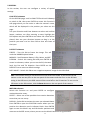
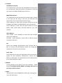
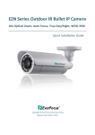
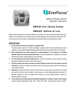
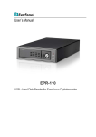
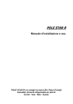
Model No. EZH5242 1080p HDcctv IP66 IR Bullet Camera User Manual Please read this manual first to ensure correct installation and operation. This manual should be retained for future reference. The information in this manual was current when published. The manufacturer reserves the right to revise and improve its products. All specifications are therefore subject to change without notice. PRECAUTIONS 1. Do not install the camera near electric or magnetic fields. Install the camera away from TV/radio transmitters, magnets, electric motors, transformers and audio speakers, because the electromagnetic fields generated by these devices may distort the video image or otherwise interfere with camera functions. 2. Never disassemble the camera beyond the recommendations in this manual, nor apply materials to it other than those recommended herein. Improper disassembly or introduction of corrosive materials may result in equipment failure or other damage. 3. Try to avoid pointing the camera toward the sun. In some circumstances, direct sunlight may cause permanent damage to the sensor and/or internal circuits. It may also create unbalanced illumination that may be beyond the camera’s ability to compensate. 4. Keep the power cable away from water and other liquids. Never touch the power cable with wet hands. Touching a wet power cable with your hands or touching the power cable with wet hands may result in electric shock. 5. Never install the camera in areas exposed to oil, gas or solvents. Oil, gas or solvents may cause equipment failure, electric shock or, in extreme cases, fire. 6. Cleaning For cameras with interchangeable lenses, do not touch the surface of the sensor directly with your hands. Use lens tissue or a cotton tipped applicator and ethanol to clean the sensor and the camera lens. Use a damp soft cloth to remove any dirt from the camera body. Do not use complex solvents, or corrosive or abrasive agents to clean any part of the camera. 7. Do not operate the camera beyond the specified temperature, humidity and power source levels. This camera is suitable for indoor and outdoor operation only. Use the camera at temperatures between -40°C~50°C (-40°F~122°F) in an IP66 complaint environment. This device is not rated as submersible. The input power source should be 12VDC or 24VAC. The use of a properly fused or “Class 2 Limited Power Source” power supply is highly recommended. 8. Mounting Select a solid mounting surface that will support the weight of the camera and any additional loading from wind, snow, ice or other factors. Securely attach the camera to the mounting surface using screws and anchors that will properly support the camera. If necessary, (e.g. when mounting the camera to a drop ceiling, or unsupported ceiling) use a safety wire to provide additional support for the camera. Federal Communication Commission Interference Statement This equipment has been tested and found to comply with the limits for a Class B digital device, pursuant to Part 15 of the FCC Rules. These limits are designed to provide reasonable protection against harmful interference in a residential installation. This equipment generates, uses and can radiate radio frequency energy and, if not installed and used in accordance with the instructions, may cause harmful interference to radio communications. However, there is no guarantee that interference will not occur in a particular installation. If this equipment does cause harmful interference to radio or television reception, which can be determined by turning the equipment off and on, the user is encouraged to try to correct the interference by one of the following measures: Reorient or relocate the receiving antenna. Increase the separation between the equipment and receiver. Connect the equipment into an outlet on a circuit different from that to which the receiver is connected. Consult the dealer or an experienced radio/TV technician for help. FCC Caution: Any changes or modifications not expressly approved by the party responsible for compliance could void the user's authority to operate this equipment. This device complies with Part 15 of the FCC Rules. Operation is subject to the following two conditions: (1) This device may not cause harmful interference, and (2) this device must accept any interference received, including interference that may cause undesired operation. ATTENTION! This is a class A product which may cause radio interference in a domestic environment; in this case, the user may be urged to take adequate measures. This Product is RoHS compliant. Your EverFocus product is designed and manufactured with high quality materials and components which can be recycled and reused. This symbol means that electrical and electronic equipment, at their end-of-life, should be disposed of separately from your household waste. WEEE Please, dispose of this equipment at your local community waste collection/recycling centre. In the European Union there are separate collection systems for used electrical and electronic product. Please, help us to conserve the environment we live in! TABLE OF CONTENTS 1. INTRODUCTION .......................................................................................................................... 1 1.1 FEATURES ......................................................................................................................................... 2 1.2 PACKAGE CONTENTS........................................................................................................................ 2 1.3 SPECIFICATIONS ............................................................................................................................... 3 2. CAMERA OVERVIEW ................................................................................................................... 5 2.1 DIMENSIONS ................................................................................................................................... 5 2.2 NAMES AND FUNCTIONS OF PARTS................................................................................................. 5 3. INSTALLATION ............................................................................................................................ 6 3.1 WIRING AND MOUNTING ............................................................................................................... 6 3.2 ADJUSTING THE CAMERA ................................................................................................................ 8 4. CAMERA SETUP ........................................................................................................................ 10 4.1 CONTROL STICK MOVEMENTS ...................................................................................................... 10 4.2 OSD OPERATION ............................................................................................................................ 11 5. CONFIGURATION WITH THE OSD............................................................................................... 12 5.1 LENS .............................................................................................................................................. 12 5.2 EXPOSURE ..................................................................................................................................... 12 5.3 WHITE BALANCE............................................................................................................................ 14 5.4 DAY & NIGHT ................................................................................................................................. 15 5.5 NR – NOISE REDUCTION ................................................................................................................ 16 5.6 SPECIAL ......................................................................................................................................... 17 5.7 ADJUST .......................................................................................................................................... 19 5.8 RESET............................................................................................................................................. 19 5.9 EXIT ............................................................................................................................................... 19 1. INTRODUCTION The EZH5242 is an HDcctv outdoor IR bullet camera with true Day/Night capability in an IP66 vandal resistant housing. Based on a 1/3” Panasonic 2.1 megapixel progressive scan sensor and 2.8~10mm varifocal megapixel lens for HD 1080p resolution 100% digital images, it delivers vastly superior video quality compared to traditional CCTV images. This superior resolution not only captures more critical evidentiary information, but the inherent ability for megapixel video also extends the area of coverage, expedites completion of investigations, resolves complaints and reduces both capital and operational costs. Designed with 44 long lifespan IR LEDs, the EZH5242 can capture images at up to 84m /275 feet in low or no light environments. This highly advanced imaging system also incorporates the following state of the art optical enhancement technologies: • EverFocus Tone Reproduction (ETR): Electronically balances lighting in challenging or unbalanced lighting conditions. • Lens Shading Compensation (LSC): Compensates to eliminate artificial shadows caused by attenuation of light as it traverses the outer portions of the lens. • EverFocus Enhanced Contrast Technology (EFECT): Dramatically improves imaging in reduced visibility conditions, cutting through smoke and fog that would blind other camera systems. • Polestar SENS-UP light low enhancement for full motion color in low light conditions without ghosting combines with EverFocus Adaptive Luminance Compensated Optimized Noise Reduction (EFALCONR) to maximize image luminance and clarity while conserving DVR disk storage space. • Digital zoom with electronic PTZ to fine tune field of view. • Image flip and rotate. No major upgrade to the IT network is required to deploy this powerful technology; HDcctv cameras communicate at digital speeds up to 1.5Gb/s over existing or new coaxial cable (RG59 or other types for longer distances), using industry standard BNC connectors. With its 3-axis positioning, varifocal 2.8~10mm megapixel auto iris lens, IP66 operation down to -40 degrees and easy mounting to a 4” electrical box, 1” conduit or directly to any flat surface the EZH5242 delivers flexible, robust coverage in a wide range of demanding surveillance environments while delivering stunning HD image quality. 1 1.1 FEATURES • • 2.1 Megapixel 1920x1080p HDcctv HD video over coax for superlative image detail 2.8~10mm AI VF megapixel lens plus optional electronic lens shading compensation captures the desired field of view with uniform image illumination • • True Day / Night operation with 44 IR LEDs for effective range up to 84 m / ~ 275 ft Provides ICR / 2D & 3D DNR / EFALCONR/SENS-UP (up to 60x) to improve picture clarity in low light scenes • ETR (EverFocus Tone Reproduction) to deliver properly exposed images despite bright light sources, deep shadows and/or unbalanced lighting in the same scene • HSBLC/BLC with programmable zones aid in control of image exposure and contrast in the presence of concentrated light sources such as automobile headlights or from deep shadows surrounding objects of interest • EFECT (EverFocus Enhanced Contrast Technology) delivers recognizable images despite interference from fog or smoke • Digital zoom increases effective lens magnification and includes PIP viewer for adjusting electronic pan, tilt and zoom • • • • • Up to 8 Privacy Zones programmable for size, location and color detection Dead pixel compensation for increased clarity and extended service life Easy to use OSD setup menu for digital signal processing feature control SD TV Out to aim and focus using a standard hand held test monitor Dual Voltage Power Source 12V DC / 24V AC • Weather Resistant IP66 rated with performance in cold climates down to -40 degrees 1.2 • • • • • • PACKAGE CONTENTS 1 x Camera Unit 1 x Speedy Mount Ring 1 x User Manual 1 x Video Test Cable 1 x Power Supply Pigtail 1 x Mounting Kit Mounting kit includes: • • • • • • • 4x 4x 4x 1x 1x 1x 1x Long Screws (for attaching Speedy Mount Ring to mounting surface) Short Screws (for connecting camera base to Speedy Mount Ring) Expanding Anchors 4 mm Hex key (for adjusting camera position) 1.5 mm Hex key (for adjusting Sunshield and set screw in base) T10 Torx key (for adjusting Lock tab and lock tab screw) Mounting Template 2 1.3 SPECIFICATIONS Pickup Device 1/3” Panasonic 2.1 megapixel Color Progressive CMOS sensor Image Pixels 1920 (H) x 1080 (V) with 2.75µ x 2.75µ pixel size HDcctv Image Area Dimensions 5.28 mm (H) x 2.97 mm (W); ø 6.06 mm area diagonal Sensitivity 0.4 lux / F=1.2; 0 lux (IR LED ON) S/N Ratio Max. 50dB Video Format Main Output HDcctv Video Resolution NTSC 30 fps at 1920 x 1080p PAL 25 fps at 1920 x 1080p Main Output Connector BNC Video Format Test Output NTSC / PAL selectable Test Output Connector Pin header; adapter cable to BNC supplied Lens Type DC Iris Megapixel Varifocal lens, f=2.8mm~10mm IR LEDs 44 LEDs with wavelength of 850nm IR Range Up to 84m / 275 feet (depends on scene IR reflectivity) True Day/Night Control Yes (Auto IR cut filter removal) OSD Menu Yes (controlled from 5-axis joystick control) Electronic Shutter Auto / Manual selectable Wide Diagonal: 94.5° Horizontal: 86.6° Vertical: 55.9° Narrow Diagonal: 33.7° Horizontal: 29.6° Vertical: 16.9° Angle of View ETR (EverFocus Tone Reproduction) Off / Low / Medium / High [Electronic Wide Dynamic Range] Lens Shading Compensation Off / On Back Light Compensation (HSBLC=Highlight Suppression Back Light Compensation) Off / BLC / HSBLC BLC (select areas from 8 x 15 grid) HSBLC (4 zones programmable for size and location) Auto Gain Control Low / Middle / High Auto White Balance ATW / Push / Manual / Outdoor / Indoor DNR Common Level Adjust 0~100 2D DNR – Off / On; 3D DNR – Off / On EFALCONR [EverFocus Adaptive Luminance Compensated Optimized Noise Reduction] – Off / On 3 EFECT (EverFocus Enhanced Contrast Technology) Low / Middle / High EFECT improves contrast in smoke, fog and similar conditions] Digital Zoom 2X~64X with optional PIP mode for ease of electronic pan / tilt alignment Motion Identification On screen highlighting of changing areas OSD Text Color Control Custom camera title; ability to change text display color and turn black text outline off / on to contrast with scene Image Flip Off/H Flip/V Flip/HV Flip (rotate 180°) Programmable Privacy Zones 8 areas independently adjustable for size, location, color OSD Text Language Selection English, Traditional Chinese , Simple Chinese, Japanese Dead Pixel Compensation Dynamic Method Off / On / Auto; Static Method Off / On; separate adjustable threshold levels Polestar SENS-UP Low light boost 2X~60X (recommended no more than 8X without careful consideration of application conditions) Power Source & Consumption DC12V 650mA 7.8W (Max) AC24V 430mA 10W (Max) Dimensions (In line) 359.9mm/14.17“ (L) x Φ105.5mm/Φ4.15“ Diameter (W) (Right angle) 312.7mm/12.3“(L) x 145mm/5.7“(H) x Φ105.5mm/Φ4.15“ Diameter (W) Weight 1.5 kg / 3.31 lbs Mounting Speedy-mount ring attaches easily to mounting surface and fits 4” electrical box pattern; camera base attaches to ring or can be removed to fit 1” conduit thread. Operating Environment -40°C~50°C / -40°F~122°F Weather Resistant IP66 rated Certifications FCC / CE 4 2. CAMERA OVERVIEW 2.1 DIMENSIONS 2.2 NAMES AND FUNCTIONS OF PARTS Front cover Speedy-mount ring Sunshield & sunshield screw Unscrew the front cover of the camera housing to reach the control stick and the lens adjustments. Lock tab & lock tab screw Lens Adjustments Focus lever (FAR-NEAR) Zoom lever (WIDE –TELE) Control Stick Power Reset button 5 Before unscrew the front cover, please, remove the sunshield and the lock tab. 3. INSTALLATION Steps: 1. Wire and mount the camera. See 3.1 2. Adjust the camera position. See 3.2 Warning To prevent electrical shock, turn off the electrical power before making electrical connections. 3.1 WIRING AND MOUNTING 1. Use the template and an appropriate tool to drill 4 holes to attach the Speedy-mount ring. (Note: If the wires from the camera will be routed on the surface, use a pliers or other suitable tool to grasp the filler closing the surface wire slot and twist to remove the filler to open the wire slot. If the wires will be routed through the rear of the camera leave the surface wire slot filler in place.) 2. Push the plastic anchors into the 4 holes. 3. Place the Speedy-mount ring against the anchoring surface so that the holes line up. Insert the four long screws and tighten them firmly. 6 4. If you don’t plan to run the cables along the surface of the wall or anchoring surface, drill a 1” hole for the camera’s two cables in the middle of the circular area “inside” of the Speedy-mount ring. Pull the cables to be connected to power & video cables from the ceiling or wall. Video & Power cables BNC Power Socket 5. Feed the two main cables through the 1” hole. Attach the camera to the Speedy-mount ring with the 4 short screws provided. 6. Connect the power, test cable, video cables from the Camera to power, handheld monitor and HDcctv DVR. 7 3.2 ADJUSTING THE CAMERA Adjust the viewing angle to the desired direction. With this 3-axis positioning system, installers can capture images from virtually any angle. The camera can be adjusted around these 3 axes: 1st axis Use a hexagon key to loosen this screw to rotate the camera 360° around its long axis. 2nd axis Use a hexagon key to loosen this screw to rotate the camera 90° around this joint. 3rd axis Twist the base carefully counterclockwise until it unscrews from the lock ring to be able to rotate the camera 360° around this axis. Once the camera is in position, turn the lock ring clockwise until it locks against the base to fix the camera in position. Tighten the set screw on the ring to fully secure the position. 8 Install the Sunshield To install or remove the sunshield, use the hexagon wrench provided to loosen the screw securing the sunshield. Slide the rib on the inside of the sunshield into the rail on the outside of the camera body – from front to back. Tighten this sunshield screw Note: When properly installed, the rear of the sunshield should be even with the rear of the camera body. If you extend the sunshield to ‘shade’ the lens, the shield could compromise image quality. 9 4. CAMERA SETUP The control stick This camera utilizes an On Screen Display (OSD) user setup menu that can be navigated by a control stick marked by (3 ) in the photo on the right) that is located next to the lens at the front of the camera housing. To access Twist the front cover Remove the Lock tab this control stick, (1) carefully and the Sunshield loosen the screws and remove the Sunshield and the Lock tab. (2) Twist the front cover carefully counterclockwise until the front cover unscrews from the camera housing. 4.1 CONTROL STICK MOVEMENTS To configure options on the OSD setup menu, move the control stick to do the actions described below. ① ENTER / CONFIRM Press this button (by pressing straight down on the stick) to display the OSD’s main menu on the monitor that you have connected directly or indirectly to the camera’s video connector. Also press this button to confirm changes and to open the submenus when they’re available and selected. (Menu items with a “<┘” symbol at the end contain submenus. For adjusting submenu items, select the desired menu item with the and buttons and press the ENTER button to open the desired submenu. Use the and buttons to toggle between value options.) ② SCROLL RIGHT Press this button (by pressing the control stick to the right) to move the on-screen cursor to the right to select items or to adjust the level/intensity of a selected function. The level/intensity increases when this button is pressed. ③ SCROLL LEFT Press this button (by pressing the control stick to the left) to move the cursor to the left to select items or to adjust the level/intensity of a selected function. The level/intensity decreases when this button is pressed. 10 ④ SCROLL DOWN Press this button (by pressing the control stick in the “down” direction) to scroll the on-screen cursor downwards between menu items. ⑤ SCROLL UP Press this button (by pressing the control stick in the “up” direction) to scroll the on-screen cursor upwards between menu items. 4.2 OSD OPERATION 1. Open the OSD menu Press the ENTER button to open the OSD’s main (“setup”) menu on your screen. 2. Scroll with the cursor buttons to select menu items Use the and buttons to move the cursor up and down to scroll to the desired menu items. 3. Toggle between the right-hand options (modes) of each menu item Use the and buttons to change the modes of menu items and to access the submenus of those modes (to adjust the parameters or values of submenu items – where applicable). Menu items with a “<┘” symbol at the end contain submenus. (If the right-hand menu title is “SET”, it means that there are no modes to choose from, only a settings submenu for the left-hand main menu item.) 4. Open submenus Right-hand items (or “modes”) with a “<┘” symbol at the end contain submenus. For adjusting submenu items, select the desired menu item with the and buttons, then select the desired submenu title (or “mode”) to the right of the menu item with the and buttons, then press ENTER to open the submenu. 5. Return to the previous page or exit the OSD quickly Scroll to RETURN and scroll between the RET and END options. If RET is selected, press ENTER to return to the previous page. If END is selected, press ENTER to exit the OSD. 6. Exit the OSD menu Scroll to EXIT and press the ENTER button to exit the OSD menu. 11 5. CONFIGURATION WITH THE OSD Once you have opened the OSD’s main menu on your screen, use the UP and DOWN buttons to scroll to the menu item of your choice. Use the LEFT and RIGHT buttons to toggle between the different modes (right-hand column) of the menu item. 5.1 LENS It is the DC mode as a factory default. 5.2 EXPOSURE Once you have opened the OSD’s main menu on your screen, use the UP and DOWN buttons to scroll to the “EXPOSURE” menu item. Press the ENTER button to open the Exposure submenu. Main menu Submenu SHUTTER Use the LEFT and RIGHT buttons to adjust the shutter speed. Choose from 1/30 ~ 1/50000, x2 ~ x60, FLK, and AUTO. Any selection other than AUTO and 1/30 will disable the SENS-UP field two lines below this field. AGC This stands for Auto Gain Control (basic low-light signal amplification). Choose from LOW ~ HIGH. The higher the AGC, the brighter the screen, but the level of noise will also increase. SENS-UP SENSE UP is used to maintain a vivid screen image by automatically boosting low light levels. Use the LEFT and RIGHT buttons to switch this function on/off and adjust its settings. Choose from OFF or AUTO. AUTO has a submenu option where you can set the SENS-UP level (x2 ~ x60). (No more than 8X SENS-UP is recommended without careful consideration of application conditions.) 12 BRIGHTNESS Scroll to this field and then scroll left or right to increase or decrease the screen brightness level (0 to 100). ETR ( EverFocus Tone Reproduction) ETR is an advanced form of electronic wide dynamic range expansion used to deliver properly exposed images despite bright light sources, deep shadows and/or unbalanced lighting in the same scene . Choose from OFF, LOW ~ HIGH. EFECT (EverFocus Enhanced Contrast Technology) EFECT analyzes the distribution of luminance across the image and processes the signal to improve contrast and increase image clarity, by reducing effects due to dispersion of light caused by fog, smoke and similar conditions. Choose from OFF, LOW ~ HIGH. BACKLIGHT • OFF • BLC (Backlight Compensation): GAIN – Select LOW ~ HIGH. Video gain is adjusted automatically to correct the exposure of subjects that are in front of a bright light source. In the AREA setting below, you can select the area on the image that this BLC Gain level will apply to. AREA – Press Enter to enter the AREA setup screen’s Position mode. Use the direction buttons to position the area selector block’s left and top borders. Press Enter again to activate the Size mode and use the direction buttons to select the area selector block’s right and bottom borders. Press Enter again to see a flashing RET and non-flashing AGAIN sign. Press Enter to return to the previous screen, or scroll right to see a non-flashing RET and a flashing AGAIN sign. Press Enter if you want to change the position of the area selector block, or scroll back to RET and press Enter to return to the previous screen (BLC). The BLC Gain setting above will apply to this area only. DEFAULT – Press Enter in this field to return the area selector block to its default position and size. • HSBLC (Highlight Suppression BLC): SELECT – Scroll sideways to select the HSBLC area selector block you want to edit. The block associated with the selected area number will start flashing when you select it. All changes in the DISPLAY field below will apply to this block only. The HSBLC Level setting (below) will only apply to the blocks that have been activated. DISPLAY – Select OFF to hide the selected area indicator block. Select ON to display the block and activate its block-positioning submenu. In ON mode, press Enter to enter the submenu and use the direction buttons to select the top and right position of the area block. Press Enter again to activate the Size mode and use the direction buttons to select the bottom and left borders of the area selector block. Press Enter again to see a flashing RET and non-flashing AGAIN sign. Press Enter to return to the previous screen, or scroll 13 right to see a non-flashing RET and a flashing AGAIN sign. Press Enter if you want to change the position of the area selector block, or scroll back to RET and press Enter to return to the previous screen (HSBLC). LEVEL – Scroll sideways to increase or decrease the HSBLC level in all the area blocks. The lower the value, the more intense the HSBLC. MODE – Choose between ALL DAY mode and NIGHT (only) mode. NIGHT mode will activate HSBLC only when light levels fall to levels associated with nighttime. BLACK MASK – Turn the black masking effect of HSBLC on or off. DEFAULT – Press Enter in this field to return all area selector blocks to their default positions and sizes. All other HSBLC settings will also return to their defaults. 5.3 WHITE BALANCE The screen color can be adjusted by using the WHITE BALANCE function. 1. Scroll to WHITE BALANCE on the main menu and use the LEFT and RIGHT buttons to toggle between this menu item’s five mode options. The modes for WHITE BALANCE are ATW, AWB, INDOOR, OUTDOOR, and MANUAL. 2. Select the desired mode and press ENTER to open the mode’s adjustment submenu, where relevant. ATW (Auto Trace White Balance) This mode can be used to view areas with a color temperature range of 1800°K to 10500°K (e.g., around fluorescent lights, outdoors, around sodium vapor lamps or inside tunnels). AWC -> SET Select this to allow the camera to automatically adjust the white balance under all conditions. Press the Enter button to “set” (adjust) the white balance automatically. INDOOR Select this mode when the color temperature of the video image is similar to that found in indoor environments (around 5100 to 5300°K). OUTDOOR Select this mode when the color temperature of the video image is similar to that found in outdoor environments (around 3,000°K to 3,200°K). MANUAL This mode enables more precise adjustments. Increase and/or decrease the Red Gain and Blue Gain values to suit the light in the surveillance area. Press Enter to access this mode’s submenu and change the Red and Blue levels. 14 5.4 DAY & NIGHT Use this menu item to select COLOR, B/W, EXTERNAL, or AUTO mode. Use the LEFT and RIGHT buttons to select the mode. Press ENTER to access the selected mode’s setting submenu, where applicable. AUTO mode switches to a B&W feed in low light conditions and then switches back to a Color feed in the daytime. The switch-over moments for this mode are triggered when the specified AGC level is reached. Press Enter to open the submenu and set the DELAY (the number of seconds that the camera will wait before switching between DAY and NIGHT modes if the threshold light level is reached – to negate temporary light changes) and the D->N (the light level at which the camera will switch from DAY mode to NIGHT mode), and the N->D (the light level at which it will switch from NIGHT to DAY mode). Note: The AGC Level must be set as middle or high in order to employ the auto switching function. B/W mode is ideal for NIGHTTIME. In this mode, the camera is forced to deliver a B&W feed during daytime and nighttime. Press Enter to access this mode’s submenu and set the BURST, IR SMART and IR LED options ON/OFF. The IR SMART option has a submenu where you can select the IR LEVEL (intensity) and AREA. IR Smart technology adjusts the IR lighting to focus on a selected area in the image and to provide just enough light to illuminate that area. The AREA submenu lets you select which area and size that would be. Select a dark part of the image, will let the whole image become brighter. 15 COLOR mode is ideal for DAYTIME. In this mode, the camera is forced to deliver a Color feed during daytime and nighttime. EXTERNAL mode switches to a B&W feed in low light conditions and then switches back to a Color feed in the daytime. It is based on the camera’s external light sensor at the front of the camera body. 5.5 NR – NOISE REDUCTION • LEAVEL as 10 performances when digital “video noise” levels are reduced. When recording digitally, the image file size can also be lessened with noise reduction. The higher the 2DNR and 3DNR settings (options are from Low to High), the more noise is filtered out. • Press Enter to access the NR submenu (2DNR and 3DNR) and select which one of the functions you want to switch ON and which ones OFF. • Select the Level of each function. • If you switch 3DNR ON, press Enter to access its submenu and set its S-Level and E-Level (see the image on the right). S-Level: Set up the AGC level to automatically start the 3D NR function. E-Level: Set up the AGC level to automatically stop the 3D NR function. • EFALCONR [EverFocus Adaptive Luminance Compensated Optimized Noise Reduction] –optimized to reduce noise in low light scenes while maximizing image luminance and clarity. Choose “OFF” or “ON”. 16 5.6 SPECIAL In this section, the user can configure a variety of special settings. CAM TITLE submenu On the SPECIAL page, scroll to CAM TITLE and scroll sideways to switch it ON, then press ENTER to access this function’s edit page where you can write or edit the camera’s name, which will be displayed in the position you select on this page. Use your Direction and Enter buttons to select and confirm letters, numbers, etc. After entering a name, highlight the POS option and press ENTER to see where the name will be placed, then use your direction buttons to drag it to the position you want it to be. Press CLR to clear one letter of the input. D-EFFECT submenu FREEZE – Turn this ON to freeze the image. This will undo the MIRROR option below. MIRROR – Scroll between Rotate, V-Flip, Mirror, and Off. D-ZOOM – Switch this setting ON and press ENTER to access its submenu, where you can set the PIP, the zoom level, the Pan and Tilt direction. Press ENTER on the DEFAULT line to return to default settings. NEG. IMAGE – Switch this ON to see a negative-exposure image of the video feed. Note: The D-Zoom setting is not functional on the SD test-out mode. If you connect an SD monitor to the test-out port on the rear panel of the camera and then turn on the D-Zoom setting in the OSD menu, the OSD menu will be turned off on the SD monitor. To turn on the OSD menu on the SD monitor, click the Reset button on the rear panel of the camera. MOTION submenu Switch this function on and press ENTER to configure motion detection zones. SELECT – Select one of the possible three motion detection zones that you can set up. DISPLAY – Select ON to activate the zone you selected above. Press ENTER to open the POSITION screen where you can position the detection zone’s indicator block. Press ENTER again to save the block’s top and left border positions and move on to the SIZE screen, where you can set the block’s bottom and right borders. 17 SENSITIVITY – Set the sensitivity of the motion detection function. MOTION VIEW – Switch this function on or off. DEFAULT – Press Enter on this field to return to the default values. PRIVACY submenu Switch this function on and press ENTER to configure privacy masks. SELECT – Select one of the possible 8 privacy zones that you can set up. DISPLAY – Select ON to activate the zone you selected above. Press ENTER to open the POSITION screen where you can position the privacy zone’s indicator block. Press ENTER again to save the block’s top and left border positions and move on to the SIZE screen, where you can set the block’s bottom and right borders. COLOR – Scroll sideways to change the selected block’s color. DEFAULT – Press Enter on this field to return to the default values. LANGUAGE Scroll sideways to select the language for the OSD. Press Enter on the selection to load that language. The OSD supports multiple languages including English, Traditional Chinese, Simplified Chinese and Japanese. DEFECT submenu Use this submenu to do Defective Pixel Correction (DPC). LIVE DPC – AUTO mode lets the camera automatically correct pixel defects, so you cannot set the Level. ON mode lets you choose the LEVEL of Live DPC in the next field. STATIC DPC – To run this function, select ON. START – Press ENTER to start the DPC actions configured above. SENS-UP – Increase or decrease the camera’s sensitivity by scrolling sideways. VERSION This line displays the Firmware Version of the camera, and can not be adjusted here. 18 5.7 ADJUST SHARPNESS submenu This submenu lets you switch the SHARPNESS function off or on, and lets you select the LEVEL of sharpness. It also lets you switch the RESOLUTION function off or on. MONITOR submenu This submenu lets you choose which monitor type is closest to the type you are using. It also lets you fine-tune the signal that is sent to the selected monitor type. Scroll sideways to select LCD and press ENTER to set the GAMMA, BLUE GAIN, and RED GAIN for your LCD monitor. Scroll sideways to select CRT and press ENTER to set the BLACK LEVEL, BLUE GAIN, and RED GAIN for your CRT monitor. OSD submenu TEXT COLOR – Scroll sideways to select the most suitable color for the OSD text. OUTLINE – Scroll sideways to switch OFF or ON the outline around the OSD text. LSC Switch Lens Shading Compensation (LSC) function ON or OFF to corrects the phenomenon where the image gets darkened or blurred on the periphery. NTSC / PAL Scroll sideways to select the applicable video transmission system for your hardware configuration. Choose 30 Hz (NTSC) or 25Hz (PAL); this also determines the video format for the SD (CVBS) test output. 5.8 RESET Pressing ENTER in this field will open the FACTORY … RESET field. IF YOU PRESS ENTER AGAIN, all settings will return to the factory default values! 5.9 EXIT Selecting EXIT will AUTOMATICALLY SAVE your settings and close the OSD screen. 19 EverFocus Electronics Corp. EverFocus Taiwan: EverFocus Europe - Germany: 12F, No.79, Sec. 1, Shin-Tai Wu Road, Hsi-Chih, Taipei, Taiwan TEL: +886 2 2698 2334 FAX: +886 2 2698 2380 www.everfocus.com.tw Albert-Einstein-Strasse 1, D-46446 Emmerich, Germany TEL: +49 2822 93940 FAX: +49 2822 939495 www.everfocus.de [email protected] [email protected] EverFocus China - Beijing: EverFocus China - Shenzhen: 4F, No. 2, D4 Building, Wan Yelong Industrial Park, Tangtou Road, Shiyan, Baoan, Shenzhen, Guangdong 518101, China TEL: +86 755 2765 1313 FAX: +86 755 2765 0337 www.everfocus.com.cn Room 609, Technology Trade Building, Shangdi Information Industry Base, Haidian District, Beijing 100085, China TEL: +86 10 6297 3336~39 FAX: +86 10 6297 1423 www.everfocus.com.cn [email protected] [email protected] EverFocus USA - California: EverFocus USA - New York: 1801 Highland Avenue, Unit A, Duarte, CA 91010, USA TEL: +1 626 844 8888 FAX: +1 626 844 8838 www.everfocus.com 415 Oser Avenue, Unit S, Hauppauge, NY 11788, USA TEL: +1 631 436 5070 FAX: +1 631 436 5027 www.everfocus.com [email protected] [email protected] EverFocus Japan: EverFocus Europe - UK: 5F, Kinshicho City Building, 2-13-4 Koto-Bashi,Sumida-Ku, Tokyo, 130-0022, Japan TEL: +81 3 5625 8188 FAX: +81 3 5625 8189 www.everfocus.co.jp Unit 12, Spitfire Business Park, Hawker Road, Croydon Surrey, CR0 4WD, UK TEL: +44 20 8649 9757 / +44 845 430 9999 FAX: +44 20 8649 9907 www.everfocusuk.co.uk [email protected] [email protected] EverFocus India: Suite 803, Housefin Bhavan, C-21, Bandra Kurla Complex, Bandra (East), Mumbai 400051, India TEL: +91 22 6128 8700 FAX: +91 22 6128 8705 www.everfocus.in [email protected] Your EverFocus product is designed and manufactured with high quality materials and components which can be recycled and reused. This symbol means that electrical and electronic equipment, at their end-of-life, should be disposed of separately from your household waste. Please, dispose of this equipment at your local community waste collection/recycling centre. In the European Union there are separate collection systems for used electrical and electronic product. Please, help us to conserve the environment we live in! Ihr EverFocus Produkt wurde entwickelt und hergestellt mit qualitativ hochwertigen Materialien und Komponenten, die recycelt und wieder verwendet werden können. Dieses Symbol bedeutet, dass elektrische und elektronische Geräte am Ende ihrer Nutzungsdauer vom Hausmüll getrennt entsorgt werden sollen. Bitte entsorgen Sie dieses Gerät bei Ihrer örtlichen kommunalen Sammelstelle oder im Recycling Centre. Helfen Sie uns bitte, die Umwelt zu erhalten, in der wir leben! P/N: 4605PZ5242B010A-Ver.B 20