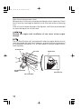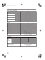
1
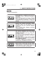
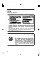
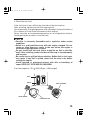
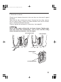
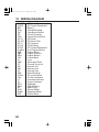
06/03/23 09:14:36 32ZT7702_006
CONTENTS
1. SAFETY INSTRUCTIONS ................................................................... 3
2. SAFETY LABEL LOCATIONS ............................................................. 6
CE mark and noise label locations .................................................... 8
3. COMPONENT IDENTIFICATION........................................................ 9
4. PRE-OPERATION CHECK ................................................................. 13
5. STARTING THE ENGINE .................................................................. 18
High altitude operation
6. GENERATOR USE ............................................................................ 25
7. STOPPING THE ENGINE .................................................................. 38
8. MAINTENANCE ................................................................................ 40
9. TRANSPORTING/STORAGE............................................................ 54
10. TROUBLESHOOTING....................................................................... 56
11. SPECIFICATIONS.............................................................................. 58
12. WIRING DIAGRAM ........................................................................... 62
13. MAJOR Honda DISTRIBUTOR ADDRESSES ................................. 68
2
06/03/23 09:14:19 32ZT7702_003
Honda
EU26i·EU30is
OWNER’S MANUAL
The‘‘e-SPEC’’mark symbolizes environmentally
responsible technologies applied to Honda power
equipment, which contains our wish to ‘‘preserve
nature for generations to come.’’
06/03/23 09:14:32 32ZT7702_005
Thank you for purchasing a Honda generator.
This manual covers operation and maintenance of the EU26i and
EU30is generators.
All information in this publication is based on the latest product
information available at the time of approval for printing.
Honda Motor Co., Ltd. reserves the right to make changes at any time
without notice and without incurring any obligation.
No part of this publication may be reproduced without written
permission.
This manual should be considered a permanent part of the generator
and should remain with it if it is resold.
Pay special attention to statements preceded by the following words:
Indicates a strong possibility of severe personal injury or
death if instructions are not followed.
Indicates a possibility of personal injury or equipment
damage if instructions are not followed.
Gives helpful information.
If a problem should arise, or if you have any questions about the
generator, consult an authorized Honda dealer.
Honda generator is designed to give safe and dependable service if
operated according to instructions. Read and understand the Owner’s
Manual before operating the generator. Failure to do so could result
in personal injury or equipment damage.
The illustration may vary according to the type.
1
06/03/23 09:14:47 32ZT7702_007
1. SAFETY INSTRUCTIONS
To ensure safe operation−
Honda generator is designed to give safe and
dependable service if operated according to
instructions.
Read and understand the Owner’s Manual
before operating the generator. Failure to do
so could result in personal injury or equipment
damage.
Exhaust gas contains poisonous carbon
monoxide. Never run the generator in an
enclosed area. Be sure to provide adequate
ventilation.
When installed inside, adequate ventilation
should be provided.
The muffler becomes very hot during
operation and remains hot for a while after
stopping the engine.
Be careful not to touch the muffler while it is
hot. Let the engine cool before storing the
generator indoors.
The engine exhaust system will be heated
during operation and remain hot immediately
after stopping the engine.
To prevent scalding, pay attention to the
warning marks attached to the generator.
Never connect a cable other than the special
cable/receptacle for parallel operation to the
parallel operation socket. Electric shocks can
result if this instruction is not followed.
3
06/03/23 09:14:59 32ZT7702_008
To ensure safe operation−
Gasoline is extremely flammable and explosive under certain
conditions. Refuel in a well ventilated area with the engine
stopped.
Keep away from cigarette, smoke and sparks when refueling
the generator. Always refuel in a well-ventilated location.
Wipe up spilled gasoline at once.
Connections for standby power to a building’s
electrical system must be made by a qualified
electrician and must comply with all
applicable laws and electrical codes. Improper
connections can allow electrical current from
the generator to back feed into the utility lines.
Such back feed may electrocute utility
company workers or others who contact the
lines during a power outage, and when utility
power is restored, the generator may explode,
burn, or cause fires in the building’s electrical
system.
4
06/03/23 09:15:07 32ZT7702_009
To ensure safe operation−
Always make a pre-operation inspection (page 13 ) before you start
the engine. You may prevent an accident or equipment damage.
Place the generator at least 1 m (3 ft) away from buildings or other
equipment during operation.
Operate the generator on a level surface.
If the generator is tilted, fuel spillage may result.
Know how to stop the generator quickly and understand operation
of all the controls. Never permit anyone to operate the generator
without proper instructions.
Keep children and pets away from the generator when it is in
operation.
Keep away from rotating parts while the generator is running.
The generator is a potential source of electrical shocks when
misused; do not operate with wet hands.
Do not operate the generator in rain or snow and do not let it get
wet.
5
06/03/23 09:15:22 32ZT7702_010
2. SAFETY LABEL LOCATIONS
These labels warn you of potential hazards that can cause serious
injury. Read the labels and safety notes and precautions described in
this manual carefully.
If a label comes off or becomes hard to read, contact your Honda
dealer for a replacement.
[For European model: G, GW, B, F types]
FUEL CAUTION/PARALLEL OPERATION CAUTION
HOT CAUTION
CONNECT
CAUTION
EXHAUST CAUTION
READ OWNER’S MANUAL
SOCKET CAUTION
6
06/03/23 09:15:31 32ZT7702_011
[For Australian model: U type]
7
06/03/23 09:15:38 32ZT7702_012
CE mark and noise label locations
[G, GW, B, F types only]
NOISE LABEL
[Example: EU30is NOISE LABEL]
CE MARK
Manufacturer and address
Maximum ambient temperature
Performance class
IP code
Maximum altitude
Dry weight
[Example: EU30is CE MARK]
8
06/03/23 09:15:43 32ZT7702_013
3. COMPONENT IDENTIFICATION
<STAND TYPE>
FRONT COVER
STARTER GRIP
FRONT HANDLE PIPE
GROUND TERMINAL
CONTROL PANEL
<WHEEL TYPE>
9
06/03/23 09:15:48 32ZT7702_014
MUFFLER
FUEL FILLER CAP
REAR HANDLE PIPE
SPARK PLUG CAP
OIL FILLER CAP
AIR CLEANER
OIL DRAIN PLUG
FRAME SERIAL NUMBER
OIL MAINTENANCE COVER
LEFT SIDE MAINTENANCE COVER
Record the frame serial number in the space below. You will need this
serial number when ordering parts.
Frame serial number:
10
06/03/23 09:15:54 32ZT7702_015
CONTROL PANEL
EU26i/EU30is: F, G, GW types
PARALLEL OPERATION SOCKET
DC CIRCUIT PROTECTOR
AC OUTPUT INDICATOR LIGHT
DC RECEPTACLE
AC OVERLOAD INDICATOR
LIGHT
OIL ALERT INDICATOR LIGHT
ENGINE SWITCH
CHOKE KNOB
FUEL VALVE LEVER
AC RECEPTACLES
ECO THROTTLE SWITCH
EU26i/EU30is: B type
AC RECEPTACLES
EU26i/EU30is: U type
AC RECEPTACLES
11
06/03/23 09:16:01 32ZT7702_016
Eco Throttle
ECO:
Engine speed is kept at idle automatically when the electrical
appliance is disconnected and it returns to the proper speed by the
electrical load when electrical appliance is connected. This position is
recommended to minimize the fuel consumption while in operation.
When high electrical load appliances is connected simultaneously,
turn the Eco Throttle switch to the OFF position to reduce voltage
changes.
Eco Throttle system does not operate sufficiently if the electrical
appliance requires the momentary electric power.
OFF:
Eco Throttle system does not operate. Engine speed is kept over rated
speed.
ECO THROTTLE SWITCH
ECO
ECO
OFF
OFF
12
06/03/23 09:16:11 32ZT7702_017
4. PRE-OPERATION CHECK
Be sure to check the generator on a level surface with the engine
stopped.
1. Check the engine oil level.
Using nondetergent oil or 2-stroke engine oil could shorten the
engine’s service life.
Use high-detergent, premium quality 4-stroke engine oil, certified to
meet or exceed U.S. automobile manufacturer’s requirements for API
Service Classification SG, SF.
Select the appropriate viscosity for the average temperature in your
area.
SAE Viscosity Grades
AMBIENT TEMPERATURE
13
06/03/23 09:16:18 32ZT7702_018
Open the oil maintenance cover.
Remove the oil filler cap, and wipe the dipstick with a clean rag. Check
the oil level by inserting the dipstick in the filler hole without screwing
it in.
If the oil level is below the end of the dipstick, refill with recommended
oil up to the top of the oil filler neck.
Running the engine with insufficient oil can cause serious engine
damage.
The Oil Alert System will automatically stop the engine before the oil
level falls below the safe limit. However, to avoid the inconvenience of
an unexpected shutdown, it is still advisable to visually inspect the oil
level regularly.
OIL FILLER CAP
DIP STICK
OIL MAINTENANCE
COVER
OIL FILLER HOLE
14
UPPER LEVEL
OIL FILLER CAP
06/03/23 09:16:28 32ZT7702_019
2. Check the fuel level.
If the fuel level is low, refill to the shoulder of the fuel strainer.
After refueling, tighten the fuel filler cap securely.
Use automotive unleaded gasoline with a Research Octane Number of
91 or higher (a Pump Octane Number of 86 or higher).
Never use stale or contaminated gasoline or an oil/gasoline mixture.
Avoid getting dirt or water in the fuel tank.
Gasoline is extremely flammable and is explosive under certain
conditions.
Refuel in a well-ventilated area with the engine stopped. Do not
smoke or allow flames or sparks in the area where the engine is
refueled or where gasoline is stored.
Do not overfill the fuel tank (there should be no fuel in the filler
neck). After refueling, make sure the fuel filler cap is closed properly
and securely.
Be careful not to spill fuel when refueling. Spilled fuel or fuel vapor
may ignite. If any fuel is spilled, make sure the area is dry before
starting the engine.
Avoid repeated or prolonged contact with skin or breathing of
vapor. KEEP OUT OF REACH OF CHILDREN.
Fuel tank capacity: 13.0 (3.43 US gal , 2.86 Imp gal)
FULL
EMPTY
FUEL STRAINER
LEVEL GAUGE
FUEL FILLER CAP
15
06/03/23 09:16:41 32ZT7702_020
Gasoline spoils very quickly depending on factors such as light
exposure, temperature and time.
In worst cases, gasoline can be contaminated within 1 month.
Using contaminated gasoline can seriously damage the engine
(carburetor clogged, valve stuck).
Such damage due to spoiled fuel is disallowed from coverage by the
warranty.
To avoid this please strictly follow these recommendations:
Only use specified gasoline (see page 15 ).
To slow deterioration, keep gasoline in a certified fuel container.
If long storage (more than 1 month) is foreseen, drain fuel tank and
carburetor.
Gasolines containing alcohol
If you decide to use a gasoline containing alcohol (gasohol), be sure it’s
octane rating is at least as high as that recommended by Honda. There
are two types of ‘‘gasohol’’: one containing ethanol, and the other
containing methanol.
Do not use gasohol that contains more than 10% ethanol. Do not use
gasoline containing methanol (methyl or wood alcohol) that does not
also contain cosolvents and corrosion inhibitors for methanol. Never
use gasoline containing more than 5% methanol, even if it has
cosolvents and corrosion inhibitors.
Fuel system damage or engine performance problems resulting
from the use of fuels that contain alcohol is not covered under the
warranty.
Honda cannot endorse the use of fuels containing methanol since
evidence of their suitability is as yet incomplete.
Before buying fuel from an unfamiliar station, try to find out if the
fuel contains alcohol, if it does, confirm the type and percentage of
alcohol used.
If you notice any undersirable operating symptoms while using a
gasoline that contains alcohol, or one that you think contains
alcohol, switch to a gasoline that you know does not contain alcohol.
16
06/03/23 09:16:49 32ZT7702_021
3. Check the air cleaner.
Check the air cleaner elements to be sure they are clean and in good
condition.
Open the left side maintenance cover. Unsnap the four clips, remove
the air cleaner cover, remove the foam element from the air cleaner
cover, and check the both elements.
Clean or replace the element(s) if necessary. (see page 42 )
Never run the engine without the air cleaner element. Rapid engine
wear will result from contaminants, such as dust and dirt, being
drawn through the carburetor, into the engine.
AIR CLEANER COVER
PAPER ELEMENT
CLIPS
FOAM ELEMENT
AIR CLEANER COVER
17
06/03/23 09:16:57 32ZT7702_022
5. STARTING THE ENGINE
Electric starting
(EU30is only)
When starting the generator after adding fuel for the first time, after
long-term storage, or after running out of fuel, turn the fuel valve
lever to the ‘‘ON’’ position, then wait for 10 to 20 seconds before
starting the engine.
Before starting the engine disconnect any load from the AC receptacle.
1. Turn the fuel valve lever to the ON position.
ON
ON
FUEL VALVE LEVER
2. Pull the choke knob out to the CLOSED position.
Do not use the choke when the engine is warm or the air temperature
is high.
CLOSED
CHOKE KNOB
18
06/03/23 09:17:05 32ZT7702_023
3. Turn the engine switch to the START position and hold it there until
the engine starts.
ON
OFF
START
OFF
ON
START
ENGINE SWITCH
Do not use the starter motor for more than 5 seconds. If the engine
fails to start, release the key, and wait at least 10 seconds before
operating the starter motor again.
When the speed of the starter motor drops after a period of time, it is
an indication that the battery should be recharged.
4. After the engine starts, let the engine switch return to the ON
position.
ON
START
ON
START
ENGINE SWITCH
19
06/03/23 09:17:08 32ZT7702_024
5. Push the choke knob to the OPEN position as the engine warms up.
OPEN
CHOKE KNOB
20
06/03/23 09:17:16 32ZT7702_025
Manual starting
When starting the generator after adding fuel for the first time, after
long-term storage, or after running out of fuel, turn the fuel valve
lever to the ‘‘ON’’ position, then wait for 10 to 20 seconds before
starting the engine.
Before starting the engine disconnect any load from the AC receptacle.
1. Turn the fuel valve lever to the ON position.
ON
ON
FUEL VALVE LEVER
2. Pull the choke knob out to the CLOSED position.
Do not use the choke when the engine is warm or the air temperature
is high.
CLOSED
CHOKE KNOB
21
06/03/23 09:17:21 32ZT7702_026
3. Turn the engine switch to the ON position.
<EU30is>
ON
OFF
OFF
ON
ENGINE SWITCH
<EU26is>
OFF
ON
OFF
ON
ENGINE SWITCH
22
06/03/23 09:17:27 32ZT7702_027
4. Pull the starter grip lightly until you feel resistance, then pull the
starter grip briskly toward the arrow as shown below.
Do not allow the starter grip to snap back. Return it slowly by hand.
Do not let the starter rope rub against the generator body or the
rope will wear out prematurely.
STARTER GRIP
5. Push the choke knob to the OPEN position as the engine warms up.
OPEN
CHOKE KNOB
23
06/03/23 09:17:33 32ZT7702_028
High altitude operation
At high altitude, the standard carburetor air-fuel mixture will be
excessively rich. Performance will decrease, and fuel consumption will
increase.
High altitude performance can be improved by specific modifications
to the carburetor. If you always operate the generator at altitudes
higher than 1,500-meter (5,000 feet) above sea level, have your
authorized Honda dealer perform these carburetor modifications.
Even with suitable carburetor jetting, engine horsepower will decrease
approximately 3.5% for each 300-meter (1,000-foot) increase in altitude.
The affect of altitude on the horse power will be greater than this if no
carburetor modification is made.
Operation of the generator at an altitude lower than the carburetor is
jetted for may result in reduced performance, overheating, and
serious engine damage caused by an excessively lean air/fuel mixture.
24
06/03/23 09:17:37 32ZT7702_029
6. GENERATOR USE
Be sure to ground the generator when the connected equipment is
grounded.
Connections for standby power to a building’s electrical system must
be made by a qualified electrician and must comply with all applicable
laws and electrical codes. Improper connections can allow electrical
current from the generator to backfeed into the utility lines. Such
backfeed may electrocute utility company workers or others who
contact the lines during a power outage, and when utility power is
restored, the generator may explode, burn, or cause fires in the
building’s electrical system.
GROUND TERMINAL
EARTH MARK
25
06/03/23 09:17:46 32ZT7702_030
Limit operation requiring maximum power (see pages 58 and 60 ) to
30 minutes.
For continuous operation, do not exceed the rated power (see
pages 58 and 60 ).
In either case, the total wattage of all appliances connected must be
considered.
Do not exceed the current limit specified for any one receptacle.
Do not connect the generator to a household circuit. This could
cause the damage to the generator or to electrical appliances in the
house.
Do not modify or use the generator for other purposes than it is
intended for. Also observe the following when using the generator.
Do not connect an extension to the exhaust pipe.
When an extension cable is required, be sure to use a tough rubber
sheathed flexible cable (IEC 245 or equivalent).
Limit length of extension cables; 60 m for cables of 1.5 mm and 100
m for cables of 2.5 mm . Long extension cables will lower usable
power due to resistance in the extension cable.
Keep the generator away from other electric cables or wires such as
commercial power supply lines.
26
06/03/23 09:17:51 32ZT7702_031
The DC receptacle can be used while the AC power is in use.
If you use both at the same time, be sure not to exceed the total
power for AC and DC. (See page 58 and 60 ).
The C type cannot be used for both AC and DC simultaneously.
Most appliance motors require more than their rated wattage for
startup.
27
06/03/23 09:17:58 32ZT7702_032
AC applications
1. Start the engine and make sure the Output indicator (green) comes
on.
2. Confirm that the appliance to be used is switched off, and plug in the
appliance.
OUTPUT INDICATOR
LIGHT (GREEN)
OVERLOAD INDICATOR
LIGHT (RED)
Substantial overloading that continuously lights the overload
indicator light (red) may damage the generator. Marginal
overloading that temporarily lights the overload indicator light (red)
may shorten the service life of the generator.
Be sure that all appliances are in good working order before
connecting them to the generator. If an appliance begins to operate
abnormally, becomes sluggish, or stops suddenly, turn off the
generator engine switch immediately. Then disconnect the
appliance, and examine it for signs of malfunction.
28
06/03/23 09:18:07 32ZT7702_033
Output and Overload Indicators
The Output indicator (green) will remain ON during normal operating
conditions.
If the generator is overloaded (see page 58 and 60 ), or if there is a
short in the connected appliance, the Output indicator (green) will go
OFF, the overload indicator (red) will go ON and current to the
connected appliance will be shut off.
Stop the engine if the Overload indicator (red) comes ON and
investigate the overload source.
The Overload indicator (red) also lights in the following cases:
When the inverter is overheated; the current to the connected
appliance will be shut off. Check to see if the air intake is obstructed.
Before connecting an appliance to the generator, check that it is in
good order, and that its electrical rating does not exceed that of the
generator. Then connect the power cord of the appliance, and start
the engine.
OUTPUT INDICATOR LIGHT
(GREEN)
OUTPUT INDICATOR LIGHT
(RED)
When an electric motor is started, both the Overload indicator (red)
and the Output indicator (green) may go on simultaneously. This is
normal if the Overload indicator (red) goes off after about five (5)
seconds. If the Overload indicator (red) stays on, consult your Honda
generator dealer.
29
06/03/23 09:18:20 32ZT7702_034
Parallel operation
Please read the item ‘‘GENERATOR USE’’ before connecting any
equipment to be used.
These are the terminals into which the special cable/receptacle is
inserted for parallel operation.
Always use only the special cable/receptacle for parallel operation.
EU26i-B, F, G, U types and EU30is-B, F, U type:
The special cable/receptacle is sold separately.
Please order the special cable/receptacle from the shop where you
purchased the unit or from a service station.
PARALLEL OPERATION SOCKET
SPECIAL CABLE/RECEPTACLE FOR
PARALLEL OPERATION
(SOLD SEPARATELY)
Limit operation requiring maximum power to 30 minutes.
For continuous operation, do not exceed the rated power.
In either case, the total wattage of all appliances connected must be
considered.
Maximum power in parallel operation is:
EU26i: 5.2 kVA
EU30is: 6.0 kVA
Rated power in parallel operation is:
EU26i: 4.8 kVA
EU30is: 5.6 kVA
30
06/03/23 09:18:31 32ZT7702_035
In parallel operation, the obtainable output differs according to the
models.
EU26i: 4.8 kVA
EU30is: 5.6 kVA
Depending on the equipment to be used, an overload may be
caused, the overload indicator light (red) may light, and it may
become impossible to take out any more electric power.
Motors generally require two to three times of their power
consumption for starting.
Never connect the different generator models and types.
Never connect a cable other than the special cable/receptacle for
parallel operation.
Connect and remove the special cable/receptacle for parallel
operation with the engine stopped.
For single operation, the special cable/receptacle for parallel
operation must be removed.
1. Hang the receptacle box of the special cable/receptacle on the front
handle pipe of unit
or unit
, and tie the longer cable of the
special cable/receptacle to the front handle pipe of the other unit
with the cable strap.
2. Connect the special cable/receptacle for parallel operation to the two
generators.
UNIT
FRONT
HANDLE
PIPE
RECEPTACLE BOX
UNIT
CABLE STRAP
SPECIAL CABLE/
RECEPTACLE FOR
PARALLEL OPERATION
31
06/03/23 09:18:39 32ZT7702_036
3. Be sure to ground the generator when the connected equipment is
grounded.
GROUND TERMINAL
4. Start each engine according to ‘‘STARTING THE ENGINE’’.
When the output indicator light (green) does not light and the
overload indicator light (red) lights instead, set the engine switch
to STOP, stop the engine once, and then start the engine again.
5. Confirm that the equipment to be used is switched off, and insert the
plug of the equipment to be used into the AC receptacle of the
receptacle box.
AC RECEPTACLE
RECEPTACLE BOX
Confirm that the use equipment to be connected is switched off.
When the equipment to be used is switched on, it will operate
suddenly, and injuries or accidents may be caused.
32
06/03/23 09:18:48 32ZT7702_037
6. Switch on the equipment to be used.
The output indicator light (green) will light.
In case of normal operation
OUTPUT INDICATOR LIGHT
(GREEN)
In case of overload operation or short-circuit
OUTPUT INDICATOR LIGHT
(RED)
In case of overload operation (refer to page 30 ) or when trouble
occurs for the equipment being used, the output indicator light
(green) will go out, the overload indicator light (red) will light
continuously, and no power will be put out.
At this time, the engine will not stop, so that the engine must be
stopped by setting the respective engine switch to STOP.
The Overload indicator (red) also lights in the following cases:
When the inverter is overheated; the current to the connected
appliance will be shut off. Check to see if the air intake is obstructed.
When equipment requiring a large starting power, like a motor etc.,
is used, the overload indicator light (red) and the output indicator
light (green) may light together for a short time (about 4 sec), but
this is no abnormality. After start of the equipment, the overload
indicator light (red) will go out and the output indicator light (green)
will stay lit.
When the operation of one generator is to be stopped after start of
the equipment, the special cable/receptacle for parallel operation
also must be removed at the same time.
7. When electric power is to be taken again from the generator, switch
off the equipment to be used and remove the plug from the AC
receptacle. Confirm that the equipment and the connection are
normal and that not too much power is to be taken, and then start
the engine.
33
06/03/23 09:18:57 32ZT7702_038
DC Application
The DC receptacle may be used for charging 12 volt automotive-type
batteries only.
DC output will vary according to the position of the EcoThrottle switch.
When the EcoThrottle switch is turned to the ON position and the AC
output is not used, the DC current will be about one-third of the rated
current.
DC Current
Eco
Eco throttle switch
OFF
Model
(do not use the AC output)
EU26i
10 A
approximately 3.3 A
EU30is
12 A
approximately 4 A
1. Connect the charging cable to the DC receptacle of the generator
and then to the battery terminals.
DC CIRCUIT PROTECTOR
(Example: EU26i)
ON
34
OFF
CHARGING CABLE
(SOLD SEPARATELY)
06/03/23 09:19:09 32ZT7702_039
To prevent the possibility of creating a spark near the battery,
connect charging cable first to the generator, then to the battery.
Disconnect cable first at the battery.
Before connecting charging cable to a battery that is installed in a
vehicle, disconnect the vehicles grounded battery cable. Reconnect
the vehicle’s grounded battery cable after the charging cables are
removed. This procedure will prevent the possibility of a short
circuit and sparks if you make accidental contact between a battery
terminal and the vehicle’s frame or body.
Do not attempt to start an automobile engine with the generator
still connected to the battery. The generator may be damaged.
Connect the positive battery terminal to the positive charging cord.
Do not reverse the charging cables, or serious damage to the
generator and/or battery may occur.
Batteries produce explosive gases: If ignited, and explosion can
cause serious injury or blindness. Provide adequate ventilation
when charging.
CHEMICAL HAZARD: Battery electrolyte contains sulfuric acid.
Contact with eyes or skin, even through plathins, may cause severe
burns. Wear a faceshield and protective clothing.
Keep flames and sparks away, and do not smoke in the area.
ANTIDOTE: If electrolyte gets into your eyes, flush thoroughly with
warm water for at least 15 minutes and call a physician
immediately.
POISON: Electrolyte is poison.
ANTIDOTE
−External: Flush thoroughly with water.
−Internal: Drink large quantities of water or milk.
Follow with milk of magnesia or vegetable oil, and call a
physician immediately.
KEEP OUT OF REACH OF CHILDREN.
35
06/03/23 09:19:14 32ZT7702_040
2. Start the engine.
The DC receptacle may be used while the AC power is in use.
An overload DC circuit will trip the DC circuit protector (push button
comes out).
If this happens, wait a few minutes before pushing in the circuit
protector to resume operation.
36
06/03/23 09:19:19 32ZT7702_041
Oil alert system
The Oil Alert system is designed to prevent engine damage caused by
an insufficient amount of oil in the crankcase. Before the oil level in the
crankcase falls below a safe limit, the Oil Alert system will
automatically shut down the engine (the engine switch will remain in
the ON position).
If the Oil Alert system shuts down the engine, the Oil Alert indicator
(red) will come on when you operate the starter, and the engine will
not run. If this occurs, add engine oil (see page 13 ).
OIL ALERT INDICATOR LIGHT (RED)
37
06/03/23 09:19:29 32ZT7702_042
7. STOPPING THE ENGINE
To stop the engine in an emergency, turn the engine switch to the OFF
position.
IN NORMAL USE:
1. Switch off the connected equipment and pull the inserted plug.
In parallel operation
2. Turn the engine switch to the OFF position.
<EU30is>
OFF
OFF
ENGINE SWITCH
<EU26i>
OFF
OFF
ENGINE SWITCH
38
06/03/23 09:19:34 32ZT7702_043
3. Turn the fuel valve lever to the OFF position.
OFF
OFF
FUEL VALVE LEVER
4. When parallel operation has been executed, remove the special
cable/receptacle for parallel operation.
SPECIAL CABLE/RECEPTACLE FOR PARALLEL
OPERATION
39
06/03/23 09:19:51 32ZT7702_044
8. MAINTENANCE
The purpose of the maintenance and adjustment schedule is to keep
the generator in the best operating condition.
Inspect or service as scheduled in the table below.
Shut off the engine before performing any maintenance. If the engine
must be run, make sure the area is well ventilated. The exhaust
contains poisonous carbon monoxide gas.
Use genuine Honda parts or their equivalent. The use of replacement
parts which are not of equivalent quality may damage the generator.
Maintenance Schedule
REGULAR SERVICE PERIOD (3)
Item
Performed at every indicated
month or operating hour interval,
whichever comes first.
Check level
Engine oil
Change
Check
Air cleaner
Clean
Replace
Clean
Sediment cup
Check-adjust
Spark plug
Replace
Check-adjust
Valve Clearance
Clean
Combustion
chamber
Clean
Fuel tank & filter
Check
Fuel line
Each use
First
month
or
20 hrs.
Every
Every
Every
year
3 months 6 months
or
or
or
100 hrs. 300 hrs.
50 hrs.
(1)
*
(2)
After every 500 hrs. (2)
(2)
Every 2 years (Replace if necessary) (2)
* Replace paper element type only.
(1)Service more frequently when used in dusty areas.
(2)These items should be serviced by your servicing dealer, unless you have the
proper tools and are mechanically proficient. Refer to Honda shop manual for
service procedures.
(3)For commercial use, log hours of operation to determine proper maintenance
intervals.
40
06/03/23 09:20:02 32ZT7702_045
1. CHANGING OIL
Drain the oil while the engine is still warm to assure rapid and
complete draining.
1. Open and remove the oil maintenance cover.
2. Remove the oil filler cap and oil drain plug to drain the oil.
3. Install the oil drain plug, and tighten it securely.
4. Refill with the recommended oil (see page 13 ) and check the oil level.
5. Reinstall, close and latch the oil maintenance cover.
ENGINE OIL CAPACITY: 0.55 (0.58 US qt , 0.48 Imp qt)
OIL DRAIN PLUG
UPPER LEVEL
OIL FILLER CAP
Wash your hands with soap and water after handling used oil.
Please dispose of used motor oil in a manner that is compatible with
the environment. We suggest you take it in a sealed container to your
local service station for reclamation. Do not throw it in the trash or
pour it on the ground.
41
06/03/23 09:20:13 32ZT7702_046
2. AIR CLEANER SERVICE
A dirty air cleaner will restrict air flow to the carburetor. To prevent
carburetor malfunction, service the air cleaner regularly. Service
more frequently when operating the generator in extremely dusty
areas.
Do not use gasoline or low flash point solvents for cleaning. They
are flammable and explosive under certain conditions.
Never run the generator without the air cleaner. Rapid engine wear
may result.
1. Open the left side maintenance cover.
2. Unsnap the clips, remove the air cleaner cover.
AIR CLEANER COVER
CLIPS
CLIPS
3. Foam element:
a. Remove the foam element from
the air cleaner cover.
b. Wash the foam element in a
solution of household detergent
and warm water, then rinse
thoroughly, or wash in
nonflammable or high
flashpoint solvent. Allow the
foam element to dry thoroughly.
FOAM ELEMENT
AIR CLEANER COVER
42
06/03/23 09:20:22 32ZT7702_047
c. Soak the foam element in clean
engine oil and squeeze out the
excess oil. The engine will smoke
during initial startup if too much
oil is left in the foam element.
d. Reinstall the foam element to the
air cleaner cover.
4. Paper element:
If the paper element is dirty, replace
it with a new one. Do not clean the
paper element.
5. Reinstall the air cleaner cover.
6. Close and latch the left side
maintenance cover.
PAPER ELEMENT
AIR CLEANER COVER
43
06/03/23 09:20:32 32ZT7702_048
3. FUEL SEDIMENT CUP SERVICE
Gasoline is extremely flammable and is explosive under certain
conditions. Do not smoke or allow flames or sparks in the area.
The filter prevents dirt or water which may be in the fuel tank from
entering the carburetor. If the engine has not been run for a long time,
the filter should be cleaned.
1. Turn the engine switch to the STOP position.
2. Turn the fuel valve lever to the OFF position.
3. Open the left side maintenance cover.
4. Remove the air cleaner cover and paper element (see page 42 and
43 ).
5. Disconnect the breather hose from the air cleaner base.
6. Remove the 6 mm bolt and two 6 mm nuts, and remove the air
cleaner base.
BREATHER HOSE
6 mm NUTS
6 mm BOLT
AIR CLEANER BASE
44
06/03/23 09:20:41 32ZT7702_049
7. Remove the sediment cup by turning it counterclockwise.
8. Clean the sediment cup, rubber gasket, and filter in nonflammable
or high flash point solvent.
9. Reassemble the filter, rubber gasket, and sediment cup. Tighten
securely.
10. Reinstall the air cleaner base, and connect the breather gas hose
with the air cleaner base.
11. Reinstall the paper element and air cleaner cover.
12. Close and latch the left side maintenance cover.
After installing the sediment cup, be sure to tighten it securely. Check
for fuel leaks and make sure the area is dry before starting the engine.
FILTER
RUBBER GASKET
SEDIMENT CUP
45
06/03/23 09:20:49 32ZT7702_050
4. SPARK PLUG SERVICE
RECOMMENDED SPARK PLUG: BPR5ES (NGK)
W16EPR-U (DENSO)
To ensure proper engine operation, the spark plug must be properly
gapped and free of deposits.
1. Open the left side maintenance cover.
2. Loosen the cover screw and remove the spark plug inspection cover.
SPARK PLUG INSPECTION COVER
COVER SCREW
3. Remove the spark plug cap.
4. Clean any dirt from around the spark plug base.
5. Use a spark plug wrench to remove the spark plug.
PLUG WRENCH
HANDLE BAR
SPARK PLUG CAP
46
06/03/23 09:20:58 32ZT7702_051
6. Visually inspect the spark plug. Discard it if the insulator is cracked
or chipped. Clean the spark plug with a wire brush if it is to be
reused.
7. Measure the plug gap with a feeler gauge.
Correct as necessary by carefully bending the side electrode.
The gap should be:
0.70−0.80 mm (0.028−0.031 in)
PLUG GAP
0.70−0.80 mm
(0.028−0.031 in)
8. Install the spark plug carefully, by hand, to avoid cross-threading.
9. After a new spark plug has been seated by hand, it should be
tightened 1/2 turn with a wrench to compress its washer.
If a used plug is being reinstalled, it should only require 1/8 to 1/4
turn after being seated.
10. Reinstall the spark plug inspection cover and tighten the cover
screw.
11. Close and latch the left side maintenance cover.
The spark plug must be securely tightened. An improperly
tightened plug can become very hot and possibly damage the
generator.
Never use a spark plug with an improper heat range.
47
06/03/23 09:21:09 32ZT7702_052
5. SPARK ARRESTER MAINTENANCE
If the generator has been running, the muffler will be very hot.
Allow it to cool before proceeding.
The spark arrester must be serviced every 100 hours to maintain its
efficiency.
1. Remove the four 6 mm cap nuts, and remove the rear cover.
2. Remove the four 6 mm bolts and the earth washer (C type only), and
remove the upper muffler protector.
6 mm BOLTS
EARTH WASHER
(C type only)
UPPER MUFFLER
PROTECTOR
6 mm CAP
NUTS
REAR COVER
3. Remove the four 8 mm bolts, and remove the rear handle pipe.
4. Remove the four 6 mm bolts and the earth washer (C type only), and
remove the rear under plate.
5. Remove the lower muffler protector.
8 mm BOLTS
LOWER MUFFLER PROTECTOR
REAR HANDLE PIPE
6 mm BOLTS
48
REAR UNDER PLATE
EARTH WASHER
(C type only)
06/03/23 09:21:15 32ZT7702_053
6. Remove the three 5 mm bolts, and remove the exhaust tail pipe and
the spark arrester.
EXHAUST TAIL PIPE
SPARK ARRESTER
5 mm BOLTS
7. Use a brush to remove carbon deposits from the spark arrester
screen.
Inspect the spark arrester screen for holes or tears. Replace if
necessary.
8. Reinstall the spark arrester and the exhaust tail pipe.
49
06/03/23 09:21:22 32ZT7702_054
9. Reinstall the lower muffler protector, the rear under plate, and the
rear handle pipe.
Reinstall the lower muffler protector inside the hook securely.
LOWER MUFFLER PROTECTOR
HOOK
LOWER
MUFFLER
PROTECTOR
HOOK
REAR HANDLE PIPE
REAR UNDER PLATE
10. Reinstall the upper muffler protector and the rear cover.
When installing the rear cover, carefully fit the rubber drip guard
around the oil filler neck and oil drain neck.
UPPER MUFFLER PROTECTOR
OIL FILLER NECK
RUBBER DRIP GUARD
OIL DRAIN NECK
50
REAR COVER
06/03/23 09:21:32 32ZT7702_055
6. FUSE REPLACEMENT
(EU30is only)
If the fuse is blown, the starter motor will not work until it is replaced.
1. Turn the engine switch to the OFF position.
2. Remove the four 6 mm cap nuts and the front cover.
FRONT COVER
6 mm CAP NUTS
3. Remove the fuse holder cover and replace the fuse.
Specified fuse: 5 A
FUSE HOLDER COVER
If frequent fuse failure occurs, determine the cause and correct the
problem before attempting to operate the generator further.
Never use a fuse with a different rating from that specified. Serious
damage to the electrical system or fire may result.
51
06/03/23 09:21:46 32ZT7702_056
7. BATTERY REMOVAL/INSTALLATION
(EU30is only)
Batteries produce explosive gases: If ignited, and explosion can
cause serious injury or blindness. Provide adequate ventilation
when charging.
CHEMICAL HAZARD: Battery electrolyte contains sulfuric acid.
Contact with eyes or skin, even through plathins, may cause severe
burns. Wear a faceshield and protective clothing.
Keep flames and sparks away, and do not smoke in the area.
ANTIDOTE: If electrolyte gets into your eyes, flush thoroughly with
warm water for at least 15 minutes and call a physician
immediately.
POISON: Electrolyte is poison.
ANTIDOTE
−External: Flush thoroughly with water.
−Internal: Drink large quantities of water or milk.
Follow with milk of magnesia or vegetable oil, and call a
physician immediately.
KEEP OUT OF REACH OF CHILDREN.
Removal:
1. Turn the engine switch to the OFF position.
2. Remove the four 6 mm cap nuts and the front cover. (see page 51 )
3. Remove the battery holder band.
4. Disconnect the battery cable at the battery negative (−) terminal,
then at the battery positive (+) terminal.
NEGATIVE (−) TERMINAL
POSITIVE (+) TERMINAL
BATTERY HOLDER BAND
5. Remove the battery from the battery tray.
52
06/03/23 09:21:52 32ZT7702_057
Installation:
1. Make sure that the engine switch is turned OFF.
2. Connect the battery positive (+) cable to the battery positive (+)
terminal, then the battery negative (−) cable to the battery negative
(−) terminal. Tighten the bolts and nuts securely.
3. Install the battery holder band.
4. Install the front cover, and install the four 6 mm cap nuts.
When disconnecting the battery cable, be sure to disconnect at the
battery negative (−) terminal first. To connect, connect at the positive
(+) terminal first, then at the negative (−) terminal. Never dis/
connect the battery cable in the reverse order, or it causes a short
circuit when a tool contacts the terminals.
53
06/03/23 09:22:04 32ZT7702_058
9. TRANSPORTING/STORAGE
To prevent fuel spillage when transporting or during temporary
storage, the generator should be secured upright in its normal
operating position, with the engine switch OFF.
The fuel valve lever should be turned OFF.
When transporting the generator:
Do not overfill the tank.
Do not operate the generator while it is on a vehicle. Take the
generator off the vehicle and use it in a well ventilated place.
Avoid a place exposed to direct sunlight when putting the
generator on a vehicle. If the generator is left in an enclosed vehicle
for many hours, high temperature inside the vehicle could cause
fuel to vaporize resulting in a possible explosion.
Do not drive on a rough road for an extended period with the
generator on board. If you must transport the generator on a rough
road, drain the fuel from the generator beforehand.
Before storing the unit for an extended period:
1. Be sure the storage area is free of excessive humidity and dust.
2. Drain the fuel.
Gasoline is extremely flammable and is explosive under certain
conditions. Perform this task in a well ventilated area with the engine
stopped. Do not smoke or allow flames or sparks in the area during
this procedure.
a. Open the left side maintenance
cover.
b. Turn fuel valve lever to ON and
then loosen the carburetor
drain screw. Drain the gasoline
from the carburetor and fuel
tank into a suitable container.
c. Tighten the carburetor drain
screw, turn the fuel valve lever
to OFF and close the left side
maintenance cover.
DRAIN SCREW
54
06/03/23 09:22:10 32ZT7702_059
3. Once a month, recharge the battery. (EU30is only)
4. Change the engine oil.
5. Remove the spark plug and pour about a tablespoon of clean engine
oil into the cylinder. Crank the engine several revolutions to
distribute the oil, then reinstall the spark plug.
6. Slowly pull the starter grip until resistance is felt. At this point, the
piston is coming up on its compression stroke and both the intake
and exhaust valves are closed. Storing the engine in this position
will help to protect it from internal corrosion.
STARTER GRIP
55
06/03/23 09:22:26 32ZT7702_060
10. TROUBLESHOOTING
When the engine will not start:
Is there fuel in
the tank?
YES
Is the engine
switch on?
YES
Is the fuel vale
lever on?
YES
Is the enough oil
in the engine?
NO
Refill the fuel
tank.
NO
Turn the engine
switch on.
NO
Turn the fuel
valve lever on.
NO
Add the
recommended
oil.
YES
Is the spark plug
in good
condition?
NO
YES
Is the fuel
reaching the
carburetor?
YES
If the engine still
does not start,
take the
generator to an
authorized
Honda dealer.
56
NO
To check:
1) Turn off the fuel valve
lever and loosen the
drain screw.
2) Turn on the fuel valve
lever. Fuel should flow
from the drain.
Clean, readjust
gap and dry the
spark plug.
Replace it if
necessary.
Clean the fuel
sediment cup.
06/03/23 09:22:37 32ZT7702_061
Appliance does not operate:
Is the Output
indicator ON?
NO
YES
Is the Overload
indicator ON?
NO
Take the
generator to an
authorized
Honda dealer.
YES
Check the
electrical
appliance or
equipment for
any defects.
NO DEFECTS
DEFECTS
Take the
generator to an
authorized
Honda dealer.
Replace the
electrical
appliance or
equipment.
Take the
electrical
appliance or
equipment to
an electrical
shop for repair.
No electricity at the DC receptacle:
Is the DC circuit
protector on?
NO
YES
Turn the DC
circuit protector
on.
Take the
generator to an
authorized
Honda dealer.
57
06/03/23 09:22:54 32ZT7702_062
11. SPECIFICATIONS
Dimensions and Weight
Model
Description code
Length
(Stand type)
(Wheel type)
Width
(Stand type)
(Wheel type)
Height
(Stand type)
(Wheel type)
Dry weight
(Stand type)
(Wheel type)
EU26i
EZGE
655 mm (25.8 in)
655 mm (25.8 in)
445 mm (17.5 in)
480 mm (18.9 in)
555 mm (21.9 in)
570 mm (22.4 in)
54 kg (119 lbs)
56 kg (123 lbs)
Engine
Model
Engine type
Displacement
Bore × Stroke
Compression ratio
Engine speed
Cooling system
Ignition system
Oil capacity
Fuel tank capacity
Spark plug
GX160
4-stroke, overhead valve, single cylinder
163 cm (9.9 cu-in)
68 × 45 mm (2.7 in × 1.8 in)
8.5:1
3,500 rpm (with eco throttle switch OFF)
Forced air
Transistorized magneto
0.55 (0.58 US qt , 0.48 Imp qt)
13.0 (3.43 US gal , 2.86 Imp gal)
BPR5ES (NGK)
W16EPR-U (DENSO)
Generator
AC
output
Model
Type
Rated Voltage (V)
Rated Frequency (Hz)
Rated Ampere (A)
Rated Output (kVA)
Max Output (kVA)
DC rated output
58
EU26i
F, G, GW, B
230
50
10.5
U
240
50
10.0
2.4
2.6
Only for charging 12 V
automotive batteries.
12 V, 10 A
06/03/23 09:23:01 32ZT7702_063
Noise
Model
Type
Sound pressure level (LpA)
According to 98/37/EC
EU26i
F, G, GW, B
75 dB
U
Microphone point
Center
CONTROL
PANEL
1.60 m
1.0 m
Guaranteed sound power level
(LWA) Tested by 2000/14/EC
90 dB
Specifications are subject to change without notice.
59
06/03/23 09:23:20 32ZT7702_064
Dimensions and Weight
Model
Description code
Length
(Stand type)
(Wheel type)
Width
(Stand type)
(Wheel type)
Height
(Stand type)
(Wheel type)
Dry weight
(Stand type)
(Wheel type)
EU30is
EZGF
655 mm (25.8 in)
655 mm (25.8 in)
445 mm (17.5 in)
480 mm (18.9 in)
555 mm (21.9 in)
570 mm (22.4 in)
59 kg (130 lbs)
61 kg (134 lbs)
Engine
Model
Engine type
Displacement
Bore × Stroke
Compression ratio
Engine speed
Cooling system
Ignition system
Oil capacity
Fuel tank capacity
Spark plug
GX200
4-stroke, overhead valve, single cylinder
196 cm (12.0 cu-in)
68 × 54 mm (2.7 in × 2.1 in)
8.5:1
3,500 rpm (with eco throttle switch OFF)
Forced air
Transistorized magneto
0.55 (0.58 US qt , 0.48 Imp qt)
13.0 (3.43 US gal , 2.86 Imp gal)
BPR5ES (NGK)
W16EPR-U (DENSO)
Generator
AC
output
Model
Type
Rated Voltage (V)
Rated Frequency (Hz)
Rated Ampere (A)
Rated Output (kVA)
Max Output (kVA)
DC rated output
60
EU30is
F, G, GW, B
230
50
12.2
U
240
50
11.7
2.8
3.0
Only for charging 12 V
automotive batteries.
12 V, 12 A
06/03/23 09:23:28 32ZT7702_065
Noise
Model
Type
Sound pressure level (LpA)
According to 98/37/EC
EU30is
F, G, GW, B
76 dB
U
Microphone point
CONTROL
PANEL
Center
1.60 m
1.0 m
Guaranteed sound power level
(LWA) Tested by 2000/14/EC
91 dB
Specifications are subject to change without notice.
61
06/03/23 09:23:32 32ZT7702_066
12. WIRING DIAGRAM
AC, NF
ACOR
BAT
Chw
CoT
CP
CPB
DC, D
DC, NF
DC, P
DC, W
DCOR
EcoSw
EgB
EgG
ESw
FrB
Fu
GeB
GT
IgC
IgU
IU
MW
OLSw
OAL
Ol
PL
REG
SeW
SP
StM
StpM
StR
62
AC Noise Filter
AC Output Receptacle
Battery
Charge Winding
Composite Socket
Circuit Protector
Control Panel Block
DC Diode
DC Noise Filter
DC Protector
DC Winding
DC Output Receptacle
Eco Throttle Switch
Engine Block
Engine Ground
Engine Switch
Frame Block
Fuse
Generator Block
Ground Terminal
Ignition Coil
Ignition Unit
Inverter Unit
Main Winding
Oil Level Switch
Oil Alert Indicator
Overload Indicator
Output Indicator
Regulator
Sub Winding
Spark Plug
Starter Motor
Stepping Motor
Starter Relay
06/03/23 09:23:38 32ZT7702_067
Bl
Y
Bu
G
R
W
Br
Lg
Gr
Lb
O
P
BLACK
YELLOW
BLUE
GREEN
RED
WHITE
BROWN
LIGHT GREEN
GRAY
LIGHT BLUE
ORANGE
PINK
ENGINE SWITCH
EU26i
IG
E
IG
E
OFF
ON
EU30is
BAT
ST
FS
G
OFF
ON
START
ECOTHROTTLE SWITCH
R/W R/Y
ON
OFF
ECOTHROTTLE
OFF
ON
63
06/03/23 09:23:51 32ZT7702_068
EU26i: G, GW, B, F
64
06/03/23 09:23:59 32ZT7702_069
EU26i: U
65
06/03/23 09:24:10 32ZT7702_070
EU30is: G, GW, B, F
66
06/03/23 09:24:24 32ZT7702_071
EU30is: U
67
06/03/23 09:24:33 32ZT7702_072
RECEPTACLE
Shape
Type
G, GW
B
F
U
68
06/03/23 09:24:58 32ZT7702_073
13. MAJOR Honda DISTRIBUTOR ADDRESSES
For European
NAME OF FIRM (COMPANY)
Honda (U.K.) Limited
Honda Europe Power Equipment S.A.
Honda Motor Europe (North) GmbH.
Honda Belgium H.V.
Honda Italia Industriale S.P.A.
Honda (Suisse) S.A.
Honda Nederland B.V.
Honda Austria G.M.B.H.
Honda Power Equipment Sweden AB
Honda Produtos De Força, Portugal, S.A.
Berema A/S
ADDRESS
470 London Road, Slough,
Berkshire, SL38QY,
TEL: FAX:
Tel: 01753-590-590
Fax: 01753-590-000
United Kingdom
Pole 45 Rue des Chataigniers
45140 Ormes
Tel: 2-38-65-06-00
Fax: 2-38-65-06-02
France
Spredlinger, Landstraße 166
D-63069 Offenbach/Main
Germany
Tel: 069-83-09-0
Fax: 069-83-09-519
Wijngaardveld 1, 9300 Aalst
Belgium
Via della Cecchignola, 5/7
00143 ROMA
Tel: 053-725-111
Fax: 053-725-100
Tel: 06-54928-1
Fax: 06-54928-400
Route des Mouliéres 10
Case postale Ch 1214
Vernier-Geneve, Switzerland
Capronilaan 1
Tel: 022-341-22-00
Fax: 022-341-09-72
1119 NN Schiphol-Rijk
Netherlands
Honda Strasse 1 A-2351
Wiener Neudorf
Fax: 020-7070001
Austria
Västkustvägen 17
202 15 Malmö,
Sweden
Tel: 020-7070000
Tel: 223-66-900
Fax: 223-66-4130
Tel: 040-600 23 00
Fax: 040-600 23 19
Lugar da Abrunheira
S. Pedro de Penaferrim
2710 Sintra, Portugal
Berghagan 5, Langhus
Tel: 351-1-9150374
Fax: 351-1-9111021
Box 454, 1401 Ski
Norway
Fax: 64-86-05-49
Tel: 64-86-05-00
69
06/03/23 09:25:23 32ZT7702_074
For European (continued)
NAME OF FIRM (COMPANY)
OY Brandt AB
TIMA PRODUCTS A/S
Greens
Automocion Canarias S.A.
(AUCASA)
The Associated Motors Company Ltd.
Two Wheels Ltd.
General Automotive Co., S.A.
BG Technik s.r.o
ADDRESS
Tuupakantie 4
SF-01740, Vantaa
TEL: FAX:
Tel: 90-895-501
Fax: 90-878-5276
Finland
Tårnfalkevej 16, Postboks 511
DK 2650 Hvidovre
Tel: 31-49-17-00
Fax: 36-77-16-30
Denmark
Polig. Industrial Congost
08530, La Garriga
(Barcelona), Spain
Tel: 93-871-84-50
Fax: 93-871-81-80
Apartado de Correos, num 206
Santa Cruz de Tenerife
Canary Island
148, Rue D’Argens, Msida
Tel: 922-61-13-50
Fax: 922-61-13-44
Malta
Crosslands Business Park,
Ballymount Road, Dublin 12,
Ireland
Fax: 356-340473
Tel: 4602111
Fax: 4566539
P.O. Box 1200, 101 73 Athens
Greece
Radlická 117/520
158 01 Praha 5
Tel: 346-5321
Fax: 346-7329
Tel: 2-5694 573
Fax: 2-5694 571
Tel: 356-333001
Czech Republic
Aries Power Equipment Ltd.
01-493 Warszawa, ul Wroclawska
25a
Poland
Tel: 22-685 17 06
Fax: 22-685 16 03
MO. TOR. PEDO Ltd.
2040 Buda-rs, Kamaraerdei-t 3.
Hungary
Tel: 23-444-971
Fax: 23-444-972
ADDRESS
1954-1956 Hume Highway
Campbelifield Victoria 3061
TEL: FAX:
Tel: (03) 9270 1111
Fax: (03) 9270 1133
For Australian
NAME OF FIRM (COMPANY)
Honda Australia Motorcycle and Power
Equipment Pty. Ltd
70