1
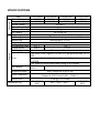
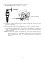
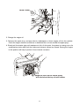
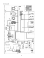
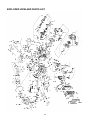
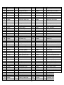
Owner’s Manual
Full Power Output Panel
SERIES GASOLINE, LPG, NG POWER
This manual provides information regarding the operation and maintenance of these
products. We have made every effort to ensure the accuracy of the information in this manual.
We reserve the right to change this product at any time without prior notice.
Please keep this manual available to all users during the entire life of the GASOLINE, LPG,
NG generator.
Engine
Generator
SPECIFICATIONS
Item
Rated Wattage
Surge Wattage
Rated Voltage
Rated Frequency
Phase
DC Output
Engine type
Ignition system
Spark Plug
Engine Speed
Compression Ratio
Displacement
Starting type
Fuel
Oil capacity
Engine oil grade
Valve Clearance
Noise Level
Dimensions (in):
PD3G4400E
3500 W
4400 W
PD3G6500E
PD3G8500E
PD3G10000E
5500 W
7000 W
8000 W
6500 W
8500 W
10000 W
120/240 V
60 Hz
Single
DC 12V/8.3 A
4-stroke OHV single cylinder with forced air cooling system
Transistorized magneto
NGK BPR6ES, F7RTC
3600 rpm
8.5 : 1
8.0 : 1
208 cc
419 cc
Electric start /Recoil
Use clean, fresh, regular LPG with LPG gas pressure area: 10~15
PSI.
Use clean, fresh, regular Natural Gas with NG gas pressure area:
0.25 PSI.
Use gasoline with a pump octane rating of 86 or higher
0.63 US qt
1.2 US qt (1.1 L)
(0.6 L)
SAE 10W30 SG or SF or SN
Intake 0.10-0.15 mm (0.004 – 0.006 in.)
Exhaust 0.15-0.20 mm (0.006 – 0.008 in.)
75 dB @ 7 m (22 feet)
28"×21.6"×
30.3"X28.7"X
30.2"×22.5"×24.2"
22.6"
25.2"
The engine exhaust from this product
contains chemicals known to the State of
California to cause cancer, birth defects
or other reproductive harm.
WARNING:
The generator is a potential source of electrical shock if misused. Do not expose the
generator to moisture, rain or snow. Do not let the generator get wet, and do not operate
it with wet hands.
Keep this owner's manual handy, so you can refer to it at any time. This owner’s manual is
considered a permanent part of the generator and should remain with the generator if resold.
Congratulations on your selection of our generator. We are certain you will be pleased with your
purchase of one of the finest generators on the market.
We want to help you get the best results from your new generator and to operate it safely. This
manual contains the information on how to do that, please read it carefully.
As you read this manual, you will find information preceded by a symbol. That information is
intended to help you avoid damage to your generator, other property, or the environment.
When your generator needs scheduled maintenance, keep in mind that our servicing dealer is
specially trained in servicing our generators. Your authorized our servicing dealer is dedicated
to your satisfaction and will be pleased to answer your questions and concerns.
A FEW WORDS ABOUT SAFETY
Your safety and the safety of others is very important. And using this generator safely is an
important responsibility.
To help you make informed decisions about safety, we have provided operating procedures
and other information on labels and in this manual. This information alerts you to potential
hazards that could hurt you or others.
Of course, it is not practical or possible to warn you about all the hazards associated with
operating or maintaining a generator. You must use your own good judgment.
You will find important safety information in a variety of forms, including;
·Safety Labels — on the generator.
·Safety Messages — Preceded by a safety alert symbol and one of three signal words,
DANGER, WARNING, or CAUTION.
These signal words mean:
DANGER: You WILL be KILLED or SERIOUSLY HURT if you don't follow instructions.
WARNING: You WILL be KILLED or SERIOUSLY HURT if you don't follow instructions.
CAUTION: You CAN be HURT if you don't follow instructions.
·Safety Headings — such as IMPORTANT SAFETY INFORMATION.
·Safety Section — such as GENERTOR SAPETY.
·Instructions — how to use this generator correctly and safely.
This entire book is filled with important safety information — please read it carefully.
CONTENTS
SAFETY ........................……………………………………………………………………........ 1
Safety Label Locations ...................... …………………………………………………..........1
Safety Information ............................ …………………………………………………………....1
COMPONENT IDENTIFICATION ......................…………………………………………………3
CONTROLS ..................…………………………………………………………………………..4
Engine Switch ................………………………………………………………………………..4
Recoil Starter ………………………………………………………....................... …….........…4
Fuel Valve Lever ……………………………………………………………………………………4
Choke Rod ..…………………………………………………………………………………..... 5
Voltage Selector Switch (Dual Voltage System) ............... ……………………….............. 5
Ground Terminal ................................................................................ ………….............. 6
DC Terminal ........................................................................................ …………..............6
DC Circuit Protector ...............……………………………………………………………………..6
Oil Alert System ................... ……………………………………………………………..........6
AC Circuit Breaker.... ………………………………………………………………………………7
AC Circuit Protector…………………………………………………………………………………8
Auto Throttle System…………………………………………………………………………………8
GENERATOR USE ................................…………………………………………………………9
Connections to a Building Electrical System..........................…………………………………9
Ground System ................................................................................... ………………………9
AC Applications .................................................................................. ………………………9
AC Operation ...................................................................................... ………………………9
AC Receptacle Selection .................................................................... ……………………… 10
DC Operation ...................................................................................... ……………………… 11
PRE-OPERATION CHECK........................... …………………………………………………12
Engine Oil ................................ …………………………………………………………………12
Fuel Recommendation ................................ …………………………………………………13
STARTING THE ENGINE/STOPPING THE ENGINE .............. ………………….................17
MAINTENANCE ................................ ……………………………………………………………19
The Importance of Maintenance ................................ ………………………………………19
Maintenance Safety ................................ ………………………………………………………20
Emission Control System Information ................................ …………………………………20
Air Index ........................................................ ………………………………………...............22
Maintenance Schedule ................................ …………………………………………………22
Engine Oil Change ................................ ………………………………………………………23
Air Cleaner Service ................................………………………………………………………23
Fuel Sediment Cup Cleaning ..............................………………………………………………24
Spark Plug Service ................................ ………………………………………………………24
Spark Arrester Maintenance................... ………………………………………………………25
TRANSPORTING/STORAGE............ ……………………………………………………………26
ASSEMBLY....…………………………………………………………………………………………28
TROUBLESHOOTING...............................…………………………………………………………29
Grounding Requirements for Power Land Portable Generators…………………………………31
WIRING DIAGRAM ................................ …………………………………………………………34
EXPLODED VIEW AND PARTS LIST....... …………………………………………………………38
SAFETY
SAFETY INFORMATION
Our generators are designed to give safe and dependable service if operated according to
instructions. Reed and understand this owner's manual before operating your generator. You
can help prevent accidents by being familiar with your generator's controls, and by observing
safe operating procedures.
Operator Responsibility
·Know how to stop the generator quickly in case of emergency.
·Understand the use of all generator controls, output receptacles, and connections.
·Be sure that anyone who operates the generator receives proper instruction. Do not let
children operate the generator without parental supervision.
Carbon Monoxide Hazards
·Exhaust contains poisonous carbon monoxide, a colorless and odorless gas. Breathing
exhaust can cause loss of consciousness and may lead to death.
·If you run the generator in an area that is confined, or even partially enclosed, the air you
breathe could contain a dangerous amount of exhaust gas. To keep exhaust gas from
building up, provide adequate ventilation.
Electric Shock Hazards
·The generator produces enough electric power to cause a serious shock or electrocution if
misused.
·Using a generator or electrical appliance in wet conditions, such as rain or snow, or near a
pool or sprinkler system, or when your hands are wet, could result in electrocution. Keep the
generator dry.
·If the generator is stored outdoors, unprotected from the weather, check all electrical
components on the control panel, before each use. Moisture or ice can cause a malfunction
or short circuit in electrical components which could result in electrocution.
·Do not connect to a building's electrical system unless an isolation switch has been installed
by a qualified electrician.
1
Fire and Burn Hazards
·The exhaust system gets hot enough to ignite some materials.
— Keep the generator at least 1 meter (3 feet) away from buildings and other equipment
during operation.
— Do not enclose the generator in any structure.
— Keep flammable materials away from the generator.
·The muffler becomes very hot during operation and remains hot for a while after stopping the
engine. Be careful not to touch the muffler while it is hot. Let the engine cool before storing
the generator indoors.
·Gasoline is extremely flammable and is explosive under certain conditions. Do not smoke or
allow flames or sparks where the generator is refueled or where gasoline is stored. Refuel in
a well-ventilated area with the engine stopped.
·Fuel vapors are extremely flammable and may ignite after the engine has started. Make sure
that any spilled fuel has been wiped up before starting the generator.
·Always keep fuel away from sparks, open flames, pilot lights, heat and other sources of
ignition.
· DO NOT light or smoke cigarettes.
WARNING: When use the LPG generator, if find any problems(LPG leakage or strange
smells), please turn off the gas source immediately and then check the connection
hose to insure the safely.
WARNING: 1. When using the LPG/Gasoline generator, please be sure that there is at least 5
feet distance between LGP tank connecting hose and the generator, to prevent
unnecessary danger because of high temperature surface of LGP tank.
2. When using the unit, please check the surface temperature of LPG tank.
3. Don't place the LPG tank in one place where ambient temperature above 35℃
and use LPG for electricity generating.
2
COMPONENT IDENTIFICATION
Record the engine and frame serial
numbers for your future reference. Refer
to these serial numbers when ordering
parts, and when making technical or
warranty inquiries.
3
CONTROLS
Engine Switch
To start and stop the engine
Switch position:
OFF:
To stop the engine. Key can be removed/inserted.
ON:
To run the engine after starting.
START: To start the engine by operating the starter motor.
OFF
OFF
ON
START
ENGINE SWITCH
ENGINE SW ITCH
ON
ON
OFF
OFF
Recoil Starter
Turn engine switch to “ON”
To start the engine, pull the starter grip lightly until
resistance is felt, then pull briskly.
NOTICE: Do not allow the starter grip to snap back
against the engine. Return it gently to
prevent damage to the starter.
The recoil starter is used to start the engine if the
generator is not equipped with a 12 volt battery to
operate the starter motor, or if the battery does not
contain adequate charge to operate the starter motor.
FUEL VALVE LEVER
Fuel Valve Lever
The fuel valve is located
between the fuel tank and
carburetor. When the fuel
valve lever is in the ON
position, fuel is allowed to flow
from the fuel tank to the
carburetor. Be sure to return
the fuel lever to the OFF
position after stopping the
engine.
FUEL VALVE LEVER
OFF
OFF
ON
ON
4
Choke Rod
The choke is used to provide an enriched fuel mixture when starting a cold engine. It can be
opened and closed by operating the choke lever manually. Move the choke lever or pull the
choke rod out to the CLOSED position to enrich the mixture for cold starting.
Voltage Selector Switch
The voltage selector switches the main power carrying windings of the generator to produce
"120V ONLY" or "120/240V". If a 240V appliance is connected to the 4-prong receptacle, the
switch must be in the "120/240V" position. If only a 120V appliance is being connected to any
of the 120V 3-prong receptacles, select the "120V ONLY" position.
120/240V:
The 120V and 120/240V receptacles can be used simultaneously. 120V
Receptacles only can output half of the rated power.
120V ONLY:
ONLY the 120V receptacles can be used. Do not use the 120/240V receptacle
in this position. Rated power will be available at the 120V twist lock receptacle.
The most power will be available at the 30A 120V locking plug receptacle.
WARNING:Change the Voltage Selector Switch after turning the AC circuit
breaker to OFF. The generator may be damaged.
5
120/240V
120V ONLY
Before using the ground
terminal, consult a qualified
electrician,
electrical
inspector or local agency
having jurisdiction for local
codes or ordinances that
apply to the intended use of
the generator.
120V ONLY
120/240V
DC Terminals
VOLTAGE SELECTOR SWITCH
The DC terminals may ONLY
be used for charging 12 volt automotive type batteries.
GROUND TERMINAL
The terminals are colored, red will identify the positive (+) terminal and black will identify the
negative (-) terminal. The battery must be connected to the generator DC terminals with the
proper polarity (battery positive must be connected to the generator red terminal and battery
negative must be connected to the generator black terminal).
DC CIRCUIT
PROTECTOR
ON
DC CIRCUIT
PROTECTOR
ON
OFF
OFF
NEGATIVE TERMINAL
(BLACK)
NEGATIVE TERMINAL
(BLACK)
POSITIVE TERMINAL
(RED)
POSITIVE TERMINAL
(RED)
DC Circuit Protector
The DC circuit protector automatically shuts off the DC battery charging circuit when the DC
charging circuit is overloaded, when there is a problem with the battery, or when the connections
between the battery and the generator are improper.
Oil Alert System
The Oil Alert System is designed to prevent engine damage caused by an insufficient of oil in
the crankcase. Before the oil level in the crankcase can fall below a safety limit, the oil alert
system will automatically stop the engine (the engine switch will remain in the ON position). If
the engine stops and will not restart, check the engine oil level before troubleshooting in other
areas.
6
Auto Throttle System
The auto throttle system automatically reduces engine speed when all loads (i.e.: tools and
appliances) are turned off or disconnected. When loads are turned on or reconnected, the
engine returns to the rated speed.
Switch Position
ON:
Recommended to minimize fuel consumption and further reduce noise levels when no
load is applied to the generator. The auto throttle system does not operate.
OFF: Recommended to minimize warm-up time when the generator is started and starting load
with large start-up power equipments.
*NOTICE: If connect to a residence, it is recommended that the auto throttle be kept in the
“ON” position if less than 50% load is being used. If the generator will be running over
50% it is recommended that you switch to the “OFF” position.
AUTO THROTTLE SWITCH
ON
OFF
AC Circuit Breaker
The circuit breaker must be in the “ON” position in order to start running a load, but it will
automatically switch “OFF” if there is a short circuit or a significant overload of the generator at
the receptacle. If the circuit breaker is switched OFF automatically, check that the appliance is
working properly and does not exceed the rated load capacity of the circuit before switching the
circuit breaker ON again.
*The circuit breaker may be used to switch the generator power ON or OFF.
PD3G4400E
PD3G10000E
AC CIRCUIT BREAKER
ON
OFF
7
AC Circuit Protector
PD3G8500E
The
AC
circuit
protectors
will
automatically switch OFF if there is a
short circuit or a significant overload of
the generator at the 20A 120V, 30A 120V
locking plug, or 120/240V locking plug
receptacle. If a AC circuit protector
switches OFF automatically, check that
the appliance is working properly and
does not exceed the rated load capacity
of the circuit before resetting the AC
circuit protector ON.
Gas Denser Device
To develop cold start performance of LPG/NG generator unit, the air REDUCER ASSY includes
one gas denser device lever, the detailed operation of the bottom is as below.
Choose the connector according to the gas you use:
● If you use LPG, you need to put the LPG hose to the LPG inlet, make the NG inlet screw
and seal well with the nut and turn the LPG/NG selector switch to LPG position.
● If you use NG, you need to put the NG
hose to the NG inlet, make the LPG inlet
screw and seal well with the nut and turn
the LPG/NG selector switch to the NG
position.
When start the cold LPG/NG generator unit,
open the valve of LPG tank or NG source, close
the resistance air valve handle, push the gas
denser device lever lightly, and keep 1-2
seconds, then stop, and then start the engine
normally.
CAUTION: Improper treatment or use of the
generator can damage it, shorten its
life and void your warranty
● The gas denser device lever only does
work after turning on the gas source valve, if start normally, no need pull the lever,
otherwise it will cause generator unit work abnormally;
● When push the gas denser device lever, the keeping time must not over 2 seconds,
otherwise it is not good for start; No need to push the gas denser device lever at every
start, only need to use when the first start of the cold generator unit or when need to
change Gas;
● If with abnormality, please contact us;
● Prohibit adjusting the LPG gas-pressure adjusting screw and gas flow adjusting screw.
8
GENERATOR USE
Connections to a Building Electrical System
Connections for standby power to a building electrical system must be made by a qualified
electrician. The connection must isolate the generator power from utility power, and must
comply with all applicable laws and electrical codes.
WARNING: Improper connections to a building electrical system will allow electrical current from
the generator to back feed into the utility lines. Such back feed will electrocute utility
company workers or others who contact the lines during a power outage, and the
generator may explode, burn, or cause fires when utility power is restored. Consult the
utility company or a qualified electrician.
Ground System
Generators have a system circuit that connects generator frame components to the ground
terminals in the AC output receptacles. The system circuit is not connected to the AC neutral
wire. If the generator is tested by a receptacle tester, it will show the same ground circuit
condition as for a home receptacle.
AC Applications
Before connecting an appliance or power cord to the generator:
•
Make sure that it is in good working order. Faulty appliances or power cords can become
hazardous and cause electrocution.
•
If an appliance begins to operate abnormally, operates sluggish or stops suddenly, turn it
off immediately. Disconnect the appliance, and determine whether the problem is the
appliance, or if the rated load capacity of the generator has been exceeded.
•
Make sure that the electrical rating of the tool or appliance does not exceed that of the
generator. Never exceed the maximum power rating of the generator. Power levels
between rated and maximum may be used for no more than 30 minutes
NOTICE: Substantial overloading will open the circuit breaker. Exceeding the time limit for
maximum power operation or slightly overloading the generator may not switch the
circuit breaker or circuit protector OFF, but will shorten the service life of the
generator.
Limit operation requiring maximum power to 30 minutes. For continuous operation (longer than
30 minutes), do not exceed the rated power. The total power requirements (kW) of all
appliances connected must be considered. Appliance and power tool manufacturers usually list
rating information near the model number or serial number.
AC Operation
1. Start the engine.
2. Turn the voltage selector switch to either position.
9
With the voltage selector switch in the ‘‘120/240V’’ position, you can use the 120V and
120/240V receptacles simultaneously. If you are NOT using the 120/240V receptacle, but
require more power from the 120V locking plug receptacle, then select the ‘‘120V ONLY’’
position.
3. Switch the AC circuit breaker ON.
4. Plug in the appliance.
Most motorized appliances require more than their rated power for startup.
Do not exceed the current limit specified for any one receptacle. If an overloaded circuit causes
the AC circuit breaker or AC circuit protector to switch OFF, reduce the electrical load on the
circuit, wait a few minutes and then reset the AC circuit breaker or AC circuit protector.
AC Receptacle Selection
The generator has two separate main power producing circuits. These two circuits supply equal
power to different receptacles shown when the voltage selector switch is in the 120/240V
position.
When two or more receptacles are used; to prevent overloading, dividing the load between the
two power circuits.
Example:
The chart below shows the rated load in amperes that can be connected to each receptacle to
balance the generator.
For Example, we have one model of generator whose total rated ampere draws 65 A.
Main Circuit I
Receptacles powered by
each main circuit
2, 4 and 6
Main Circuit II
1, 3 and 5
Main power circuit
Power distribution
2+4+6=32.5 A rated.
1+3+5=32.5 A rated.
The table shows the specifications when the
120/240V locking plug receptacle is used for
120V.
Receptacle 1 has a 20A load connected to it.
Receptacle 3 has a 15 A load connected to it. Both
receptacles are powered by main power circuit II.
The equation tells us that the total power draw on
circuit II is 35A. This is a substantial overload of
this circuit. To eliminate the excess power draw on
circuit II, the load from receptacle 3 should be
switched to receptacle 2. Now circuit I is powering
the 20A load (less than 32.5A) and circuit II is
powering a 15A load (less than 32.5A).
10
DC Operation
The DC terminals may ONLY be used for charging 12 volt automotive type batteries.
Connecting the battery cables:
1. Before connecting the battery charging cables to a battery that is
installed in a vehicle battery, disconnect the vehicle ground battery cable from the battery
negative (-) terminal.
WARNING: The battery gives off explosive
gases; keep sparks, flames and
cigarettes away. Provide adequate
ventilation when charging or using
DC CIRCUIT
batteries.
ON
PROTECTOR
Battery posts, terminals and related
accessories contain lead and lead
compounds. Wash hands after
handling.
OFF
2. Connect the positive (+) battery cable to
the automotive battery positive (+) terminal.
NEGATIVE TERMINAL
(BLACK)
POSITIVE TERMINAL
(RED)
3. Connect the negative (-) battery cable to
the automotive battery negative (-) terminal.
4. Make sure circuit breaker is off.
5. Start the generator.
NOTICE: Do not start the vehicle while the battery charging cable is connected and the
generator is running. The vehicle or the generator may be damaged.
An overloaded DC circuit, excessive current draw by the battery, or a wiring problem will trip the
DC circuit protector (PUSH button extends out). If this happens, wait a few minutes before
pushing in the circuit protector to resume operation. If the DC circuit protector continues to go
OFF, discontinue charging and see your authorized generator dealer.
Disconnecting the battery cables:
1. Stop the engine.
2. Disconnect the negative (-) battery cable from battery.
3. Disconnect the positive (+) battery cable from battery.
Auto Throttle System
With the switch in the ON position, engine speed is automatically reduced when ALL loads are
turned OFF or disconnected. When appliances are turned ON or reconnected, the engine
returns to rated speed. In the OFF position, the auto throttle system does not operate.
11
Appliances with large start-up power demands may
not allow the engine to reach normal operating rpm
when they are connected to the generator. Push the
auto throttle switch to the OFF position and connect
the appliance to the generator. If the engine still will
not reach normal operating speed, check that the
appliance does not exceed the rated load capacity of
the generator.
AUTO TH ROTTLE SWITCH
ON
OFF
ON
To avoid extended warm-up periods, keep the switch
OFF until the engine reaches operating temperature.
OFF
The auto throttle system is not effective for use with
appliances that require only momentary power. If the tool or appliance will be turned ON and
OFF quickly, the auto throttle switch should be in the OFF position.
PRE-OPERATION CHECK
Engine oil
NOTICE: Engine oil is major affecting engine performance and service life. Non-detergent and
2-stroke engine oils will damage the engine and are not recommended.
Check the oil level BEFORE EACH USE with the generator on a level surface with the engine
stopped.
SAE Viscosity Grades
AMBIENT TEMPERATURE
Use 4-stroke motor oil that meets or exceeds the requirements for API service classification SJ
or SG or SF or SN.
Always check the API SERVICE label on the oil container to be sure it includes the letters SJ
for SG or SF or SN.
SAE 10W-30 is recommended for general, all-temperature use. Other viscosities shown in the
chart may be used when the average temperature in your area is within the indicated range.
1. Remove the oil filler cap and wipe the dipstick clean.
2. Check the oil level by inserting the dipstick into the filler neck without screwing it in.
3. If the oil level is low, fill to the top of the oil filler neck with the recommended oil.
12
OIL FILLER HOLE
OIL FILLER CAP
UPPER LEVEL
Fill Fuel in tank
1. Check the fuel level gauge, and refill the tank if the fuel level is low.
2. Refuel carefully to avoid spilling fuel. Do not fill above the shoulder of the fuel strainer.
WARNING: Gasoline is highly flammable and explosive, and you can be burned or seriously injured
when refueling, if refueling is not done without caution.
•
Stop engine and keep heat, sparks, and flame away.
•
Only refuel outdoors.
•
Wipe up spills immediately.
•
It is important to use new clean fuel when refueling your unit for optimal
performance.
FUEL GAUGE
FUEL STRAINER SHOULDER
FUEL FILLER CAP
NOTICE: Fuel can damage paint and plastic. Be careful not to spill fuel when filling your fuel
tank. Damage caused by spilled fuel is not covered under warranty.
Use gasoline with a pump octane rating of 86 only.
This engine is certified to operate on unleaded gasoline.
Unleaded gasoline produces fewer engine and spark plug deposits and extends exhaust
system life.
13
Never use stale or contaminated gasoline or oil/gasoline mixture. Avoid getting dirt or water in
the fuel tank.
Occasionally you may hear a light "knock" or "pinging" (metallic rapping noise) while operating
under heavy loads. This is no cause for concern. If knock or pinging occurs at a steady engine
speed, under normal load, change to a lower octane rating.
If knock or pinging persists, see an authorized generator dealer.
NOTICE: Running the engine with persistent spark knock or pinging may cause engine
damage. Running the engine with persistent spark knock or pinging is misuse, and the
Distributor’s Limited Warranty does not cover parts damaged by misuse.
Oxygenated Fuels
Some conventional gasoline fuels are being blended with alcohol or an ether compound. This
gasoline fuel is collectively referred to as oxygenated fuels. To meet clean air standards, some
areas of the United States and Canada use oxygenated fuels to help reduce emissions.
If you use an oxygenated fuel, be sure it is unleaded and meets the minimum octane rating
requirement.
Before using an oxygenated fuel, try to confirm the fuel's contents.
Some states/provinces require this information to be posted on the pump.
The following are the EPA approved percentages of oxygenates
ETHANOL—(ethyl or grain alcohol) 10% by volume.
You may use gasoline containing up to 10% ethanol by volume. Gasoline
containing ethanol may be marketed under the name Gasohol.
MTBE — (methyl tertiary butyl ether) 15% by volume
You may use gasoline containing up to 15% MTBE by volume.
METHANOL — (methyl or wood alcohol) 5% by volume
You may use gasoline containing up to 5% methanol by volume as long as it also
contains co solvents and corrosion inhibitors to protect the fuel system. Gasoline
containing more than 5% methanol by volume may cause starting and/or
performance problems. It may also damage metal, rubber, and plastic parts of your
fuel system.
If you notice any undesirable operating symptoms, try another service station or switch to
another brand of gasoline.
Fuel system damage or performance problems resulting from the use of an oxygenated fuel
containing more than the percentages of oxygenated mentioned above are not covered under
warranty.
14
Connect LPG Tank
1. Connect LPG hose on LPG tank and fasten it to LPG inlet.
2. Turn the LPG/NG selector switch to LPG position.
3. Turn the LGP tank valve to "ON” position - full open.
4. Check the LPG to see if it is leaking and then verify that there are no leaks.
CAUTION: Use clean, fresh, regular LPG with LPG gas pressure area as we required
•
DO NOT mix oil with fuel.
•
DO NOT use CNG or NG.
•
Clean the area around the fuel cap.
•
Connect LPG hose on LPG tank and fasten it.
•
Turn the LGP tank valve to "ON” position - full open.
•
Attach the hose to the LPG fitting on the reducer, and then check for leaks.
•
When line starts to freeze or unit starts to run abnormally, replace LPG tank with a full
tank.
15
Connect NG Source
1. Connect NG hose to NG inlet and fasten it.
2. Turn the LPG/NG selector switch to NG position.
3. Turn the NG valve to "ON” position - full open.
4. Check the NG to see if it is leaking and then verify that there are no leaks.
CAUTION: Use clean, fresh, regular NG with NG gas pressure area as we required
•
DO NOT mix oil with fuel.
•
DO NOT use LPG, CNG or gasoline as fuel.
•
Clean the area around the fuel cap.
•
Connect NG tube on NG connecting tube and fasten it.
•
Turn the NG connecting tube valve to "ON” position - full open.
•
Check the NG to see if it is leaking and then verify that there is no leak.
16
STARTING THE ENGINE/STOPPING THE ENGINE
Starting the Engine of Gasoline
1. Make sure that the AC circuit breaker is in the OFF position. The generator may be hard to
start if a load is connected.
2. Turn gas valve to “OFF” position.
3. Turn the fuel valve lever to the “ON” position.
4. Move the choke lever to the “CLOSE” position.
5. Make sure the auto throttle switch is in the “OFF” position, or more time will be required for
the engine to warm up.
6. Turn the engine switch to the ON position.
7. Pull the starter grip lightly until resistance is felt, then pull briskly.
NOTICE: Do not allow the starter grip to snap back against the engine. Return it gently to
prevent damage to the starter or housing.
With electric starter:
· Connect the ground cables of battery to the generator rear housing.
· Turn the engine switch to the “START” position and hold it there for 5 seconds or until the
engine starts.
· When the engine starts, allow the engine switch to return to the ON position.
NOTICE: Operating the starter motor for more than 5 seconds can damage the motor. If the
engine fails to start, release the switch and wait 10 seconds before operating the
starter again.
If the speed of the starter motor drops after a period of time, it is an indication that the
battery should be recharged.
8. Move the choke lever to the OPEN position as the engine warms up.
9. If you wish to use the auto throttle system, turn the auto throttle switch to the ON position
after the engine has warmed up for 2 or 3 minutes.
NOTICE: Please don’t start the generator on more than one fuel at the same time. If this
happens, shut off all three (3) fuel sources, turn the key to the “OFF” position, and pull
the cord 5-10 times. Then restart normally on any one (1) fuel.
17
Starting the Engine of LPG/NG
1. Make certain the generator is on a flat, level surface.
2. Disconnect all electrical loads from the generator. Never start or stop the generator with
electrical devices plugged in or turned on.
3. Turn fuel valve to “OFF” position.
4. Connect LPG hose to the LPG tank, or Connect NG connecting tube to the NG source,
and then open the gas valve slowly, till it totally open (to insure no LPG/NG leakage).
5. Pull the starter cord slowly until resistance is felt and then pull rapidly.
6. If cannot start, push the gas denser device lever lightly, and keep 1-2 seconds, then stop,
and then restart the engine.
NOTICE: If the engine starts but does not run, make certain that the generator is on a flat, level
surface. The engine is equipped with a low oil sensor that will prevent the engine from
running when the oil level falls below a critical threshold.
NOTICE: If starting multiple times, with electric start or pull cord, and unit does not start, the
unit is flooded. Shut off all fuel sources, and turn key to start, activating the electric
start for 3-5 seconds. Then restart normally.
NOTICE: Please don’t start the generator on more than one fuel at the same time. If this
happens, shut off all three (3) fuel sources, turn the key to the “OFF” position, and pull
the cord 5-10 times. Then restart normally on any one (1) fuel.
Gasoline→LPG/NG
1. Turn fuel valve to “OFF” position. The fuel in the float bowel of carburetor allows engine to
run until the bowel is drained.
2. When the fuel in the float bowel of carburetor is running low, the engine will start to surge.
At the moment, switch on your alternate fuel source. If the unit runs rough, manually
accelerate the throttle, and enhance the rotational speed. After all fuel in the generator has
burnt out, it should run on your alternative fuel source of LPG or NG.
LPG/NG →Gasoline
1. Switch on your gasoline fuel valve
2. Slowly shut off your LPG or NG supply, the engine will start to surge, at that moment
completely switch off your LPG or NG supply. Unit should be running on gasoline.
18
Stopping the Engine
In an emergency:
To stop the engine in an emergency, move the engine switch to the OFF position.
In normal use:
1. Turn the AC circuit breaker to the “OFF” position. Unplug appliances from the generator
AC receptacles. Disconnect DC battery charging cables. Never start or stop the generator
with electrical devices plugged in or turned on.
2. Let the generator run at no-load for several minutes to stabilize internal temperatures of
the engine and generator.
3. Turn the gas valve or fuel valve to the “OFF” position. Let unit run until it dies on it’s own.
4. Turn the engine switch to the “OFF” position.
NOTICE: If turn off the switch of engine at first, the gas will continue to enter into the cylinder of
engine during the engine stopping time. Such condition will cause intense burning or more
gas so that it influence the restart.
MAINTENANCE
The Importance of Maintenance
Good maintenance is essential for safe, economical, and trouble-free operation. It will also help
reduce air pollution.
WARNING: Improper maintenance, or failure to correct a problem, can cause a malfunction in which
you can be seriously injured or killed. Always follow the inspection and maintenance
recommendations and schedules in this owner's manual.
To help you properly care for your generator, the following pages include a maintenance
schedule, routine inspection procedures, and simple maintenance procedures, using basic
hand tools. Other service tasks that are more difficult, or require special tools, are best handled
by professionals and are normally performed by a qualified mechanic.
The maintenance schedule applies to normal operating conditions. If you operate your
generator under severe conditions, such as sustained high-load or high-temperature operation,
or use in unusually wet or dusty conditions, consult your servicing dealer for recommendations
applicable to your individual needs and use.
Maintenance, replacement, or repairs of the emission control devices and systems may
be performed by any engine repair establishment or individual, using parts that are
"certified" to EPA standards.
19
Maintenance Safety
Some of the most important safety precautions are stated below, however, we cannot warn you
of every conceivable hazard that can arise in performing maintenance. Only you can decide
whether or not you should perform a given task.
Failure to properly follow maintenance instructions and precautions can lead to serious
injury or death.
Always follow the procedures and precautions in the owner's manual.
Safety precautions.
Make sure the engine is off before you begin any maintenance or repairs. This will eliminate
several potential hazards:
•
Carbon monoxide poisoning from engine exhaust.
•Be sure there is adequate ventilation whenever you operate the engine.
•
Burns from hot parts.
• Let the engine and exhaust system cool before touching. To avoid burn injuries.
•
Injury from moving parts.
• Do not run the engine unless instructed to do so.
•
Read the instructions before you begin, and make sure you have the tools and
skills required.
•
To reduce the possibility of fire or explosion, be careful when working around
gasoline. Use only a nonflammable solvent, not gasoline, to clean parts. Keep
cigarettes, sparks, and flames away from all fuel-related parts.
Remember that your servicing dealer knows your generator best and is fully equipped to
maintain and repair it.
To ensure the best quality and reliability, use only new, genuine parts for repair or replacement.
Emission Control System Information
Source of Emissions
The combustion process produces carbon monoxide, oxides of nitrogen, and hydrocarbons.
Control of hydrocarbons and oxides of nitrogen is very important because, under certain
conditions, they react to form photochemical smog when subjected to sunlight. Carbon
monoxide does not react in the same way, but it is toxic.
Our Utilizes lean carburetor settings and other systems to reduce the emissions of carbon
monoxide, oxides of nitrogen, and hydrocarbons.
20
The U.S. and California Clean Air Acts
EPA and California regulations require all manufacturers to furnish written instructions
describing the operation and maintenance of emission control systems.
The following instructions and procedures must be followed in order to keep the emissions from
your engine within the emission standards.
Tampering and Altering
Tampering with or altering the emission control system may increase emissions beyond the
legal limit. Among those acts that constitute tampering are:
•
Removal or alteration of any part of the intake, fuel, or exhaust systems.
•
Altering or defeating the governor linkage or speed-adjusting mechanism to cause the
engine to operate outside its design parameters.
Problems That May Affect Emissions
If you are aware of any of the following symptoms, have your engine inspected and repaired by
your servicing dealer.
•
Hard starting or stalling after starting.
•
Rough idle.
•
Misfiring or backfiring under load.
•
Afterburning (backfiring).
•
Black exhaust smoke or high fuel consumption.
Replacement Parts
The emission control systems on your engine were designed, built, and certified to conform to
EPA and California emission regulations. We recommend the use of genuine parts whenever
you have maintenance done. These original-design replacement parts are manufactured to the
same standards as the original parts, so you can be confident of their performance. The use of
replacement parts that are not of the original design and quality may impair the effectiveness of
your emission control system.
A manufacturer of an aftermarket part assumes the responsibility that the part will not adversely
affect emission performance. The manufacturer or rebuild of the part must certify that use of the
part will not result in a failure of the engine to comply with emission regulations.
Maintenance
Follow the maintenance schedule on page 22. Remember that this schedule is based on the
assumption that your machine will be used for its designed purpose. Sustained high-load or
high-temperature operation, or use in unusually wet or dusty conditions, will require
more frequent service.
21
Air Index
An Air Index Information hang tag/label is applied to engines certified to an emission durability
time period in accordance with the requirements of the California Air Resources Board.
The bar graph is intended to provide you, our customer; the ability to compare the emissions
performance of available engines. The lower the Air Index, the less pollution.
The durability description is intended to provide you with information relating to the engine's
emission durability period. The descriptive term indicates the useful-life period for the engine's
emission control system. See your Emission Control Warranty for additional information.
Descriptive Term
Moderate
Intermediate
Extended
Applicable to Emission Durability Period
50 hours (0-65 cc)
125 hours (greater than 65 cc)
125 hours (0-65 cc)
250 hours (greater than 65 cc)
300 hours (0-65 cc)
500 hours (greater than 65 cc)
The Air Index Information hang tag must remain on the generator until it is sold. Remove the
hang tag before operating the generator.
Maintenance Schedule
REGULAR SERVICE PERIOD(3)
ITEM Perform at every indicated month
or
operating
hour
interval,
whichever comes first
Check level
● Engine oil
Change
Check
● Air filter
Clean
● Sediment cup
Clean
Check-adjust
● Spark plug
Replace
● Idle speed
Check-adjust
● Valve clearance Check-adjust
Combustion
●
Clean
chamber
● Fuel tank
Clean
Check
● Fuel filter
Replace
● Fuel tube
Check
● LPG hose
Before
each
use
First
month
or
12 Hrs
Every
Every
Every
3 month 6 month
year
or
or
or
50 Hrs 100 Hrs 300 Hrs
〇
〇
〇
〇
〇(1)
〇
〇
〇
〇(2)
〇(2)
After every 500 Hrs(2)
Every years (2)
〇
〇(2)
Every 2 years (Replace if necessary) (2)
NOTICE: Emission related items.
22
(1) Service more frequently when used in dusty areas.
(2) These items should be serviced by your servicing dealer, unless the owner has the proper
tools and is mechanically proficient.
Engine Oil Change
Drain the oil while the engine is warm to assure complete and rapid draining.
1. Remove the drain plug and sealing washer, remove the oil filler cap, and drain the oil.
2. Install the drain plug and sealing washer. Tighten the plug securely.
3 Refill with the recommended oil and check the level.
UPPER LEVEL
OIL DRAIN PLUG
Wash your hands with soap and water after handling used oil.
Please dispose of used motor oil in a manner that is compatible with the environment. We
suggest you take it in a
CLIP
sealed container to your
ELEMENT
local service station or
recycling
center
for
reclamation. Do not throw
it in the trash or pour it on
the ground, or down a
drain.
Air Cleaner Service
A dirty air cleaner will
restrict air flow to the
carburetor. To prevent
carburetor
malfunction,
service the air cleaner
regularly. Service more
frequently when operating
the generator in extremely
dusty areas.
ELEMENT
AIR CLEANER COVER
CLIP
NOTICE: Never run the generator without the air cleaner. Rapid engine wear will result:
23
1. Unsnap the air cleaner cover clips, remove the air cleaner cover, and remove the element.
2. Wash the element in a solution of household detergent and warm water, then rinse
thoroughly, or wash in nonflammable or high flash point solvent. Allow the element to dry
thoroughly, before reinstalling.
3. Soak the element in clean engine oil and squeeze out the excess oil. The engine will smoke
during initial start-up if too much oil is left in the element.
4. Reinstall the air cleaner element wand the cover.
FUEL VALVE LEVER
Fuel Sediment Cup Cleaning
The sediment cup prevents dirt or water
which may be in the fuel tank from
entering the carburetor. If the engine has
not been run for a long time, the sediment
cup should be cleaned.
OFF
1. Turn the fuel valve lever to the “OFF”
position. Remove the sediment Cup,
O-ring, and filter.
2. Clean the sediment cup, O-ring, and
filter in nonflammable or high
flashpoint solvent.
3. Reinstall the filter, O-ring, and sediment
cup.
FUEL FILTER
4. Turn the fuel valve lever “ON” and
check for leaks.
O-RING
SEDIMENT CUP
Spark Plug Service
In order to service the spark plug, you will need a spark plug wrench (commercially available).
Recommended spark plugs: BPR5ES (NGK), W16EPR-U (DENSO), F7RTC
To ensure proper engine operation, the spark plug must be properly gapped and free of
deposits.
If the engine has been running, the muffler will be very hot. Be careful not to touch the muffler.
Allow muffler to cool down prior to coming into contact with muffler.
1. Remove the spark plug cap.
2. Clean any dirt from around the spark plug base.
3. Use a spark plug wrench to remove the spark plug.
4. Visually inspect the spark plug. Discard it if the insulator is cracked or chipped. Clean the
spark plug with a wire brush if it is to be reused.
5. Measure the plug gap with a feeler gauge.
24
Correct as necessary by carefully bending the side electrode.
The gap should be: 0.028-0.031 in (0.70--0.80 mm)
0.028-0.031 in
(0.70-0.80mm )
SPARK PLUG WRENCH
PLUG CAP
7. Check that the spark plug washer is in good condition, and thread the sparkplug in by hand
to prevent cross-threading.
8. After the spark plug is seated, tighten with a spark plug wrench to compress the washer.
— If installing a new spark plug, tighten 1/2 turn after the spark plug seats to compress the
washer. If reinstalling a used spark plug, tighten 1/8-1/4 turn after the spark plug seats to
compress the washer.
NOTICE: The Spark plug must be securely tightened. An improperly tightened Spark plug
can become very hot and could damage the engine. Never use spark plugs which
have an improper heat range. Use only the recommended Spark plugs or
equivalent.
25
TRANSPORTING STORAGE
When transporting the generator, turn the engine switch and the fuel valve OFF and keep the
generator level to prevent fuel spillage. Fuel vapor or spilled fuel may ignite.
WARNING: Contact with a hot engine or exhaust system can cause serious burns or
fires. Let the engine cool before transporting or storing the generator.
Take care not to drop or strike the generator when transporting. Do not place heavy objects on
the generator.
Before storing the unit for an extended period:
1. Be sure the storage area is free of excessive humidity and dust.
2. Service according to the table below:
RECOMMENDED
SERVICE
PROCEDURE
TO
PREVENT HARD STARTING
Less than 1 month
No preparation required
1 to 2 months
Fill with fresh gasoline and add gasoline stabilizer*.
Fill with fresh gasoline and add gasoline stabilizer*.
2 months to 1 year
Drain the carburetor float bowl.
Drain the fuel sediment cup.
Fill with fresh gasoline and add gasoline stabilizer*.
Drain the carburetor float bowl.
Drain the fuel sediment cup.
Remove the spark plug. Put a tablespoon of engine oil
into the cylinder. Turn the engine slowly with the pull rope
1 year or more
to distribute the oil. Reinstall the spark plug. Change the
engine oil.
After removal from storage, drain the stored gasoline into
a suitable container, and fill with fresh gasoline before
starting.
* Use gasoline stabilizer that are formulated to extend storage life.
STORAGE TIME
Storage Procedure
1. Drain the carburetor by loosening the drain screw. Drain the gasoline into a suitable
container.
WARNING: Gasoline is extremely flammable and is explosive under certain conditions.
Perform this task in a well ventilated area with the engine stopped. Do not
smoke or allow flames or sparks in the area during this procedure.
26
DRAIN SCREW
2. Change the engine oil.
3. Remove the spark plug, and pour about a tablespoon of clean engine oil into the cylinder.
Crank the engine several revolutions to distribute the oil, then reinstall the spark plug.
4. Slowly pull the starter grip until resistance is felt. At this point, the piston is coming up on its
compression stroke and both the intake and exhaust valves are closed. Storing the engine
in this position will help to protect it from internal corrosion.
Align the notch on the starter pulley
with the hole at the top of recoil starter.
27
ASSEMBLY
The Importance of Proper Assembly
Proper assembly is essential to operator safety and the reliability of the machine. Any error or
oversight made by the person assembling and servicing a unit can easily result in faulty
operation, damage to the machine, or injury to the operator.
WARNING: Improper assembly can cause an unsafe condition that can lead to serious
injury or death. Follow the procedures and precautions in the assembly
instructions carefully.
Some of the most important safety precautions are given below. However, we cannot warn you
of every conceivable hazard that can arise in performing this assembly. Only you can decide
whether or not you should perform a given task.
WARNING: Failure to properly follow instructions and precautions can cause you to be
seriously hurt or killed. Follow the procedures and precautions in this
manual carefully.
Important Safety Precautions
● Make sure you have a clear understanding of all basic shop safety practices and that
you are wearing appropriate clothing and safety equipment. When performing this
assembly, be especially careful of the following:
□ Read the instructions before you begin and be sure you have the tools and skills
required to perform the tasks safely.
● Make sure the engine is off before you begin any maintenance or repairs. This will help
eliminate several potential hazards:
□ Carbon monoxide poisoning from engine exhaust.
Be sure there is adequate ventilation whenever you run the engine.
□ Burns from hot parts.
Let the engine and exhaust system cool before touching.
□ Injury from moving parts.
Do not run the engine unless the instruction tells you to do so. Even then, keep your
hands, fingers, and clothing away. Do not run the engine when any protective guard or
shield is removed.
● To reduce the possibility of a fire or explosion, be careful when working around
gasoline or batteries. Use only a nonflammable solvent, not gasoline, to clean parts.
Keep all cigarettes, sparks, and flames away from all fuel-related parts.
Battery Negative Cables Connection
1. Route the battery negative cable under the tank.
2. Connect the battery negative cable from the battery
negative (-) terminal to the generator rear housing.
When disconnecting, disconnect at the generator rear
housing first.
WARNING: Battery posts, terminals and related
accessories contain lead and lead compounds. Wash hands after handling.
28
TROUBLESHOOTING
Problem
Engine
start
will
Cause
Engine switch is set to “off”.
Fuel valve is turned to “closed”.
Choke is open.
Engine is out of gas.
Engine
is
filled
with
not contaminated or old gas
Spark plug is dirty.
Spark plug is broken.
Engine runs but
there
is
no
electrical output
Generator
runs
but
does
not
support
all
electrical devices
connected.
Solution
Set engine switch to “on”.
Turn fuel valve to “open” position.
Close the choke
Add gas.
Change the gas on the engine.
Clean spark plug.
Replace spark plug.
Move generator to a level surface to
Generator is not on level
prevent low oil shutdown from
surface.
triggering.
Oil is low
Add or replace oil.
Set the circuit breaker to the “on”
Circuit breaker is off.
position.
If you are using an extension cord,
Bad connecting wires/cables.
try a different one.
Bad
electrical
device
Try connecting a different device.
connected to generator.
Try connecting fewer electrical loads
Generator is overloaded
to the generator.
Out of gas
Fill gas tank
Short in one of the connected Try disconnecting any faulty or
devices.
short-circuited electrical loads.
Air cleaner is dirty.
Change the Carbon-Brush
Clean or replace air cleaner.
29
Change the AVR
30
Grounding Requirements for Power Land Portable Generators
Portable generators are internal combustion engines used to generate electricity. They are
useful when temporary or remote power is needed, and are commonly used during cleanup
and recovery efforts following disasters.
Major Causes of Injuries and Fatalities
•
•
Shocks and electrocution to users from improper use.
Shocks and electrocution to utility workers from improper connection to structures, such
as residences, offices, shops and trailers.
Safe Work Practices
•
•
•
•
•
•
•
Maintain and operate portable generators in accordance with the manufacturer’s use
and safety instructions.
Never attach a portable generator directly to the electrical system of a structure (home,
office or trailer) unless the generator has a properly installed open-transition transfer
switch.
Always plug electrical appliances and tools directly into the generator, using the
appliance manufacturer’s supplied cords. Use heavy-duty extension cords that contain a
grounding conductor (3-wire flexible cord and 3-pronged cord connectors).
Proper grounding and bonding are a means to prevent shocks and electrocutions.
Use ground-fault circuit interrupters (GFCIs) as per the manufacturer’s instructions.
Do not connect a generator to a structure unless the generator has a properly installed
transfer switch.
Visually inspect the equipment before use; remove defective equipment from service;
replace defective equipment be for use.
Grounding Requirements for Portable and Vehicle-mounted Generators
Under the following conditions, that the frame of a portable generator need not be grounded
(connected to earth) and that the frame may serve as the ground (in place of the earth): unless
the unit is bonded. If your generator has a bonded neutral and ground you MUST ground the
generator to (earth ground with a copper ground rod)
Below you will find 1 illustration of a generator ground rod system.
•
•
The generator supplies only equipment mounted on the generator and/or cord-and
plug-connected equipment through receptacles mounted on the generator,
The noncurrent-carrying metal parts of equipment (such as the fuel tank, the internal
combustion engine, and the generator’s housing) are bonded to the generator frame,
and the equipment grounding conductor terminals (of the power receptacles that are a
part of [mounted on] the generator) are bonded to the generator frame, Thus, rather than
connect to a grounding electrode system, such as a driven ground rod, the generator’s
frame replaces the grounding electrode.
31
Below you will find 1 illustration of a generator ground rod system.
•
•
The generator supplies only equipment mounted on the generator and/or cord-and
plug-connected equipment through receptacles mounted on the generator,
The noncurrent-carrying metal parts of equipment (such as the fuel tank, the internal
combustion engine, and the generator’s housing) are bonded to the generator frame,
and the equipment grounding conductor terminals (of the power receptacles that are a
part of [mounted on] the generator) are bonded to the generator frame, Thus, rather than
connect to a grounding electrode system, such as a driven ground rod, the generator’s
frame replaces the grounding electrode.
If these conditions do not exist, then a grounding electrode, such as a ground rod, is required.
If the portable generator is providing electric power to a structure by connection via a transfer
switch to a structure (home, office, shop, trailer, or similar) it must be connected to a grounding
electrode system, such as a driven ground rod. The transfer switch must be approved for the
use and installed in accordance with the manufacturer’s installation instructions by a qualified
electrician.
Grounding requirements for generators connected via transfer switches are covered by Article
250 of the National Electrical Code (NEC).
Safe Work Practices for Portable Tools include:
•
•
•
Do not use underrated cords—replace them with appropriately rated cords that use
heavier gauge wires.
Never use electrical tools or appliances with frayed cords, missing grounding prongs, or
damaged or cracked housings.
Use double-insulated tools and equipment distinctively marked as such, where possible.
Verification by Testing
The integrity of the connection between the generator’s frame and the equipment grounding
terminals of power receptacles is important to the safe use of the equipment. The connection
may be confirmed via testing by a competent electrician with the correct equipment. The ohmic
resistance should measure near zero and must not be intermittent, which indicates a loose
connection.
Bonding Versus Grounding
Bonding and grounding are separate requirements for generators and other electrical
distribution systems. Grounding means the connection, or the establishment of a connection, of
an electric circuit or equipment to reference ground, which includes the generator’s frame.
Bonding is the intentional connection between the grounded circuit conductor (neutral) and the
grounding means for the generator, which includes the generator’s frame. Thus, effective
bonding of the neutral conductor to the generator’s frame is also a concern for the safe use of
the equipment. As with grounding terminal connections, proper bonding of the neutral terminal
of a power receptacle may be confirmed via testing by a competent electrician with the correct
32
equipment, and the ohmic resistance should measure near zero and must not be intermittent,
which indicates a loose connection.
How to ground Powerland generator:
1.Tools you will need: Sledgehammer, cooper wire (Show in picture 1)
picture 1
2.Wire the cooper line onto the knob on the panel as shown in picture 2
3.Wire the cooper line into the ground with the cooper pole embedded into the earth ground
shown in picture 3
picture 2
picture 3
33
WIRING DIAGRAM
PD3G4400E
34
PD3G6500E
35
PD3G8500E
36
PD3G10000E
37
EXPLODED VIEW AND PARTS LIST
38
Item
Part
Qty
71
21100
1
72
GB5787-86
73
Description
Item
Part
Qty
Description
Starter comp, recoil
121
12006
1
Stay, air cleaner
3
Flange bolt M6×8
122
12005
1
Case comp, air cleaner
12310
1
Fan, cover comp
123
12004
1
Separator, air cleaner
74
GB5787-86
13
Flange bolt M6×12
124
GB6177-86
6
Flange nut M5
75
19003
1
Shroud comp
125
12007
1
Cover comp, air cleaner
76
12302
3
Clip. Wire darkness
126
12008
2
Clip, air cleaner ware
77
12302
1
Grommet drain hole
127
12003
1
Element, air cleaner
78
21000
1
Start motor
128
12010
1
Seal, air cleaner
79
GB5789-86
2
Flange bolt M8×35
129
23003
1
Packing, insulator
80
GB6177-86
1
Flange nut M16
132
91009
1
Tube, fuel φ45×165
81
19005
1
Pulley, starter
133
12001
1
Tube, breather
82
19001
1
Fan, cooling
134
GB5789-86
4
Flange bolt M10×80
83
GB/T 99-88
1
Key
135
11250
1
Head comp, cylinder
84
81200
1
Flywheel comp
136
11217
2
Bolt head, M8×34
85
12215
2
Oil seal, 35×52×8
137
11202
1
Plug, spark
86
12200
1
Crank case assy.
138
15100
1
Camshaft assy.
87
87500
1
Amplifier
139
15002
2
Lifter, valve
88
12203
2
Bolt, drain lug
140
11208
1
Valve, IN.
89
12217
2
Washer, drain lug
141
11209
1
Valve, EX.
90
87601
1
Clip, wire
142
11216
1
Seat, valve spring
91
GB5789-86
2
Flange bolt M6×25
143
11212
1
92
21010
1
Contactor Assy.
144
11213
1
97
81102
1
Cord stop switch
145
11211
1
98
81103
1
Grommet cord
146
11206
2
Spring, valve
99
81100
1
Coil assy. ignition
147
15001
2
Rod, push
100
12216
1
Oil seal, 8×14×5
148
11241
1
Exhaust piper
101
GB/T276-94
2
Bearing (6202)
149
11240
1
Cover comp, head
102
12208
1
Shaft, governor arm
150
11243
1
103
12212
1
Pin, lock, 10mm
151
11242
1
Bolt, head cover
104
12209
1
Washer, 8.2×17×0.8
152
GB6175-86
2
Nut M8
105
GB6177-86
1
Flange nut M10
153
13200
1
Pipe comp EX.
106
12221
1
O-ring,14mm
154
13202
1
Casket (B) EX. Pipe
107
12200
1
Switch assy. oil level
155
11215
1
Plate, push rod guide
108
13200
1
Weight, balancer
156
11214
2
Bolt, pivot
109
13000
1
Crankshaft comp
157
11205
2
Arm, valve rocker
110
GB/T276-94
2
158
11204
2
Nut, Arm, valve rocker
111
12220
2
Pin, dowel, 12×20
159
11206
2
Nut, pivot adjusting
112
11219
1
Casket, cylinder head
160
GB5789-86
7
Flange bolt M8×40
113
11218
2
Bolt head, 8×10⁶
161
12100
1
Crankcase cover
114
23008
2
Packing, air cleaner
162
GB5789-86
3
Flange bolt M5×10
117
23000
1
Mixer
163
12301
1
Fan cover
118
23002
1
Packing, carburetor
164
121102
1
Cap assy. oil filler
119
23001
1
Insulator, carburetor
165
12230
1
Governor kit
Bearing (6207)
39
Retainer, EX. Valve spring
Rotator, valve
Retainer, IN. Valve spring
Washer comp head cover
120
GB6177-86
5
Flange nut M6
166
12214
1
Packing, case cover
167
12213
2
Pin, dowel, 8×12
176
17004
1
Arm, governor
168
13100
1
Ping set assy. piston
177
17003
1
Rod, governor
169
13105
2
Clip, piston pin
178
17005
1
Bolt, governor arm
170
13101
1
Piston
195
GB5787-86
1
Flange bolt M6×30
171
13104
1
Pin, piston
196
GB5787-86
1
Flange bolt M3×8
172
13106
1
Connecting rod assy.
197
GB6175-86
1
Nut M3
173
17220
1
Control assy.
198
17006
1
174
17001
1
Spring, governor
175
17002
1
Spring, throttle return
40
solenoid valve combination
41
Item Part
1
Qty Description
Item Part
Qty Description
1
Gasoline engine
41
14300
1
Fuel filler cap comp
2
15100
1
Frame comp
42
14400
1
Fuel sensor
3
15002
2
Bottom rubber A
43
GB 819-95
2
Screw M5×10
4
15003
2
Bottom rubber B
44
14410
1
Casket fuel tank
5
GB6177-86
16
Flange nut M8
45
GB5787-86
4
Flange bolt M6×22
6
32000
1
Reducer assy.
46
14022
4
Washer
7
32004
1
Intake hose
47
14005
4
Collar
8
GB5787-86
24
Bolt M6×12
48
14001
4
Cushion
9
15001
2
Rubber pad, frame
49
14004
1
Outlet pipeφ4.5×165
10
15201
2
Hand push
50
14006
2
Tube clip
11
11010
1
Earth terminal set
51
14003
1
Rubber, fuel tube
12
GB5787-86
8
Flange bolt M6×12
52
14100
1
Fuel cock
13
11070
1
Receptacles (30A)
53
32001
2
Clip
14
11073
1
Receptacles (50A)
55
GB5787-86
2
Flange bolt M8×32
15
11072
1
Receptacles (20A)
56
13010
1
Muffler stay
16
11120
2
Circuit Breaker
57
13020
1
Muffler
17
11090
1
Control panel
59
GB5789-86
10
Flange bolt M8×16
18
11110
1
LED smart meter
64
19
11050
2
Diode assay
65
11101
11105
2
1
DC output post
Voltage selection switch
20
11082
1
Engine switch
66
GB6177-86
2
Flange nut M12
21
11040
1
Boot, switch wire
67
GB97.1-85
2
Washer φ20
22
11030
1
Boot, main wire harness
68
21040
2
Wheel comp
23
11010
1
Boot, AC output wire
69
21020
2
Bracket
24
11060
1
Wire harness Assy.
70
21010
1
Axle
25
GB5787-86
5
Flange bolt M5×12
179
11096
1
Fuse(5A)
26
16004
1
Generator end cover
180
22001
1
Positive wire of battery
27
GB5789-86
4
Flange bolt M6×200
181
22002
1
Negative wire of battery
28
16003
1
Support stand
182
22005
1
Battery cover
29
GB5789-86
1
Bolt M10×1.25×290
183
22010
1
Battery
30
GB9701-85
1
Plain washerφ10
184
11070
1
Brush assy.
31
GB276-89
1
Bearing 6207-2RS
185
11080
1
Voltage regulator
32
16200
1
Rotor comp
186
15010
1
Protector frame side
33
16000
1
Stator & Rotor Assy.
187 15011
2
Frame cover
34
16005
1
Generator fan
188
15102
1
Frame comp,side
35
16101
1
Stator cover
189
21000
1
Wheel Assembly
36
16100
1
Stator Assy.
190
15012
1
Protector panel side
37
14201
1
Stripe, fuel tank
191
38
14200
1
Fuel tank
192
15013
11193
1
1
Protector Battery side
AC protector
39
14302
1
Fuel filter
193
11195
1
DC protector (10A)
40
14303
1
Packing ring
194
11071
1
Receptacles (30A)
42
Return Policy:
Our return policy gives you 30 days from the shipping date to return any product, provided it's new, unused,
and in the original packaging as received or defective.
We will only pay the return shipping if the return is a direct result of our error (you received an incorrect item,
defective item or shipping damaged product) and re-ship the correct item at no charge.
IMPORTANT: For tri fuel and NG generator all customers must check NG pressure before purchase which
has to be minimum 0.25PSI or 6" water column. If you find that at a later date you can not run the unit in your
area due to insufficient NG pressure and plumber or gas company not available to set up your unit you will
NOT be able to return the unit NO EXCEPTIONS.
IMPORTANT: All customers must check your altitude before purchasing any Powerland generator unit which
will not operate normally if the altitude is above 3000 feet. If you find that you are not able to run the unit after
receiving it due to altitude above 3000 feet and you did not check your altitude before purchase you will NOT
be able to return the unit NO EXCEPTIONS.
Factory Warranty:
Powerland items carry a 1-year limited parts warranty. If, under the course of normal operation, the
Powerland item fails within 1 year from the date of purchase as a result of faulty materials or workmanship,
Powerland will provide necessary replacement or repair parts at no charge for the parts. Labor costs are not
included under this warranty policy and are the responsibility of the buyer. This warranty does not cover
failure due to normal wear and tear or abuse. This warranty applies only to purchases made directly with
Powerland and its authorized distributors. This warranty is void with misapplication, misuse, or negligence of
the product.
Special Note: all battery in the generator will only have 3 month warranty from the date of receiving the
generator.
43