1
SNMP Application for the MINT Router
SNMP Application for the MINT Router
(Walkstation II project)
Markus Oelhafen
EURECOM Institute
June 1994
The Royal Institute of Technology
Departement of Teleinformatics / TSlab
Electrum 204
S - 164 40 KISTA
Sweden
Institut EURECOM
BP 193
F- 06904 Sophia Antipolis Cedex
FRANCE
page 1
SNMP Application for the MINT Router
SNMP Application for the MINT Router
(Walkstation II project)
Markus Oelhafen
EURECOM Institute
Ecole Nationale Supérieure des Télécommunications de
Paris
(Telecom University of Paris)
January - June 1994
Supervisors:
Prof. Gerald Q. Maguire
The Royal Institute of Technology
Departement of Teleinformatics / TSlab
Electrum 204
S - 164 40 KISTA
Sweden
Prof. Pierre Humblet
Institut EURECOM
C.I.C.A
BP 194
F-06904 SOPHIA ANTIPOLIS Cédex
page 2
SNMP Application for the MINT Router
Acknowledgements
I would like to express my gratitude to a number of people who have helped me during my work at
KTH.
Special thanks go to the head of the Teleinformatics Department of the Royal Institute of Technology
(KTH) Professor Björn Pehrson who accepted me as a thesis student in the Telcommuncation Systems
Laboratory (TSlab) group. My work at KTH was financially supported by Ellemtel Utvecklings AB.
Thanks go to this enterprise.
Much credit for this Master Thesis should go to my supervisor Professor Gerald Maguire. He answered
many questions in the context of my work with an impressive competence. Furhtermore, he helped me
to acquire a method of independant work.
Yuri Ismailov’s excellent experience in software development was of much benefit for me during my
work. I thank him for the time he took to advise me and for the many interesting discussions I had with
him.
Parag Pruthi gave me some valuable ideas for the outline of this report. I also owe him much gratitude
for his constructive corrections of parts of the report.
Many thanks to Frank Reichert for the documentation he gave me and for allowing me to include some
of his figures into the current report.
I would like to express my deep gratitude to the computer system administrators Jim Svensson and
Fredrik Ljungberg who answered my many questions and helped me to find solutions to problems concerning software development and the installation of software packages on the local computer systems.
Thanks to all the members of the Teleinformatics Department who have welcomed me into their laboratories. Many thanks for the friendly human atmosphere they created for my working environment.
page 3
SNMP Application for the MINT Router
1 Introduction
Mobile Communication is an area which has been growing steadily over the last few years. While
Mobile Telephony has already reached a high level of penetration and has been realized in large international systems, Mobile Data Networks are just developing. As computers become smaller, less
expensive, and more powerful, the user’s demand for mobility increases. People will no longer be willing to use their computers only from a fixed location(s).
Standards for Digital Mobile Telephony already exist in Europe (GSM, DECT), in the United States
(e.g., Qualcomm System) and in Japan (e.g., PHP). However, Mobile Data Communication will bring
additional requirements to these systems. In order to allow hosts to migrate without losing the benefit
of their full processing power, the bandwidth of today’s communication systems must be increased.
Furthermore, the network should be strongly interconnected with the existing (fixed) computer networks. Unfortunately, many of those have properties which inhibit mobility. They were developed at a
time, when the assumption was that all the hosts are fixed. New frameworks of mobile computers will
have to cope with these properties. These are just some of the many problems which must be resolved
to create this new generation of wireless systems. Besides supporting host migration they will allow for
data services which combine voice and video (Multimedia), the remote access to a data base via a wireless link, applications using Data Multicast, etc.
Management is without any doubt a crucially important component of such a mobile communication
system. Network Management is a broad field. An operator of a communication system may want to
monitor the system’s behaviour under any conditions. He may want to detect faults and taking measures in order to isolate and repair them. These are just a few examples of NM functions. To provide
them, an NM application needs to control all kind of objects in a communication network. Examples of
such objects are hardware components or subsystems of network devices, programs and their interaction with the environment, whole clusters of machines forming subnetworks, etc. The support for
Mobility can make the management task particularly complex. The existence of radio links brings up a
new set of specific variables which must be controlled. Furthermore, mobility implies that the system
must in some way keep track on its users, in order to provide services for them, wherever they are.
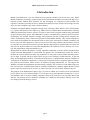
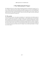
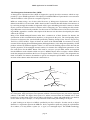
The purpose of the Walkstation II project [8] is to create a testbed for a wireless Local Area Network
(LAN) with access to the Internet (Figure 1). To the user, the system should be transparent, i.e., he or
she should be able to work on a mobile computer exactly in the same way as on any other host in the
Internet. The network services should be available in a continuous and seamless fashion, even if the
user changes location during a session.
page 4
SNMP Application for the MINT Router
basestation
G
?
INTER
NET
GHz RADIO
Infrared
...
?
LAN
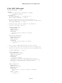
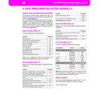
Figure 1: The system will give mobile users access to a Local Area Network (LAN) which is
connected via a Gateway (G) to the Internet. As a mobile host is typically a portable computer, the
mobility support functions will be distributed onto the Base Station and an entity which will be
associated with the mobile station.
The organisations who cooperate with the Royal Institute of Technology (KTH) in this project are Ellemtel, Ericsson Radio Systems, Hewlett Packard, NUTEK and Telia Research. At KTH there are three
groups involved: The Radio Systems (RS) Lab is in charge of developing a strategy for the allocation
of the needed radio resources. The Electronics System Design Lab has developed a new Radio Transceiver which satisfies the special requirements of the planned wireless LAN. The Telecommunication
Systems Lab has the task of defining protocols for use with personal computing and communication
systems, writing the necessary software, and assembling the different elements of the planned network.
This report is organized as follows: Chapter 2 is a short description of these elements and of the Walkstation II Project as a whole. It also states the general requirements for Network Management which
exist in this context. Chapter 3 focuses on the Network Management issues. It introduces the communication protocol which we have used and the general design of the management application. It also
shows how the concepts of the architecture are realized with the selected tools. The reader who is interested in technical details is refered to the Appendix.
page 5
SNMP Application for the MINT Router
2 The Walkstation II Project
The Walkstation II project is being conducted at the Royal Institute of Technology. Its purpose is to create a wireless LAN with access to the Internet. This chapter gives an overview on the Walkstation II
project. The first subsection shows the planned system from a global point of view. The following three
sections describe shortly its main functional blocks. These are the Mobile INTernet Router (MINT), the
Radio Transceiver, an the Mobile*IP Protocol. The last section of this chapter states the requirements
for the Network Management Application.
2.1 The system
In the Walkstation II project, the software and hardware for communication and mobility support is
located in a separate device, the MINT (implied byFigure 1). This approach has some major advantages: The MINT can be designed in a way that it is compatible with many different types of Mobile
Hosts (MH) and the operating system of the MH does not have to undergo any modifications. Furthermore the mobility does not cause additional computational load on the MH. The wireless communication devices for the mobile host and for the base station are MINTs which are identical in hardware.
The actual asymmetry is in software, in the implementation of the network layer protocol Mobile*IP
(see section 2.4). This protocol allows the user to change LANs yet still being reachable via a temporary network address.
page 6
SNMP Application for the MINT Router
Radio
MINT
MS
Mobile
Host
MS
Mobile Station
BS
LAN
Radio
GW
MINT
Base Station
Internet
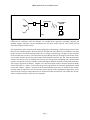
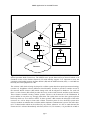
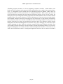
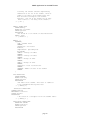
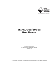
Figure 2: The main elements of the wireless LAN are the Mobile INTernet (MINT) Router and a
Spread spectrum Radio Transceiver. The MINTs run a special Network Layer Protocol which is an
extended version of the Internet Protocol (IP) with mobility support. It is important to note the
symmetric relationship between the Base Station (BS) and the Mobile Station (MS), i.e. each MS has
basically the same equipment as a BS.
The wireless LAN which is being developed is a cellular system based on spread spectrum technology
(section 2.3). Neighbour cells use different virtual channels. In order to provide a seamless access to
the network, Mobile Stations (MS) which change cells will be subjected to handover. For each cell
there is a Base Station (BS) which provides the access to the wired Network and thus to the Internet.
These features resemble existing cellular systems. However, the framework of the Walkstation II
project differs in one point very strongly from them: The system does not have the typical top down
hierarchy which we see in GSM or DECT. In these systems a BS controls the allocation of the radio
resources in a cell or keeps at least track of them. From this point of view, the KTH system more
closely resembles an ethernet than a cellular mobile telephone communication system. The radio channel is a shared media which can be utilized, by any station, whenever it is free to send ethernet like
Frames and it is released immediately after that (section 2.2). For instance, it is possible for an MS to
page 7
SNMP Application for the MINT Router
send data directly to another MS within the same cell, without utilizing the BS. The Base Station is
needed to route data packets to and from the fixed network and to and from other cells. Therefore, the
approach of the Walkstation II project is somehow a synthesis of a wireless data network which does
packet routing and the location update facilities of a cellular radio system. We will see in section 3.3
how these considerations influence the framework of the network management.
2.2 The Mobile INTernet (MINT) Router
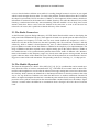
The MINT resembles a host computer (Figure 3). Besides the Central Processing Unit (CPU) it has
CPU
RAM
ROM
WLAN
IR
ETHERNET
Radio
DUAL PORT
RAM
SLIP/PPP
Serial
Network
Host (MH-MINT)
ETHERNET
Network (MH-MINT)
DUAL PORT
RAM
SCSI
Serial
Parallel
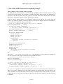
Figure 3: Basic components of a MINT
Integrated Circuits containing ROM and RAM. The MACH Kernel which was ported by Anders
Klemets at the TS Lab allows to run an emulator of the a UNIX operating system and thus UNIX software. The computational power of the MINT is roughly 10 MIPS, i.e., comparable with a SUN Microsystems SLC. It is also equipped with multiple communication interfaces. This is to provide
compatibility with many different types of hosts, as well as to connect to several types of wireless networks. The standard configuration of the MINT has two sets of communication interfaces. One of them
is dedicated to the connection with the Mobile Host (MH) if the MINT is part of a Mobile Station. It is
used to connect to the wired subnetwork if the MINT is part of a Base Station. The other set is in both
cases the interface to the wireless communication device. The MINT will have an infrared transceiver
which can work at very high bitrates (up to 10 Mbits/s), but is rather limited in coverage area, and a
spread spectrum radio transceiver which is described later in this report. For the rest of this report we
will only consider the latter device. As stated in section 2.1, the Media Access (MAC) layer protocol
for the radio channel works much like a Carrier Sense Multiple-Access system with Collision Avoidance (CSMA/CA), i.e., some what differently that the control of an Ethernet which uses Carrier Sense
Multiple-Access system with Collision Detection (CSMA/CD). It is not possible for a Radio Trans-
page 8
SNMP Application for the MINT Router
ceiver to check whether collisions occur while it is sending, though, because it recieves its own signal
which is much stronger than any other. To resolve this problem, Tomoki Oshawa from the TS Lab has
developed a system with Collision Avoidance (CSMA/CA). In his approach, all the stations, which have
information to send wait for the channel to be available, then they wait (after the channel is free), while
listening, a random time before they start transmitting. With this method it is less likely, that several
stations which have data to send, access the channel at the same time as soon as the last user has
released it. Of course, this is paid with a reduced efficiency of the channel.
2.3 The Radio Transceiver
At the Electronic Systems Design laboratory of KTH, Daniel Kerek and his team are developing the
radio part for the Walkstation II project. Their approach is based on a spread spectrum radio transceiver
which operates at a frequency of 2 GHz. One (or) more virtual channels are assigned to a cell, i.e.,
inside one cell, then all the stations use the same spreading code. We recall from section 2.2 that the
scheme by which a channel is shared between the users is called CSMA/CA. In the Walkstation II
project CDMA was rather chosen than FDMA or TDMA for the simplicity of its implementation. The
usage of FDMA would have required a more complex analog part of the radio transceiver. TDMA is
not suitable because of its synchronization problems between the traffic of different cells. Measurements with channels at this frequency range in a closed room with persons moving around, showed
typical coherence times of the channel of 20 ms. This will be important in our considerations concerning power control of the radio transmitter. The spreading codes are 13 bits long, i.e., 13 chips per bit.
2.4 The Mobile IP protocol
The Network Integration of a Mobile Host (MH) [10], [11], [13] is a problem that can be treated separately from the issues of wireless communication. E.g., if the MH moves around inside its home subnetwork (which might have several cells) the solution to message routing turns out to be trivial because
the Gateway which connects the subnetwork to the Internet will have to route the packets in the same
way as for any fixed host. Problems arise when the MH moves to another subnetwork. Because IP
makes an implicit assumption that the host’s attachment point remains fixed, currently defined routing
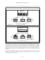
protocols select a path to a host based on the network number contained in the host’s IP address. Figure
4 shows a scenario where the MH tries to communicate from a foreign LAN with a host of its home
LAN.
page 9
SNMP Application for the MINT Router
G
INTERNET
Home LAN
G
Foreign LAN
Request
S
MH
Response
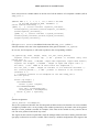
Figure 4: In this scenario a Mobile Host (MH) is attached to a foreign LAN and tries to contact a
server on his home LAN. The request will reach the server as the IP Address of the corresponding
packet allows for finding the fixed host in the Internet. On the other hand, the response message will
never reach its destination since the IP addressing scheme associates the MH’s IP Address with a
location which is on its home LAN. The Gateway G of the home LAN has no means to know where the
MH is and consequently discards the packet.
The packets are routed correctly towards the host on the Home LAN. The inverse is not possible, as the
MH’s traditional IP address implies that it is located on his home LAN. In the Walkstation II project,
the Mobil*IP protocol [13] [14] which is described hereafter is used to overcome this kind of problem.
It was already implemented and tested in an earlier project at Columbia University [15].
The specification of Mobile IP, is currently an Internet Draft[11]. It has the goal of specifying “protocol
enhancements that allow transparent routing of IP datagrams to Mobile Nodes in the Internet”[11].
Mobile IP fulfils the following requirements:
“A Mobile Node using its Home-Address shall be able to communicate with other nodes after having
been disconnected from the Internet, and then reconnected at a different point of attachment.”
“A Mobile Node shall continue to be capable of communicating directly with existing nodes that do
not implement the mobility functions described in this document.” [11]
From the second statement follows that “no protocol enhancements are required in hosts or routers that
are not serving any of the mobility functions. Similarly, no additional protocols are needed by a router
(that is not acting as a Home Agent or a Foreign Agent) to route datagrams to or from a Mobile
Node.”[11]
Mobile IP is mainly based on three different types of entities: The Mobile Host (MH) the Home Agent
(HA) and the Foreign Agent (FA). The Mobile Host which is attached to a new (unknown) subnetwork
gets in touch with the FA by any means: Either the foreign agents advertises its presence in its local
subnetwork, or the Mobile Host looks for it by sending out request messages. After this the MH registers at its new location, i.e., it gets a temporary IP address, the so called Care-Of-Address. To do so, the
MH contacts the FA which does the registration at the HA. The HA has now knowledge about the
MH’s current location and is ready to forward the packets to its destination. This forwarding is done by
encapsulating the IP packets which are destined to the MH’s constant network address into an IP
packet with its Care-Of-Address as destination. The encapsulated packet is finally decapsulated and
page 10
SNMP Application for the MINT Router
delivered to the MH by the FA. There is variant to this scheme which manages without the concept of
Foreign Agents. In that case, the registration is done directly by a message exchange between the MH
and the HA, and the MH is in charge of decapsulating the forwarded packets. However, the HA
remains the entity which keeps track of the MH’s location. The draft also treats security issues but the
description of the authentication scheme that is used, is beyond the scope of this overview. The reader
is referred to [11] for more detail.
G
INTERNET
G
Home LAN
S
foreign LAN
FA
FA
encapsulation
decapsulation
MH
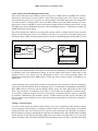
Figure 5: Mobile IP solves the problem of Figure 4. The Mobile Host (MH) registers with a Foreign
Agent (FA) which assigns it a temporary IP-Address. The Home Agent (HA) which keeps track of the
MH’s position has knowledge about this Address and encapsulates and forwards the arriving packets to
it. The FA decapsulates and delivers the original IP-Packets to the MH.
2.5 The Management Task
Within the context which was decribed in the preceeding sections of this Chapter, it is now possible to
state the requirements which the Network Management task is supposed to fulfill. Managing a communication system includes among other things controlling hardware interfaces and protocols. Fortunately
when developing a NM application one does not have to start from scratch with the implementation of
the protocol. As we will see in the introducton to the Simple Network Management Protocol (SNMP,
section 3.2) all SNMP applications have many things in common. The implementation of some of
these standard functionalities is available in software development packages. The requirements which
are specific to the Walkstation II project must still be analyzed and met. It is possible to look at the
required functionalities in two dimensions: a space dimension and a time dimension. This rather rough
view of things is refined in section 3.3.
Space dimension
If we look at the planned system in space, we establish that it is cellular. Let us consider the cell as the
medium level in the space dimension. Each cell has its own Base Station (BS) which routes the packets
to and from the fixed network. It also has its own virtual channel(s) and a set of Mobile Stations (MS)
inside its area. The requirements for NM at the cell level are: The control of the channel: This is done
by watching the number of users accessing it, the total power in the channel, the average values of the
Bit Error Rate (BER) and the Frame Error Rate (FER).
- Keeping track of the MSs which can be reached in the cell.
On a lower layer in space we find the various Stations (MSs and BSs) inside a cell, which definitely
page 11
SNMP Application for the MINT Router
need some individual management. The requirements to NM at the Station level are:
- Watching the received signal strength when a Station communicates with a correspondent.
- Control the transmitting power of a station
- Watching over the BER and the FER
- Checking the state of other channels from the point of view of the station, in regard to a possible
handover
The system which we consider as the highest level in space, consists of several cells. The requirements
for NM at the system level are:
- Assigning different CDMA codes to the virtual channels
- Watching the traffic distribution over the cells.
Time dimension
If we look at the NM system in time, we can state that not all the NM functions need to be invoked with
the same frequency and with the same realtime requirements. For instance, the assignment of the
spreading codes to the different channels does not have to be done as fast as the adaption of the transmitting power of a station. In the context of the NM task for the Walkstation II project, it is suitable to
classify the desired response times into three groups. Without insisting too much on this terminology,
we can call them, medium term (minutes..hours), short term (seconds), very short term (< seconds). We
will see in section 3.4 that response times which are significantly below 1 second (i.e., 1..10 ms), are
very difficult to handle by a NM process running at the application layer.
page 12
SNMP Application for the MINT Router
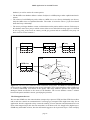
Spatial dimension
System manag.
Search for
a station
Cell manag.
Updating of
routing tabl.
Station manag.
Power
control
< seconds
CDMA key
allocation
Handover
execution
seconds
minutes
Time dimension
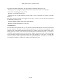
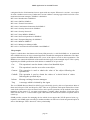
Figure 6: An example for the two dimensional representation of the NM functions. In the spatial
dimension we distinguish between the management of single stations, the management of cells and the
management of the system as a whole. The desired response time for the functions can roughly be
classified in three terms. It is obvious that we find a concentration of functions around the diagonal of
this diagram. The management of the system does not have the same realtime requirements as the
station management.
page 13
SNMP Application for the MINT Router
3 Network Management
This chapter, Network Management (NM), is structured into different sections. Section 3.1 treats general issues of NM. Besides the goals and the evolution of Network Management it contains considerations about how to classify the different tasks of Network Management and an overview on three
common management protocols. Section 3.2 gives an introduction to the Simple Network Management
Protocol (SNMP). It includes the architectural framework, the underlying protocol suite and the implementations of the protocol which are available on the Internet. Section 3.3 introduces the general structure of the SNMP Application for the Walkstation II Project. Section 3.4 contains issues concerning the
actual implementation. This section is completed by rather technical details in the Appendix.
Functional dimension
Security
Accounting
Performance
Fault
Configuration
Components
Planing
Realisation
Operation
System
Application
Enterprise
Time dimension
Scenario dimension
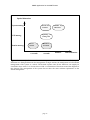
Figure 7: The issues of the wide Network Management field can be classified into three dimensions:
The scenario, the time and the functional dimension.
3.1 Overview on Network Management
Management of a communication system has always been a field where technical, economical and
political decisions had to be taken. Needless to say that the solution to a problem is often requires compromises between different interests, rather than being optimal from one point of view. Since there are
people with different backgrounds working in this field there are also different ways of classifying the
Network Management (NM) issues. However, the content of this report is limited to the technical
aspects of NM. Figure 7 shows the three-dimensional approach proposed in [3], which considers the
functional dimension, the time dimension and the scenario dimension.
The time dimension
The time dimension takes into account the different stages of a NM system’s life cycle. A system is
planned, then realised and finally runs. Each of these phases brings up its particular issues. This report
will mainly treat points of planning and realisation.
page 14
SNMP Application for the MINT Router
The scenario dimension
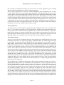
The nature of the managed system or subsystem influences strongly the management task. E.g., if single components are controlled, most of the management actions are likely to be invoked automatically.
If a whole subnetwork is managed there might be more human interactions required. Figure 7 shows
how the NM task for complex systems is often subdivided into different layers. At a lower level there
may be Management Processes which control several network nodes or even components of nodes.
They report (only the significant information) to a higher level process which has the overview on the
network. The various Management Processes may be distributed over the network or run all at the
same machine, as virtual subsystems. We will see in section 3.3 what implications this has to the NM in
the Walkstation II project.
The functional dimension
The ISO Management Framework distinguishes 5 different functional areas in this dimension. During
the configuration the parameters in the different nodes of a network are set in a suitable way to interconnect the stations. The fault management is in charge of keeping the availability of the network as
high as possible. It detects isolates and tries to repair faults. The performance management tries to control and improve the characteristics of the available network (e.g., response time, throughput). An
important role of the accounting management is charging the user for the obtained services. The security management provides for data protection and prevents the abuse of network resources. A more
detailed information of the functional dimension is given in [3].
Top
level
Mangement
Process
M. Proc 1
M. Proc 2
M. Proc 3
Subnet 2
Subnet 2
Subnet 2
Managed Network
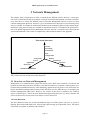
Figure 8: Management Applications are often structured into independent management subsystems,
each controlled by its own Management Process which reports to a Management Process with a more
global view. The subsidiary processes filter out detail information which of no concern to the global
Manager. They can be distributed over the network or run on the same management station,
representing virtual subsystems.
System Management, Network Management, Integrated Network Management
In the past, a difference was made between System Management and Network Management. System
Management is the task of exploiting a computer in the best possible way, watching hardware devices,
page 15
SNMP Application for the MINT Router
scheduling program executions, etc. In the beginning, computers existed in a small number, were
bulky, expensive and barely interconnected. In this situation there was no need for integrated management, i.e., management systems which allow for controlling products of different vendors from one
management platform. Each system had its own management facilities. When systems got more and
more interconnected, managing the interconnection framework became an issue. In this context, the
managed systems are routing and switching equipment with all their hardware devices and the software
running on them. This task is referred to as Network Management. The next trend was towards distributed computer networks where the processing power was spread out over the network (workstations,
PCs). Data also started to be stored in a distributed manner, still being available from any point in the
network. Therefore, the degree of interconnection increased again. The difference between System
Management and Network Management now became fuzzy, since managing one could not be done
without managing the other. With this evolution, integrated NM became definitely desirable. They
were needed to control the resources of data networks, detecting and repairing failures, etc. Of course,
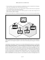
Integrated Management was a hard job without standard management interfaces, as the nodes in a network came from different vendors. A management application had to be able to connect to all kind of
page 16
SNMP Application for the MINT Router
interfaces and handle data structures for all the managed entities (Figure 9 a). To avoid this kind of
Management
System
Sch 1
Managed
System 1
Sch 2
Sch 3
Managed
System 2
Managed
System 3
Heterogeneous internet
Figure 9 a: Sch 1 - 3 = System specific NM schemes
Management
System
Standard scheme
Managed
System 1
Managed
System 2
Managed
System 3
Heterogeneous internet
Figure 9 b
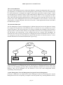
Figure 9: Network Management Systems are faced with networks which interconnect systems of
many different vendors. In the past, an NM system had to support all the management schemes specific
to the different kind of equipment (a). This made the development of NM applications very complex
and inflexible. Today there are different standards of NM protocols. The task of supporting the standard
management interfaces for the devices with their specific features is shifted towards the manufacturers
who know their products best. To the NM Applications the vendor specific characteristics become
transparent.
problems, the NM standard protocols were created. They brought abstraction of many system specific
details about managed devices and allowed designers of NM applications to focus on their actual task
of managing subsystems (Figure 9b).
page 17
SNMP Application for the MINT Router
Some common Network Management Protocols
Some of the NM frameworks which are widely used [2] are: CMIP, CMOL and SNMP. The Common
Management Information Protocol (CMIP) is part of the OSI protocol suite. The Common Management information protocol Over logical Link control (CMOL) is the IEEE approach to the management
of LANs. Its name is confusing since some of the IEEE LANs may not use CMIP. The Simple Network
Management Protocol (SNMP) is used in the Internet together with the TCP/IP protocol suite. As the
NM Application for the Walkstation II project is based on SNMP, section 3.2 is dedicated to explain the
SNMP framework in more detail.
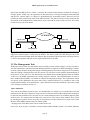
These three frameworks follow the same general principle which is mainly based on three elements
(Figure 10: the Management Process (or Manager), the Agent (or Agent Process) and the Management
Information Base (MIB). The Management Process executes at the Management Station (MS). It sends
MIB
Manager
internet
Agent
MIB
Management Station
Managed devices
Managed station
Figure 10: The three basic elements of a Network Management system: The Agent is the process
executing at the managed entity. It has direct access to the managed objects. The Management Process
(or Manager) runs at the Management Station. It asks the Agent which actions it must apply to the
managed devices. The Agent and the Management Process have both knowledge about the
Management Information Base (MIB) which contains the object resources which are handled by an
Application.
control messages to the Agent which executes at the managed entity and takes locally the corresponding measures. The information about the managed objects is contained in the Management Information
Base (MIB) which is known by both the Manger and the Agent. The three approaches to NM are all
fairly “object oriented”. In computer sciecne object oriented stands for an approach to software analysis, in which a computer program is based on a framework of elements (objects) which are described
by attributes (information) and methods (actions). A MIB contains typically objects describing the
state of a whole system, hardware devices, physical interfaces and programs, in particular communication protocols.
Polling versus Interrupts
As in any control system, the question about polling or interrupt is important in NM. Should a control
process regularly send messages to a managed system in order to check its state (polling), or should the
managed system notify the control process of special events (interrupt)? The advantage of polling is
that the manager can always distinguish the importance of different tasks, and schedule them according
to their priority. On the other hand, polling might cause more unnecessary data traffic, as it is also done
when everything is OK. Generating interrupts when something needs to be done, is optimal with regard
page 18
SNMP Application for the MINT Router
to data traffic. Its main disadvantage is that it is hard for the manager to distinguish important interrupts
from harmless ones. By assigning different priorities to types of interrupt, things usually get very complex, as this priority order depends strongly on the scenario. Therefore, many Network managers prefer
the polling approach, except for serious events. In these cases the Agents have to become active and
send a message to the Manager, without being queried (e.g., system failure and system start-up). These
interrupt-like messages are known as notifications in the OSI framework and as Traps in the Internet
Framework.
Some differences between the mentionned standard protocols
There are still many differences between the different NM approaches. The rules for defining OSI managed objects resemble much to the ones applied by modern Object Oriented Programming Languages.
E.g., they include inheritance which is not used by SNMP. SNMP does not even distinguish between
attributes and objects but rather treats attributes like objects[2]. As the IEEE framework includes part
of the OSI documents in its standards, it is very similar to the OSI framework. There are also major differences in the methods which apply to objects. A quite fundamental gap between OSI and Internet
NM is that OSI managers believe in connection oriented transport services in order to make sure that
the sent messages always reach their destination. Internet mangers do not, arguing that emergency
management in a congested network is more likely to succeed with connectionless transport services.
Retransmissions are therefore handled “manually”, i.e., by the Application Layer.
Interconnection of NM subsystems using different protocols standards
Since CMIP and SNMP are both established in interconnected data networks we find the problem of
managing hybrid networks (Figure 9) again on a higher level [3]. An NM system is potentially in
charge of managing parts of two networks which use different NM protocol standards. For this reason,
there are CMIP programs running on the top of the TCP/IP protocol suite and SNMP programs running
on the top of the OSI protocol stack. They are referred to as “CMIP for the Internet” (a successor of
CMOT) and “SNMP over OSI”.
3.2 An Introduction to the Simple Network Management Protocol (SNMP)
The History
In 1988, the first SNMP specifications were finished. At that time there were very few network management applications or protocols available. Much of the networking infrastructure (gateways and
servers) was built on UNIX™ platforms. That was a good starting point for free and commercial
SNMP/UNIX products. These products took over in Internet management and soon met the customer’s
most pressing needs. Like all Internet standards SNMP is defined in a so called Requests for Comments
(RFC):
RFC 1155 “Structure of Management Information (SMI)”
RFC 1157 “Simple Network Management Protocol (SNMP)”
RFC 1212 “Concise MIB definitions”
RFC 1213 “Management Information Base (MIB-II)”
After some time, the customers started to ask for more security and less traffic overhead due to NM. In
199? it was time for version 2 of SNMP, which is often referred to as SNMPv2. To improve security
SNMPv2 adds two mechanisms to the framework, one for authentication and one for data encryption.
To help improve performance a new message type is supported which allows the manager to retrieve
page 19
SNMP Application for the MINT Router
contiguous blocks of information from an Agent with one request. Whereas in version 1, one request
for each variable was necessary. Furthermore version 2 defines a message type which is used in a communication between managers. SNMPv2 is defined in:
RFC 1441 “Introduction to SNMPv2”
RFC 1442 “SMI for SNMPv2”
RFC 1443 “Textual Conventions”
RFC 1444 “Conformance Statements for SNMPv2”
RFC 1445 “Security Protocols for SNMPv2”
RFC 1446 “Security Protocols”
RFC 1447 “Party MIB for SNMPv2”
RFC 1448 “Protocol Operations for SNMPv2”
RFC 1449 “Transport Mappings for SNMPv2”
RFC 1450 “MIB for SNMPv2”
RFC 1451 “Manager-to-Manager MIB
RFC 1452 “Coexistence between SNMPv1 and SNMPv2”
The principle
Figure 10 which shows the framework of many NM protocols, is valid for SNMP, too. As mentioned
above SNMP also uses an object oriented approach to handle the management information. The Management Information Base (MIB) defines the syntax of the objects as well as their organisation. The
MIB does not contain the definition of the methods which apply to the managed objects. This is partly
implied by the SNMP specification which defines a standard set of operations:
Get
This operation is used to obtain a value of an identified object
Set
This operation is used to set a value on an object
Getnext
This operation is used to obtain the value of the object following the
specified one
Getbulk
This operation is used to obtain the values of a whole block of values
following the specified object
Inform
Message exchange between managers
Trap
A message which is initiated by the Agent
The set of SNMP Protocol Data Unit (PDU) types is basically given by this set of operations. Most of
them need a Request-PDU and Response-PDU. This set of operations looks quite limited for a framework which claims to be object oriented. In fact, more specific operations can be realised in the implementation of the Agent. E.g., an agent could support a variable called “bootFlag”. Each time a SetPDU with the value “1” is received the Agent could reboot the machine and send a Trap-PDU when it
is back up.
SNMP provides a means for managing devices which do not support the TCP/IP protocol suite (e.g.,
repeaters). An SNMP-Agent executing on another machine can take care of such an agent and report its
state to the Manager. This is known as a Proxy relationship.
page 20
SNMP Application for the MINT Router
The Management Information Base (MIB)
A Management Information Base (MIB) is supposed to specify the object resources which are supported by a given SNMP application. The objects of an SNMP MIB are represented in a tree structure
which resembles to a file system in a computer (Figure 10).
MIBs are written using a set of rules called Structure of Management Information (SMI) which is
defined in the RFCs 1155 and 1442. SMI is based on ASN.1 notation but adds further conventions to it
by restricting strongly the number of supported ASN.1 types and adding some ASN.1 macros to define
objects, textual conventions (which is similar to ASN.1 subtyping), etc. The resulting text file containing a MIB turns out to be barely readable. For this reason it is desirable to have a browser tool for looking at MIBs. Appendix A contains a description of the browser tool which was developed by the author
while at the TS Lab.
Many of the SNMP-managed Internet nodes have a common set of basic features (for instance the
specification of their communications interfaces, or the protocols they use). The corresponding object
resources are known as the standard MIB specified by Working Groups of the Internet Engineering
Task Force (IETF) in RFCs. Figure 10 shows an extract of the standard MIB. Its existence is not only
essential for developing Network Management (NM) applications, it also helps interoperability of NM
products released by different suppliers. There is a clear need for defining objects which describe the
specific properties of the managed network entities, for instance the configuration parameters of the
new radio device for the MINT Router. This leads to enterprise specific MIBs, which are integrated
into the MIB tree under a branch called enterprises. MIB developers have to acquire a subtree number
under the enterprise branch from the Internet Assigned Number Authority (IANA). The assignments are
made via E-Mail. For instance, the number we got for our enterprise specific MIB is 933 and the actual
structure of the subtree under this branch is then left to us.
mib-2(1)
system(1)
sysDescr(1)
sysObjectID(2)
interfaces(2)
......
ifNumber(1)
......
ifTable(2)
ifEntry(1)
ifIndex(1)
ifDescr(2)
ifType(3)
......
Figure 11: The organization of objects in an SNMP MIB resembles to the structure of subdirectories
in a Filesystem. Only leaf objects can represent variables. Non-leaf objects are just used to represent
subtrees of the MIB. The figure shows parts of a subtree extracted from the standard mib-2. Each
branch has a textual name (label) and an index (subidentifier). Labels and subidentifiers can both be
used to form an Object Identifier, i.e. the specification of the whole path leading to an object.
A “path” leading to an object in a MIB is specified by an object identifier. In other words, an object
identifier is a registration point in the MIB tree. Such a registration point may simply be a placeholder
for a subtree, or it may define a syntax (i.e. a “type”) of a managed object. The SNMP terminology
page 21
SNMP Application for the MINT Router
makes an important difference between objects and variables. A variable consists of an object identity
and an associated instance. Therefore, simple variables are found at the leafes of the tree. (The definition of tabular objects is somewhat more complex [1], [13].) Variables are the operands in SNMP operations.
A MIB contains the object definitions of an SNMP application. It does not contain the actual values of
the variables and thus it lacks the facilities of a common database system. Unfortunately, the SMI is
also far from being a data base language. Conceptual variables and conceptual rows of a table are frequent terms in the SNMP literature. They simply mean that if an object is defined in a MIB as accessible (e.g., read-write), the Agent is supposed to handle its instance, i.e., to execute GET and SET
operations on its value. The management process has no knowledge about where and how the value of
a variable is physically stored. It can be read from (resp. written to) a device driver, every time a GET
(resp. SET) command is received, or it can simply reside in the memory of the managed entity. As
there is no uniform way to handle object instances the task of a database language starts where the one
of the MIB stops. Consider for instance the standard data base problem of consistency when data of
Table A depends on some data of Table B. The SNMP Agent has a priori no means to check how a conceptual variable relates to another. Therefore, there is a set of simple rules that MIB designers apply,
which do not necessarily correspond to the principles of data base languages, e.g.[13]:
“Too much information creates as much a problem as not enough information. Begin
slowly and try to specify only the key objects to be managed.”
“Objects must have demonstrated current use and should not define as placeholders for
future implementation.”
The security schemes and the Parties
[1] states that “an SNMPv2 party, or simply a party, is an execution environment residing in an agent or
management application.” The notion of party was added to the SNMP framework by version 2. Parties are used in the context of security in order to identify the different actors and their rights in a NM
system. With other words an entity which is involved in a management system (Agent or Manager) is
known to the others by a correspond entry in their party data base. Such an entry has associated with it
three sets of attributes: the transport attributes, the authentication attributes and the privacy attributes.
The transport attributes specify the parties network address and portnumber, as well as the used transport protocol (usually UDP). The authentication attributes specify basically the used authentication
scheme and the secret codes. There are currently only two authentication schemes in the proposed
standards: noAuth (no authentication) and the v2md5AuthProtocol which is based on the MD5 Message-Digest Algorithm [RFC 1321]. Eventually, the privacy attributes specifies the data encryption
scheme. There are also two possibilities for encryption: the noPriv protocol (no privacy) and the
desPrivProtocol which is based on the Data Encryption Standard (DES) [US Federal Information
Processing Standards Publications #46-1 and #81].
Let us look at this security scheme from a practical point of view. The current NM application for the
Walkstation II project, makes use of the trivial scheme for authentication and encryption (i.e., noAuth
and noPriv). This still does not mean that an Agent accepts all sort of requests, wherever they come
from, concerning any variable. Before an Agent becomes operational it must be configured carefully,
i.e. it must be told exactly which party has access to which variables with which priority. In order to
create this relation between objects and parties, SNMPv2 needs four different data bases: One for parities, one for MIB views, one for contexts and one for access privileges. Let us look at each in turn.
• The party database contains the information which a party has about its correspondents. As we have
seen above, this database specifies for each party its transport, authentication and privacy attributes.
It contains entries for parties which execute locally (i.e., at the same location as the owner of the
page 22
SNMP Application for the MINT Router
database), as well as entries for remote parties.
• The the MIB view database defines a subset of objects in a MIB (using a rather sophisticated mechanism).
• The context of an SNMP party refers either to a MIB view or to a Proxy relationship (see above).
Only the MIB views are explained hereafter. The reader is invited to refer to [1] for more detail
about the Proxy relationship.
• The access privileges database creates a relation between the parties and the contexts. Each entry to
this database states for a party to which context it has access and which message types it is allowed
to use (e.g, party_n has access to context_m with get, get-next and set commands). One party can
have access to several contexts.).
Context
Party
Access privilges
MIB
mib-2(1)
MIB view
......
......
interfaces(2)
ifNumber(1)
ifTable(2)
ifEntry(1)
ifIndex(1)
ifDescr(2)
ifType(3)
......
Figure 12: The roles of the databases which contain the security data. The MIB View database defines
object groups in a MIB to which the same access rules apply. The Context database refers to MIB view
or a Proxy relationship (not shown in the figure). The Party database specifies the Agents and
Managers which are known to the owner of the database. The Access database creates a relation
between the parties and their context, specifying the priorities.
The Management Process
We saw that SNMP uses the connectionless transport layer protocol UDP, and that UDP does neither
end to end error control nor retransmission if a message got corrupted. This might seem risky for an
application which is supposed to keep a network running. If error detection and retransmission is not
done at the transport layer, this does not mean that it is not done at all. It is simply left to higher layers.
SNMP may still handle sessions, how the OSI model suggests to do in protocol layer 6. This can imply
page 23
SNMP Application for the MINT Router
that a message is retransmitted as long as no correct answer is received. Appendix B gives an insight
into how session are handled in the CMU development package.
The first thing a Manager does at start-up is read the MIB and the Party configuration files. It knows
now the Agents which it has to communicate with. Depending on the implementation it opens sessions
with the agents. Each session might follow different schemes. One might need Authentication without
Encryption, another might need both and a third one none of them. The Manager is now ready to start
its work sending out Request messages and accepting Reply messages. It is basically a control process
with all the problems from realtime requirements to emergency management, etc. As many processes
in industrial contexts it has also the capability of extending the set of managed devices at runtime (e.g.,
a router which was down is brought up and sends a start-up trap). It might also change the schemes of
management sessions (e.g., change to data encryption mode).
The Agent Process
The agent process is usually simpler to program than the management process. It is normally a daemon, i.e., an invisible server which runs as a background job. Similarly to the Management Process, at
start-up time it reads the MIB and Party configuration files to know which variables it is supposed to
handle, which manager is allowed to send Requests and to which it must send traps. It then waits for
incoming requests and local events which ask for a reaction. Since an Agent does usually not run on a
dedicated machine, its code should be as small as possible and require little processing time.
The implementations
There are several software development packages which implement the SNMP standard. They consist
of libraries written in the C programming language. Different modules are usually merged to one big
C-code library. The modules implement thematic blocks of functionalities. E.g., one module contains a
MIB compiler which generates C data structures from object definitions in SMI/ASN1. Another one
handles the transport layer services. Using these libraries, allows the programmer of a new application
to focus on the application specific issues. Some of the implementations are freely available on the
Internet. Most of them are released by universities, which do research in the NM domain. Unfortunately, most providers of public domain software put little effort into writing manuals for their code.
This is also true for the SNMP development packages. Three of these software development packages
were installed on the computer system of the Telecommunication System Lab in order to check
whether they were suitable for the needs of the current NM application. No experiments were made
with commercial software. The “SMP Development Kit” was created by the Massachusetts Institute of
Technology (MIT), the “CMU-SNMP2 by the Carnegie Mellon University (CMU) and the ISODESNMPv2 by Marshall T. Rose from Dover Beach Consulting, Inc. Using the programming libraries
often turns out be troublesome.
The installation of the “SNMP Development Kit” (MIT) is rather straightforward but it is poorly documented and its library code is not commented at all. Furthermore, it does not support version 2 of
SNMP. ISODE-SNMPv2 was hard to install on the local system in the TS lab. This is due to the fact
that it is probably the most complete package, and thus very complex. A general rule for installing software is that the (uncompiled) source code of a module takes three times less disk space than the resulting executable programs. About 40 of the impressive 53 MBytes of source code which must be
installed for using ISODE-SNMPv2 is actually the ISODE (ISO Development Environment) package.
The advantage of this package is that there is literature about this particular implementation. Unfortunately, it caused a lot of trouble during runtime, so that it had to be considered unsuitable for the Walkstation II Management. Especially if one takes into account that the application must be compiled and
debugged in a crossdevelopment environment, the libraries should be programmed in a readable, relia-
page 24
SNMP Application for the MINT Router
ble and extendable way rather than be very complete and highly sophisticated. The SNMPv2 package
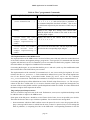
(by the CMU) matched better this required profile. Table 1 summarizes the features of these three software packages. In its last column, “comments” stands for the comments included in the library source
code.
Table 1: Comparison between SNMP development packages
Name
Supplier
SNMP
versions
Package
size
Installation
Documents,
comments
Development Kit
MIT
1
1.3M
feasible
poor
ISODE-SNMPv2
M. T. Rose
1 and 2
53 M
difficult
good
CMU SNMP
CMU
1 and 2
7.2 M
easy
satisfactory
There are two more public domain implementations of SNMP which are widely used and accepted by
the Internet community. “Tricklet” is a product of the Delft University of Technology, Netherlands. It
uses part of the ISODE-SNMPv2 package for the MIB compilation. The most recent implementation
of SNMP was released in late 1993 by the Twente University of Technology, Netherlands[17]. Unlike
the other implementations it uses the multi tasking facilities of the UNIX™ Operating System. The
SNMP Protocol Machine (SPM) is one task which communicates by means of interprocess communication with the management application. Multiple applications may use the same [17] SPM. This can
be interesting especially for large, multilayered NM applications(Figure 7).
3.3 The Design of the SNMP Application
This section describes the architecture of the SNMP Application for the Walkstation II project. It does
not consider details of the implementation using the CMU software development package. It actually
shows the NM framework of a system which should meet the requirements for NM (stated in 2.5) for
the mobile communication system (sections 2.1- 2.4) using SNMP (section 3.2). This section has four
subsections. Section 3.3.1 shows how the NM functionalities can be classified into blocks. From these
considerations will follow the Information which is present at the entiities (3.3.2) and the functional
blocks of the Agent (3.3.3) and the Manager (3.3.4).
3.3.1 The different NM functionalities at two levels
In section 2.5 we looked at NM requirements in space and in time. In space we distinguished requirements for station management, cell management and system management. In section 3.1 (Figure 7) we
saw that it is ofen desirable to organize the management functionalities at diffent levels. Let us recall
that subsidiary Managers can control clusters of machines or even subnetworks. They report to the
higher level Managers by filtering out the detailed information which is not of concern from a global
point of view. When specifying the actual Manager and Agent processes in this section, we will see
that the spatial considerations of section 2.5 are valid to some extent for the description of the two NM
levels. They still need refinement if we look at the functional blocks inside the Manager and Agent
tasks.
Due to the cellular structure of our system, it is suitble to control single cells at a lower NM level and
the whole system at a higher level. The advantages of this approach are obvious:
• If the cells are managed independantly, the system remains still avaible even if a break down of a
single cell occurs.
page 25
SNMP Application for the MINT Router
• The cell is likely to be the unit by which the communication system is extended. The cell management is the corresponding unit by which the NM can be scaled.
• The cell management can take care of the functionalities which have hard real time requirements
(e.g., the power control of the mobile transmitters)
• From a project management point of view, it will be possible to run and control a single test cell
before the whole system is installed.
So far we have decided to run a dedicated management process for each cell and one global manager
Manager
Top MS
LAN
Man./Ag.
Man./Ag.
BS-MINT 1
BS-MINT 1
LAN
LAN
Agent
Agent
MH-MINT 1
MH-MINT 2
Figure 13: A possible NM configuration which corresponds to the top down structure of a traditional
mobile communication system. Although it looks quite simple in this scheme it is more difficult to
realize than the current approach (Figure 14). One reason is the limited processing power of the BSMINTs.
controlling the cell managers. The question is now which different kinds of processes we need and on
which machines they should execute. As we saw in section 2.2 a MINT has basically the same capabilities for running UNIX programs as a small SUN Microsystems workstation. On the other hand it is
possible to implement dual role SNMP entities [1] which have at the same time a manager role and an
agent role. So a possible solution to the problem would be that a Base Station (BS) MINT runs such a
dual role entity with a manager communicating with the Agents at the Mobile Stations (MS) MINT and
an Agent serving the queries from the top level Manager (Figure 13). This approach which is inspired
by the top down hierarchy of traditional mobile communication systems, is not suitable for the Walkstation II management for several reasons. As we stated in section 2.1 the relationship between BSMINTs and MS-MINTs is basically symmetric, at least in hardware, and thus, the managed objects in a
page 26
SNMP Application for the MINT Router
BS-MINT and in an MS-MINT are mostly the same. Furthermore, running a manager process needs
more processing power than running an agent process. The processing load will increase when more
MSs are being served in a cell. Running a dual entity on a BS-MINT could easily overburden it with
management processing and prevent it from doing its actual job, the routing.
Figure 14 shows the configuration which we chose for the Walkstation II NM. In this approach, the cell
manager executes at a workstation connected to the fixed network. This structure takes into account the
symmetry of the relationship between BS-MINTs and MS-MINTs. Another advantage of this approach
is that we can manage with one enterprise specific MIB and one type of Agent process for all the
MINTs. This is an important aspect of the software development.
In the rest of this section we only consider cell management. Due to lack of time it was not possible to
work on the implementation of the top level management.
Manager
Top MS
LAN
Manager
Manager
MS 1
MS 2
LAN
LAN
Agent
Agent
BS-MINT 1
BS-MINT 2
LAN
LAN
Agent
Agent
MH-MINT 1
MH-MINT 2
Figure 14: The current configuration of the MN system of the Walkstation II project. The
management processes running at the Management Stations MS 1 and MS 2 control one cell each and
report to a global management process which controls the whole system. All the MINTs run the same
type of Agent supporting one universal MINT-MIB.
3.3.2 The MIB
Having fixed the configuration of the NM processes, we now need to look at the set of managed objects
page 27
SNMP Application for the MINT Router
in a MINT. The MIB which is supported by a MINT consists of two parts: The standard MIB which
must be supported by all conforming SNMP managed entities, and the MINT specific enterprise MIB.
Let us consider each in turn.
The standard MIB
The standard MIB is defined in RFC 1213. Its full label is MIB-II. It defines object groups (i.e., subtrees in the MIB structure) concerning the system (i.e., the managed machine), the (physical) interfaces
and the protocols (ip, icmp, tcp, udp, ...). The MIB-II definitions can be found in the file mib.txt which
is included in the CMU package. This MIB moudule is supported by the sample agent of the CMU
software development package. As the MINTs use rather Mobile*IP than IP as network layer protocol,
the MIB-II needs to be completed by some mobileIP group in MINT-MIB module. This part has not
been realized yet.
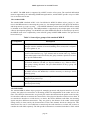
Table 2: Some object groups of the standard MIB-II
Group label
Description
system
Mainly textual information about the managed system which tells a (human)
manager were the machine is located (building, floor, room) who is responsible for it (phone #), etc.
interfaces
Description of the machine‘s physical interfaces. Besides the general properties the of the interface (e.g., type, bitrate) and its current state (e.g., number
of discarded packet since last reboot), this group contains a pointer to an interface specific MIB module.
at
The address translation group consists of a Table which allows for mapping
of Network addresses (IP addr.) to Physical addresses (e.g., Ethernet addr.).
This group is being obsoleted. The ipNetToMediaTable of the ip group will
take over its role.
ip
The internet protocol group contains information about the IP machine. As
the MINT will run the Mobile*IP, it will be necessary to develop a similar
mobileIp group.
tcp
This group contains objects describing the state of the connection oriented
transport layer protocol tcp.
udp
This group contains objects describing the state of the connectionless transport layer protocol udp.
The MINT-MIB
The standard MIB-II defines object groups for managing protocols and physical interfaces. In wired
systems, the (physical) caracteristics of incoming packets are independant of the sender and its distance. The electrical characteristics are given by the station which forwards the packet on the last hop.
It is therefore sufficient to measure the caracteristics of the physical interface which receives them. If
we consider the interface to a radio device, we notice, that for the different radio links, the incoming
signals may have different caracteristics. They are given by the distance of the sender (which might
change slowly in time) and by the characteristics of the radio channel which can change fast. This
shows that in our case, it is not sufficient to control only the radio interface as a whole, but we have to
consider the radio links separately. The link specific information is contained in the Router Table which
page 28
SNMP Application for the MINT Router
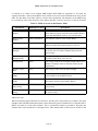
is referred to as rtTable in the module MIB module MINT-MIB (see Appendix C). Its fields are
explained in Table 3. Each remote MINT router which can be received and reached has an entry to this
table. The first field, Local MAC Address, needs a short explanation. The hardware of the MINTs may
be extended by more radio interfaces in the future and thus it will be necessary to specify the MAC
Table 3: Fields of a row in the Router Table
Field Name
MIB Object Label
Description
Local MAC
Address
rtLocLinkAddress
The Ethernet Address of the local radio LAN interface
which must be used to reach the remote MINT Router.
Especially BS-MINTs can have serveral interfaces.
Remote MAC
Address
rtRemLinkAddress
The Ethernet Address of the remote MINT
Channel Identity
rtChannelId
A pointer to a row in the Channel Table describing the
channel on which the remote entity is received
Designate Signal
Strength
rtDss
The transmitted signal strength to which the local radio
device has to be set when communicating with the
remote entity
Received Signal
Strength (RSS)
rtRss
The signal strength with which the last incoming frame
from the remote entity was received
Average RSS
rtErss
The average of the received signal strength taken over a
number of samples which is carefully chosen by the
implementor
Variance of the
RSS
rtVrss
The average of the received signal strength
Bit Error Rate
(BER)
rtBer
The Bit Error Rate which is measured in the communication with the remote MINT Router
Frame Error Rate
(FER)
rtFer
The Frame Error Rate which is measured in the communication with the remote MINT Router
Last Received
Time Stamp
rtRecTstamp
The Time Stamp of the last received packet from the
remote entity
Last Sent Time
Stamp
rtSentTstamp
The Time Stamp of the packet which was last sent to
the remote entity
address for each.
When considering single radio links we still notice, that they have some features in common. The agent
should be able to handle information about a radio channel in general. Furthermore it is desirable that a
MINT can listen to several radio channels. This is essential for handover procedures. Therefore the
channel data is also contained in a conceptual table. This channel table is referred to as chTable in the
page 29
SNMP Application for the MINT Router
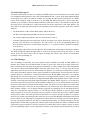
MINT-MIB module. Each radio channel which is known to a MINT is represented by a row entry.
Table 4: Fields of a row in the Channel Table
Field Name
MIB Object
Label
Description
Channel Identity
chId
The (integer) identity of the channel. The value of
this field corresponds to the one of the field rtChannelId for the actual users of the channel
Spreading Code
chSpreadCode
The Spreading Code which is being used by the
entities accessing the channel
Average of the
Average RSS values
chEErss
The average taken of the values in the column
rtErss of the Router Table
Average of the
Variance of the
RSS
chEVrss
The average of the values in the column rtVrss of
the Router Table
Average of the
BER
chEBer
The average of the values in the column rtBer of
the Router Table
Average of the
FER
chEFer
The average of the values in the column rtFer of
the Router Table
Total power in the
channel
chTotPower
The total energy measured in the channel.
Number of Users
in a Channel
chNumbMh
The number of MINT Routers which are using the
channel (including the Base Station)
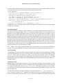
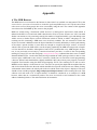
Eventually, there is a relation between the router table and the channel table, as every link has an associated radio channel. Therefore a field in the router table contains the index of the used radio channel,
i.e., a pointer to an entry in the channel table. Figure 15 illustrates the relation between the router table
and the channel table. It also shows how a mobile station can listen to different channels.
page 30
SNMP Application for the MINT Router
RouterTable
MS 1
.....
MS 2
.....
Channel Table
CH 1
.....
BS 1
MS 1
MS 2
RouterTable
MS 1
.....
BS 1
.....
MS 3
.....
BS 2
.....
BS 2
Channel Table
CH 1
.....
CH 2
.....
MS 3
Figure 15: A simple example for entries to Router and Channel Tables. The Base Stations (BS) and
the Mobile Stations (MS) use the same virtual channel (CH n) to communicate within a cell. MINTs
can still listen to channels which they are not using. The Figure shows only the information known by
BS 1 and MS 2. BS 1 listens to channel CH 1 and has knowledge about MS 1 and MS 2. MS 2 listens
to CH 1 and CH 2 and thus, has knowledge about MS1, MS 3 and MS2. It is important to note that the
structure of the Management Information Base at a MS is identical with the one present at a BS.
3.3.3 The Agent
Since the MIBs for the BS MINT and mobile MINT are identical, both agent processes are of the same
nature, too. An SNMP agent process is usually run as a daemon, i.e., a server like background process.
The development of the agent can also be considered in two parts, one concerning the standard MIB
and one concerning the enterprise specific MINT-MIB moudule.
The standard MIB-II support
An agent which supports the object resources of the standard MIB-II is included in the CMU software
package. It could be installed on a Sun Microsystems SLC UNIX machine which has approximately
the same processing power as a MINT. The realisation of the corresponding part for the MINT agent
consists of porting the code of the current CMU agent to the MINT hardware. In the frame of the current NM system for the Walkstation II project, some experience was made with the crossdevelopment
environment described in the first intermediate report in the Appendix. Unfortunately, due to lack of
time this part of the work could not be achieved. With the new version of the MACH kernel for the
MINT which will be able to run a UNIX emulator, the crossdevelopment environment remains still in
use.
page 31
SNMP Application for the MINT Router
The MINT-MIB support
For the time until the device driver is available, the MIB variables are all contained in a structure which
is a straightforward translation of the ASN.1/SMI definition into C types. In the final implementation
of the agent, there will be no uniform manner of accessing the radio specific parameters of a MINT
router. Some variables reside in memory (e.g., the BER and FER measured for a given radio link).
Another set of variables is directly obtained from the radio device driver. The radio device driver and
the agent process will both have a table with entries for all the radio links to the other MINTs. The
driver fills in its table with measurements corresponding to the incoming packets. Each entry contains
fields for:
• The identification of the remote MINT (MAC and IP adresses)
• The Received Signal Strength (RSS) of the last received packet
• The average Signal Strength since the last call to the device driver
• A number indicating the state of the link. It allows the agent to see if there has been any activity on
the link since the driver was polled last. The link can be new if the corresponding MINT was
received for the first time. It can be known but passive, i.e., no power control is needed. Eventually,
it can be active.
• The spreading code which is used on the link. This information can be used to identify the channel.
The field Designated Signal Strength (DSS) is written by the agent and read by the driver. At each
device driver the device driver and the agent exchange their tables. This scheme of information
exchange is not operational yet.
3.3.4 The Manager
The cell manager is basically one process which controls variables on the BS and MS MINTs. For
instance, the creation of a Get Request PDU in order to retrieve the value of the average Frame Error
Rate in a channel, does not need any particular explanations. A rather complex part of the management
is the power control of the Mobile MINT. Since the radio device driver is not yet ready the current
application does not deal with real measurements. Its purpose is to study the mechanisms of synchronous and asynchronous requests and to make performance measurements. The fact that the cell management process is executed on a workstation rather than on the BS MINT (subsection 3.3.1) implies
that during each iteration of the power control loop, two Request PDUs must be sent to MINTs: The
manager first has to retrieve the Received Signal Strength (RSS) from the Base Station. Then it sends a
Set PDU concerning the Designated Signal Strength to the Mobile MINT (Figure 16). If we take into
account the expected coherence time of the channel of about 20 ms, we get aware that the execution of
the power control loop in realtime is particularly critical. The goal is to execute the power control loop
roughly 100 times per second. So far, this performance was not achieved. The CMU software development package contains a set of sample manager programs for generating Get or Set Request PDUs.
They use a synchronous request scheme, i.e., the manager remains blocked on a given request until
either a response is received or the request times out. Figure 16 shows that this is not a suitable method
for the power control. The time span between the release of a request and the reception of a response
must not me wasted with waiting because there may be several other BS/MS relationships which need
power control as well. Therefore an asynchronous scheme had to be developed. In the current application the Get Request PDUs for the RSS are generated periodically, by internal interrupts. The Set
Request PDUs for the DSS are generated at the reception of the Get Response PDU for the RSS. In the
synchronous request scheme it is trivial to associate a response PDU with its context, as there is always
just one outstanding request. In an asynchronous scheme, an incoming response PDU has first of all to
page 32
SNMP Application for the MINT Router
be associated to its request.
BS
MINT
MS
MINT
Cell Manager
Get Request RSS
Get Response RSS
Compute DSS
Set Request DSS
Set Request RSS
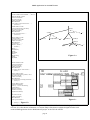
Figure 16: The message exchange during one cycle of the power control for the MS transmitter. The
manger asks the BS how strong the signal received from the MS is (RSS = Received Signal Strength).
It computes the Designated Signal Strength (DSS), i.e. the signal strength at which the MS-MINT
should send. Then it asks the MS to adapt the DSS. The execution of the power control loop in realtime
is critical.
So far the manager program which runs on a SUN SPARC workstation pretending to manage one BSmobile MINT relationship. (The corresponding agents also execute on workstations.) If the signal
strength of N mobile MINTs in a cell has to be controlled, the message exchange diagram of figure Figure 16 will be modified to one Get Bulk Request from the manager to the BS MINT, in order to read the
received signal strength on the N radio links. At the reception of the reply, the management process
will send a set DSS request to all the active mobile MINTs which need to adjust their signal strength.
The Get Bulk Response will actually inform the manager about the state of a radio link (active or idle)
and about new mobile MINTs for which a power control session must be set up.
3.4 The Implementation
3.4.1 The Agent
For the time until the device driver is available, the MIB variables are all contained in a structure which
is a straightforward translation of the ASN.1/SMI definition into C types. Extensions to the CMU agent
were necessary to support the new set of variables. The reader who is interested in these practical
details is referred to the Appendix B.
Recently, the prototype of a device driver, called radionet, which provides the same interface as the
future radio device driver, was developed by Pascal Guerin in the TS group of KTH. It can be launched
page 33
SNMP Application for the MINT Router
on a SUN Microsystems workstation. Its principle is that the device driver and the SNMP agent have
each a table with an entry for each radio link and with the following fields:
struct MHPARAM {
char ether[6];/* ethernet address of the mobile host */
char ip[4];/* IP address of the mobile host */
char RSS;/* Received Signal Strength (RSS)*/
char ARSS;/* Average of the RSS between two polls */
char DSS;/* Designated Signal Strength (DSS)*/
short key;/* Spread Spectrum Key (13 bits long and padded with zeros)*/
char flag;/* tells if one of the previous fields
has been updated */
} MobileTab;/* length of struct MHPARAM is 16 bytes */
Unfortunately it has not been possible anymore to integrate the radionet driver into the agent which
executes at a workstation.
3.4.2 The Manager
The CMU software development package contains a set of sample manager programs which allow to
generate Get or Set Request PDUs. They use a synchronous request scheme, i.e., the manager remains
blocked on a given request until either a response is received or the request times out. Figure 16 shows
that this is not a suitable method for the power control. The time span between the release of a request
and the reception of a response must not me wasted with waiting because there may be several other
BS/MS relationships which need power control as well. Therefore an asynchronous scheme had to be
developed. In the current application the Get Request PDUs for the RSS are generated periodically, by
internal interrupts. The Set Request PDUs for the DSS are generated at the reception of the Get
Response PDU for the RSS. In synchronous request scheme it is trivial to associate a response PDU
with its context, as there is always just one outstanding request. In an asynchronous scheme, an incoming response PDU must be associated to its request.
The C library of the CMU package still provides some facilities for sessions with asynchronous
requests. They can be combined to obtain powerful instruments for handling asynchronous requests.
Session handling
A relationship between the management process and the agent must be setup by initializing an SNMP
session (use the function snmp_open). At this moment it is possible to specify a function referred to as
callback which must be invoked when a PDU is received for that particular session. The callback
function must be able to handle the incoming PDU. For instance, at the reception of a Get RSS
Response PDU from the BS MINT, the corresoponding callback function sends a Set PDU Request to
the mobile MINT.
Waiting for events
Multiple events are awaited by an ordinary select call with a specified set of file descriptors. A list
of all the UNIX sockets which are bound to SNMP sessions with outstanding requests can be obtained
by a call to the SNMP library function snmp_select_info. This function returns as soon as a packet
or an interrupt is received. The packet can then be retrieved from the appropriate socket by a call to the
function snmp_read.
The code of the manager is aranged in different C files in the subdirectory .../cmu-snmp2/wstat_manag. The file BS-MINT-mang.c contains all the definitions necessary for handling a the power control seesion with a BS. The file MS-MINT-manag.c contains all the definitions needed in the context of
page 34
SNMP Application for the MINT Router
a power control session with a mobile MINT.
page 35
SNMP Application for the MINT Router
4 Summary and Conclusion
The organization of network management at different levels helps to control different subnetworks in
an independant way. This approach leads to a structure of the network management in the Walkstation
II porject at two levels: a global level and a cell level. The global level which wil have a monitoring
function over the whole system and allow for configuring the system in a suitable way has been
planned but not yet implemented. Parts of the cell level management have been realized and tested on
workstations which have a similar processing power similar to the MINT routers.
Although a MINT router shall basically have the same capabilities for executing programs as any
UNIX machine, running the cell level manager on the Base Station MINT might cause too much
processing load and prevent the MINT from accomplishing its actual task, the routing of IP packets to
and from the fixed network. Therefore, the cell level manager executes at a workstation of the fixed
network. This solution also has the important advantage that an even more powerful computer can be
used. This might be necessary when the number of mobile MINTs per cell increases. Furthermore, the
symmetric relationship between BS MINTs and mobile MINTs allow for using the same type of
Agent’s process for both entities. This simplifies also the design of the Management Information Base.
Besides the mentioned advantages, the decision of taking away the cell manager from the BS has the
drawback of creating more management traffic because all the information about the BS must be
retrieved by means of SNMP requests.
SNMP is the common network management protocol of the TCP/IP suite. There are various impelementations of SNMP freely available in the form of software development packages. Besides the
implementation of the protocol machine they usually contain C libraries with important blocks of code
for Agents and Manageers. Unfortunately, most of the SNMP implementations are not documented at
all and their code is barely commented. The package released by the Carnegie Mellon University
(CMU) was chosen as SNMP implementation for the Walkstation II project. It includes the C code of a
sample Agent which supports the object resources defined in the standard MIB-II. This MIB is common to all the conformly managed Internet nodes. It defines objects about the managed system and the
state of its physical interfaces. It also contains objects for the most common protocols of the TCP/IP
suite, which are used by the managed machine. This part of the agent’s code remains to be ported to the
MINT hardware.
Since the management information defined in the MIB-II is often not sufficient to describe a managed
Internet node. The SNMP framework povides means for defining MIBs which are specific to the managed node. For the MINT router we needed to define objects concerning the state of a radio device. The
enterprise specific MIB which was created completes the standard MIB by a group of objects describing a radio channel and a group of objects describing the state of a radio link. The new MIB can be
parsed and instances of its objects can be retreived from the modified CMU agent. So far, all the actual
variables are defined as C structures, even those which will ultimately be accessed through the radio
device driver.
On the manager side, particular attention was paid to the control mechanism the strength of the transmitted signal. This part of the requirements for the network management application is hard to fulfill
because of the high polling frequency. A management program which uses an asynchronous querying
mechanism was developed. The goal 100 iterations of the power control loop per second could not be
met yet. The long response time of the system is due to the fact that the manager and the agent operate
at the application level of the protocol stack and this implies long end to end latencies. Shorter response
times can still be achieved by a streamlining of the code. Not much effort has been put in this yet.
In the wireless system, messages to and from the mobile MINTs will be sent over a radio link at a rate
page 36
SNMP Application for the MINT Router
of 1 Mbit/s (compared to the 10 Mbit/s of an Ethernet). It is not yet certain to what extent this will
worsten the end-to-end latency of the SNMP messages for the mobile MINTs. Other mobile communication systems use dedicated beaconing channels for this kind of signalling information. The designers
of the MINT hardware consider that in the future, the router can be extended by another radio interface.
In that case, one radio interface could be dedicated to beaconing.
page 37
SNMP Application for the MINT Router
Bibliography
[1]
Marshall T. Rose, The Simple Book, an introduction to Internet management, Prentice-Hall, 2nd
edition 1991.
[2]
Uyless Black, Network Management Standards The OSI, SNMP and CMOL Protocols, MacGraw Hill, 1992.
[3]
Heinz-Gerd Hegering, Sebastian Abeck, Integriertes Netz- und Systemmanagement, AddisonWesley, 1993
[4]
Fred Halsall, Data Communications, Computer Networks and Open Systems, Addison-Wesley,
3rd edition 1992.
[5]
Andrew S. Tanenbaum, Modern Operating Systems, Prentice-Hall International Editions, 1992.
[6]
Maurice J. Bach, The Design of the UNIX Operating System, Prentice-Hall, 1986.
[7]
Douglas E. Comer, David L. Stevens, Internetworking With TCP/IP, Volume II, Prentice-Hall,
1991
[8]
Anders Klemets, Gerald Q. Maguire, Frank Reichert, Mark T. Smith, “MINT-A Mobile Internet
Router”, First IEEE International Symposium on Global Data Networking, 1993.
[9]
Bruce Tuch, “An Engineer’s Summary of an ISM Band Wireless LAN”, NCR Systems
Engineering, Utrecht, 1991.
[10] Frank Reichert, “Integration of Mobile Communication into Fixed Networks”, Proceedings of
NORDUnet'93, Helsinki.
[11] Network Working Group, “IP Mobility Support”, Internet Draft, May 1994.
[12] Daniel Kerek, Hannu Tenhunen, Gerald Maguire Jr.,Frank Reichert, “Direct Sequece CDMA
Technology and its Application to Future Portable Multimedia Communication Systems”,IEEE
ISSSTA ’94: Third International Symposium on Spread Spectrum Techniques & Applications.
[13] John Ioannidis and Gerald Q. Maguire Jr., “The Design and Implementation of a Mobile
Internetworking Architecture”, In USENIX Winter 1993 Technical Conference, pages 491-502.
USENIX Association, January, 1993.J. Ioannidis and G. Q. Maguire Jr. The Design and
Implementation of a Mobile Internetworking Architecture. USENIX Winter 1993 Technical
Conference, pages 491-502. USENIX Association, January, 1993.
[14] John Ioannidis, Dan Duchamp, and G.Q. Maguire Jr. IP-based Protocols for Mobile
Internetworking. SIGCOMM'91 Conference: Communications Architectures and Protocols,
pages 235-245. Association for Computing Machinery, September, 1991.
[15] D. Duchamp, S. Feiner, and G. Q. Maguire, Jr. Software Technology for Wireless Mobile
Computing. IEEE Network. 5(6):12-18, November, 1991.
[16] David T. Perkins, “Understanding SNMP MIBs”, copyright and distribution by D. Perkins, July
1992.
[17] Marshall T. Rose, “The Simple Times, The Quarterly Newsletter of SNMP Technology”,
February 1994
page 38
SNMP Application for the MINT Router
Appendix
A The MIB Browser
The MIB browser was released to the Internet in June 1994. It is available via anonymous FTP on the
server it.kth.se (or tristan.electrum.kth.se) in the file /pub/snmp/MIB-browser.tar.Z. By the end of June
echos were received from people who were successfully using the tool. The content of this appendix
was released as a README.ps file, annex to the program.
MIBs are written using a framework called Structure of Management Information (SMI) which is
defined in the RFCs 1155 and 1442. SMI is based on the Abstract Syntax Notation one ASN.1 but adds
further conventions to it by restricting strongly the number of supported ASN.1 types and adding some
ASN.1 macros to define objects, textual conventions (which is similar to ASN.1 subtyping) etc. The
resulting text file containing a MIB turns out to be barely readable. The tree structure in which the
objects are located is hidden because the object identifiers are usually defined by a relative path starting
at the object’s parent and this is most often not enough to recognize the larger context. A browser
which is able to parse the SMI-ASN.1 text file, display graphically the MIB tree and provide a Graphical User Interface is desirable. Although this seems to be a problem that every MIB designer encounters, it was previously solved only by commercial software providers. A search in the corresponding
mailing list [email protected] and newsgroup comp.protocols.snmp confirmed that there were no Public
Domain MIB browsers. On the other hand, having installed the CMU package which is able to some
extent to parse a MIB and to store it into C structures, I didn’t have to start from scratch programming
a browser. When I had combined the (slightly modified) CMU code with my own program, I created a
Graphical User Interface using the Shell Script language Tcl/Tk. The resulting tool is able to read a
MIB file and to display it in the form of a tree. The user can specify the depth and the width of the tree
and click with the mouse into the node which should be the top node of the drawn tree. When clicking
with another mouse button, the whole path in the tree which leads to the object is displayed. The user
should at least read the paragraph “Bugs and proposed improvements” before running the code. This
software tool still needs a lot of improvements. It should be considered as an example of a MIB
browser, rather than as a commercial product. The users are invited to send comments to the e-mail
address [email protected]. The author disclaims all warranties.
page 39
SNMP Application for the MINT Router
page 40
SNMP Application for the MINT Router
mib-2 OBJECT IDENTIFIER ::= { mgmt 1 }
interfaces OBJECT IDENTIFIER ::= { mib-2 2}
ifNumber OBJECT-TYPE
SYNTAX INTEGER
ACCESS read-only
STATUS mandatory
DESCRIPTION
“The number of network interfaces ..... “
::= { interfaces 1 }
ifTable OBJECT-TYPE
SYNTAX SEQUENCE OF IfEntry
ACCESS not-accessible
STATUS mandatory
DESCRIPTION
“A list of interface entries....”
::= { interfaces 2 }
ifEntry OBJECT-TYPE
SYNTAX IfEntry
ACCESS not-accessible
STATUS mandatory
DESCRIPTION
“An interface ...........”
INDEX { ifIndex }
::= { ifTable 1 }
mib-2(1)
system(1)
sysDescr(1)
sysObjectID(2)
......
interfaces(2)
......
ifNumber(1)
ifTable(2)
ifEntry(1)
ifIndex(1)
IfEntry ::=
SEQUENCE {
ifIndex
INTEGER,
ifDescr
DisplayString,
ifType
INTEGER,
.......
}
ifDescr(2)
ifType(3)
Figure 1 a
ifIndex OBJECT-TYPE
SYNTAX INTEGER
ACCESS read-only
STATUS mandatory
DESCRIPTION
“A unique value for each interface....”
::= { ifEntry 1 }
ifDescr OBJECT-TYPE
SYNTAX DisplayString (SIZE (0..255))
ACCESS read-only
STATUS mandatory
DESCRIPTION
“A textual string containing information .....”
::= { ifEntry 2 }
ifType OBJECT-TYPE
SYNTAX INTEGER {
other(1), -- none of the following
regular1822(2),
ethernet-csmacd(6),
iso88023-csmacd(7),
iso88024-tokenBus(8),
......
}
ACCESS read-only
STATUS mandatory
DESCRIPTION
Figure 1 c
“The type of interface...”
::= { ifEntry 3 }
Figure 1 b
Figure 17: Three times the same MIB segment: a) The ASN.1-SMI definition; b) the graphical MIB
tree how it is often shown in literature; c) a screen dump of the browser which emerged from the work
on the SNMP application for the Walkstation II project. at the TS Lab of KTH.
page 41
......
SNMP Application for the MINT Router
Tcl and Tk
Tcl and Tk [8] provide together a programming system for developing and using Graphical User Interfaces (GUI). Tcl stands for Tool command language. It is a simple scripting language for controlling
and extending applications. It provides generic programming facilities that are useful for a variety of
applications, such as variables, loops and procedures. Furthermore Tcl is embeddable: its interpreter is
implemented as a library of C procedures that can be incorporated into applications, and each application can extend the core Tcl features with additional commands specific to that application.
One of the most useful extensions to Tcl is Tk. It is a toolkit for the X Window System. Tk extends the
core Tcl facilities with additional commands for building user interfaces. Like Tcl, Tk is implemented
as a library of C procedures so it too can be used in many different applications. Individual applications
can also extend the base Tk features with new user-interface widgets and geometry managers written in
C.
In Tcl and in Tk, new commands can be defined in a C library or in a shell script file. The former has
the advantage of faster execution, but it is relatively hard to debug, because for every modification in
the C code, the whole program must be recompiled. The latter is easier to debug as the script files are
interpreted and can be run interactively step by step. Therefore when programming Tcl/Tk applications
a trade off must be made between programming user commands in C or in the script language.
Installation of the MIB browser software
The software was developed on a UNIX machine running SUN OS 4.1.3. As it does not contain any
specific system calls it should be compatible with most UNIX systems. It was tested under both the X
Window System and Openwindows. According to the Tcl/Tk specifications it should also run under
Motif. However, this remains still to be tried. It is necessary that the Tcl/Tk module already be installed
on the system.
The only configuration needed is in the Makefile. Look for the line:
TCLBASE = /afs/it.kth.se/src/packages/tcl/
and replace “/afs/it.kth.se/src/packages/tcl/” with the path specification to the subdirectory in which the tcl module is installed on your system.
You can now generate the executable shell code the by typing
make
in the corresponding subdirectory.
Don’t worry about warnings like
cmu-parse.ce: 433: warning: ‘do_subtree’ was declared implicitly
‘extern’ and later ‘static’
User’s manual
Before running the browser, it is important to specify the MIB file, which should be parsed, by setting
the environment variable MIBFILE. This is done by typing the following command in, e.g., in an
xterm:
setenv MIBFILE ~/Mib-Subdir/my-MIB.txt
Where “~/Mib-Subdir/” is the subdirectory where the MIB file is located and “my-MIB.txt” is
its filename.The customized version of the Tcl-shell, called “br-wish” (for browser window shell) can
now be launched by typing
page 42
SNMP Application for the MINT Router
br-wish
in the xterm. The br-wish code automatically starts the MIB parser, and displays parser errors in the
xterm. An empty new window appears on the screen and the br-wish prompts for interactive commands in the (old) xterm. The set of supported commands consists of the standard Tcl and Tk commands [8], and on the commands specific to the MIB browser application. After running br-wish, only
the C programmed commands are available. Table 1 gives a short description each of them. From now
on the MIB resides in a memory buffer until the user quits the shell by typing exit. All manipulations
Table 5: The C programmed Commands
Example for the syntax
Description
ObjGoId
.1.3.6.1.2.1.2
Set the current position in the MIB buffer to the specified
Object Identifier. Displays the Object label for success (in
our example interfaces)
ObjGoLabel interfaces
Set the current position in the MIB buffer to the specified
Object Label. Object labels must be unique. If they aren’t
this command goes to first found.
ObjChild 1
Set the current position to the n-th child of the current
node in the MIB buffer. This does usually not correspond
to the n-th child in the MIB definition
ObjParent
Set the current position to the current node’s parent
ObjLabel
Display the label of the current node. The output of this
command can be fed as a parameter to the function
ObjGoLabel.
ObjSubId
Display the subidentifier (e.g., 2 for interfaces)
which follow will refer to this buffer and not to the MIB file. If the MIB file is changed, br-wish
must be quitted (by typing exit) and started again.
The user can now run the tcl shell script file browser.tk which contains the second part of the command
set specific to the browser. This is done like in some other shell languages by typing
source browser.tk
The Tcl command set is now further extended by the commands shown in Table 2.
Table 6: The C programmed Commands
Example for the syntax
ObjId
Description
Display the Object Identifier of the current node. The output will be in the format “1 3 6 1 2 1 2” and can be
fed as parameter to the function ReFormat described
below
page 43
SNMP Application for the MINT Router
Table 6: The C programmed Commands
Example for the syntax
Description
ReFormat 1 3 6 1 2 1 2
(also ReFormatId ....)
The output of this function will be in the format
“.1.3.6.1.2.1.2” and can be fed as a parameter to
the command ObjGoId described in Table 1. This is also
the OId-format required by the interactive CMU test programs
walky
Display a tree, depth first, starting at the current node.
Read the depth and the width for the walk in the corresponding input widgets.
<click with the left
mouse button into a
widget representing a
node>
Display the OId of the current node in the format
“.1.3.6.1.2.1.2”
<click with the middle
mouse button into a
widget representing a
node>
Start a new walk from that node, with the depth and width
specified in the corresponding input widgets
The Implementation of the MIB browser
The implementation of the MIB browser consisted of three parts: find and isolate the needed functions
of the CMU software development package, program in C some specific Tcl commands and link them
together with the basic set of Tcl commands to a new executable Tcl-Shell code, program a shell script
file which defines at a higher level additional Tcl commands.
Concerning the first part, we can state that the files parse.c and mib.c (with very few modifications) and
their include-files of the CMU library are essential.
The implementation of the extended Tcl command set in C was is most tricky for beginners. It is contained in the file tcl_browser.c. Each command is defined in two parts: The actual implementation of the function using a prescribed header format [8], and a call to the Tcl C-function
Tcl_CreateCommand which adds the command to an interpreter and tags a command name to it.
Concerning the third part, all the definitions are in the Tcl shell script file browser.tk. The core procedure in this file is called walk. It is a recursive function which goes (depth first) through the tree
structure of the memory buffer until the specified depth and width are reached. It creates and binds all
the button widgets which represent the nodes.
Bugs and proposed improvements
There is no miracle: bugs still exist in the code. Furthermore, some (not so sophisticated) things could
be added in order to improve the MIB browser.
Some parts of the file parse.c should be revised. Due to lack of time, it was not possible yet to do this.
Therefore the browser has to cope with these problems. Just to mention two among them:
• Some statements which are SMI conform can not be parsed. In such a case, the program still displays a message which states on which line the error occurred. A practical way of overcoming this
kind of problems, is comparing this line in the MIB with a corresponding statement in the file
page 44
SNMP Application for the MINT Router
mib.txt which is part of the CMU package. The difference is usually apparent and the problem
can easily be fixed without changing the functional content of the MIB.
• It would be nice to have an additional command (which could be invoked, for instance, by a double
click on the object) which displays the DESCRIPTION clause of the object. The C-structure tree
in the file parse.h provides a field description. Unfortunately it is not assigned correctly in
the function read_mib() (in the file parse.c).
• Even though a widget is correctly destroyed by destroying its parent, there seems to be a problem
with the creation an destruction of a huge number of widgets. After some extensive walks, the
browser might crash and the X Window manager complains about exceeding some constant. The
browser must be started again and everything is fine. This problem is probably due to a bug in the
Tk library. This bug should usually not affect other X windows. However, it happened once that an
emacs window was killed. The case could not be reproduced but in order to avoid trouble, the user
should make sure that the current work of other applications is saved before running the browser.
In the CMU MIB buffer each parent node contains a pointer to a chained list of its children. Unfortunately, this list starts with the last parsed child and ends with the first parsed child. For example, if a
walk with depth 3 is done, then at each node, the last three children are taken into account rather than
the first three. This is not what one would normally expect. A smarter version of the recursive shell
script function walk in the file browser.tk could help.
page 45
SNMP Application for the MINT Router
B The MINT MIB module
MINT-MIB DEFINITIONS ::= BEGIN
IMPORTS
TruthValue, DisplayString, TestAndIncr, TimeStamp,
PhysAddress, RowStatus
FROM SNMPv2-TC;
KTH OBJECT IDENTIFIER ::= { enterprises 933 }
myFirst OBJECT IDENTIFIER ::= { KTH 1}
-- The mint group defines the data structures which are
-- needed to control the radio device associated with a MINT router.
mint OBJECT IDENTIFIER ::= { KTH 2}
-- The myFirst group gives two examples of the definition
-- of objects with simple instances.
myFirstInt OBJECT-TYPE
SYNTAX INTEGER
ACCESS read-write
STATUS optional
DESCRIPTION
“The first integer variable for testing.”
::= { myFirst 1 }
myFirstString OBJECT-TYPE
SYNTAX DisplayString
ACCESS read-write
STATUS optional
DESCRIPTION
“The first string variable for testing”
::= { myFirst 2 }
-- The rt (router) subgroup defines data which are specific
-- to a MINT Router. Note that this kind of data is stored by both
-- a Mobile Host (MH) and a Base Station (BS) associated MINT Router.
rt OBJECT IDENTIFIER ::= { mint 1}
rtTable OBJECT-TYPE
SYNTAX SEQUENCE OF RtEntry
ACCESS not-accessible
STATUS optional
DESCRIPTION
“This Table contains
measurements, statistics and designated values for the
communication with all the other MINT Routers whithin reach.
Each router is represented by a row in the table.”
::= { rt 1 }
rtEntry OBJECT-TYPE
SYNTAX RtEntry
ACCESS not-accessible
STATUS optional
DESCRIPTION
“The fields of a row in the rtTable are described
below”
INDEX { rtIndex }
::= { rtTable 1 }
page 46
SNMP Application for the MINT Router
RtEntry ::=
SEQUENCE {
rtIndex-- row number
INTEGER,
rtRowStatus-- Row Status
RowSatus,
rtLocLinkAddress-- Local MAC address
PhysAddress,
rtRemLinkAddress-- Remote MAC address
PhysAddress,
rtChannelId-- channel table index
INTEGER,
rtDss-- Designated Signal Strength (DSS)
INTEGER,
rtRss-- Received Signal Strength (RSS)
INTEGER,
rtErss-- Average RSS
INTEGER,
rtVrss-- Variance of the RSS
INTEGER,
rtBer-- Bit Error Rate
INTEGER,
rtFer-- Frame Error Rate
INTEGER,
rtRecTstamp-- Last Received Time Stamp
TimeStamp,
rtSentTstamp-- Last Sent time Stamp
TimeStamp
}
rtIndex OBJECT-TYPE
SYNTAX INTEGER
ACCESS read-only
STATUS optional
DESCRIPTION
“This index is used as the row number in
the mhTable”
-- it is not yet clear to me if we can address the row entries rather
-- by the Ethernet Address of the MINT. In that case we could drop
-- this column
::= { rtEntry 1}
rtRowStatus OBJECT-TYPE
SYNTAX RowStatus
MAX-ACCESS read-create
STATUS optional
DESCRIPTION
“ The status of a conceptual row in the Router Table”
::= { rtEntry 2 }
rtLocLinkAddress OBJECT-TYPE
SYNTAX PhysAddress
ACCESS read-only
STATUS optional
DESCRIPTION
“Ethernet Address of the local LAN interface. As a MINT
Router (especially a BS MINT) can have several radio LAN
interfaces with we need to specify over which interface
a destination MINT can be reached “
::= { rtEntry 3}
page 47
SNMP Application for the MINT Router
rtRemLinkAddress OBJECT-TYPE
SYNTAX PhysAddress
ACCESS read-only
STATUS optional
DESCRIPTION
“Ethernet Address of the interface in the remote MINT Router.”
::= { rtEntry 4}
rtChannelId OBJECT-TYPE
SYNTAX INTEGER
ACCESS read-only
STATUS optional
DESCRIPTION
“This is a reference to the row entry with the
same ID in the ‘chTable’, where the spreading
code and other features of the corresponding channel
are stored”
::= { rtEntry 5}
rtDss OBJECT-TYPE
SYNTAX INTEGER
ACCESS read-write
STATUS optional
DESCRIPTION
“The Designated Signal Strength ([dBm]) represents
the power with which the owner of this information
must transmit when communicating with the Router described
in this row. So the management process controls the
Signal strength for the transmission from A (for
instance a MH associated Router) to B (for instance
a BS associated Router)as follows: It GETs from
B the column ‘Received Signal Strength’ in the
rtTable entry describing A. It computes the desired
signal strength according to the power control
algorithm. Then it SETs at A the column
‘Designated Signal Strength’ in the rtTable entry
describing B to the computed value”
::= { rtEntry 6}
rtRss OBJECT-TYPE
SYNTAX INTEGER
ACCESS read-only
STATUS optional
DESCRIPTION
“The Received Signal Strength (in [dBm]) of the last
received frame.”
::= { rtEntry 7}
rtErss OBJECT-TYPE
SYNTAX INTEGER
ACCESS read-only
STATUS optional
DESCRIPTION
“The Average Received Signal Strength (in [dBm]) over the
last n frames where the # n is a constant, chosen by the
implementor”
::= { rtEntry 8}
rtVrss OBJECT-TYPE
SYNTAX INTEGER
ACCESS read-only
STATUS optional
page 48
SNMP Application for the MINT Router
DESCRIPTION
“The Variance of the Received Signal Strength ([dBm]^2)
over the last n frames. The # n is a constant, of the
implementation.”
::= { rtEntry 9}
rtBerOBJECT-TYPE
SYNTAX INTEGER
ACCESS read-only
STATUS optional
DESCRIPTION
“Measurement of the Bit Error Rate (BER) for the
communication with the described router. The BER
is actually a (real) value between 0 and 1.
To use an INTEGER syntax for it, the value of
mhBer is mhBer = BER/1000”
::= {rtEntry 10}
rtFerOBJECT-TYPE
SYNTAX INTEGER
ACCESS read-only
STATUS optional
DESCRIPTION
“Measurement of the Frame Error Rate (FER) for a
communication with the described router . The FER
is actually a (real) value between 0 and 1.
To use an INTEGER syntax for it, the value of
mhFer is mhFer = FER/1000”
::= {rtEntry 11}
rtRecTstampOBJECT-TYPE
SYNTAX TimeStamp
ACCESS read-only
STATUS optional
DESCRIPTION
“The time stamp of the last frame received from
the designated MINT Router.”
::= {rtEntry 12}
rtSentTstampOBJECT-TYPE
SYNTAX TimeStamp
ACCESS read-only
STATUS optional
DESCRIPTION
“The time stamp of the last frame sent to
the designated MINT Router.”
::= {rtEntry 13}
-- The ch (channel) subgroup defines data which are specific to
-- a channel.
ch OBJECT IDENTIFIER ::= { mint 2}
chTable OBJECT-TYPE
SYNTAX SEQUENCE OF ChEntry
ACCESS not-accessible
STATUS optional
DESCRIPTION
“ There is one row entry for each channel
on which the MINT router is transmitting and/or
page 49
SNMP Application for the MINT Router
receiving. The chTable contains complementary
information to the one in the rtTable, which is
common to the subset of the Mobile Hosts and
Base Stations accessing the same channel.
Therefore, each row of the rtTable has an entry
which refers to a row entry in the chTable.”
::= { ch 1 }
chEntry OBJECT-TYPE
SYNTAX ChEntry
ACCESS not-accessible
STATUS optional
DESCRIPTION
“The fields of a row element are described below”
INDEX { chId }
::= { chTable 1 }
ChEntry ::=
SEQUENCE {
chId-- Channel Index
INTEGER,
chRowStatus-- Row Status
RowSatus,
chSpreadCode-- Spreading Code
BIT STRING,
chEErss-- Average of rtErss
INTEGER,
chEVrss-- Average of rtVrss
INTEGER,
chEBer-- Average of rtBer
INTEGER,
chEFer-- Average of rtFer
INTEGER,
chTotPower-- Total received Power
INTEGER,
chNumbMh-- Number of users in the channel
INTEGER
}
chId OBJECT-TYPE
SYNTAX INTEGER
ACCESS read-only
STATUS optional
DESCRIPTION
“Row index of the channel. This value is identical
to the rtChannelId which points here”
::= { chEntry 1}
chRowStatus OBJECT-TYPE
SYNTAX RowStatus
MAX-ACCESS read-create
STATUS optional
DESCRIPTION
“ The status of a conceptual row in the Channel Table”
::= { chEntry 2 }
chSpreadCode OBJECT-TYPE
SYNTAX BIT STRING
ACCESS read-write
STATUS optional
DESCRIPTION
page 50
SNMP Application for the MINT Router
“The Spreading Code used in this channel”
::= { chEntry 3}
chEErss OBJECT-TYPE
SYNTAX INTEGER
ACCESS read-only
STATUS optional
DESCRIPTION
“The Average taken over the column ‘Average Received Signal
Strength’ (rtErss) in the rtTable”
::= { chEntry 4}
chEVrss OBJECT-TYPE
SYNTAX INTEGER
ACCESS read-only
STATUS optional
DESCRIPTION
“The Average taken over the column ‘Variance of the Received Signal
Strength’ (rtVrss) in the rtTable”
::= { chEntry 5}
chEBer OBJECT-TYPE
SYNTAX INTEGER
ACCESS read-only
STATUS optional
DESCRIPTION
“The Average taken over the Bit Error Rate column
(rtBer) of the rtTable”
::= { chEntry 6}
chEFer OBJECT-TYPE
SYNTAX INTEGER
ACCESS read-only
STATUS optional
DESCRIPTION
“The Average taken over the Frame Error Rate column
(rtFer) in the rtTable”
::= { chEntry 7}
chTotPower OBJECT-TYPE
SYNTAX INTEGER
ACCESS read-only
STATUS optional
DESCRIPTION
“The total power in the channel, [dBm]”
::= { chEntry 8}
chNumbMh OBJECT-TYPE
SYNTAX INTEGER
ACCESS read-only
STATUS optional
DESCRIPTION
“The number of MINT routers using the channel, i.e.
number of rows in the ‘rtTable’ with the same value in
the column ‘rtChannelId’”
::= { chEntry 9}
END
page 51
SNMP Application for the MINT Router
C The CMU-SNMP software development package
How to support a new variable on the Agent side
The MIB is not an actual database. Let us recall that in SNMP, the notion variable stands for a pair
formed of an object together with its instance. A MIB only defines objects, which are handled by an
agent, but it does not say how exactly the values are accessed. This section describes how the CMU
code must be extended to support a simple, integer typed variable.
Goal: We want to support simple (i.e. non-tabular) instances of two objects. The actual value will
reside as a C variable in memory. A manager process will be allowed to apply get and set commands to
it. The variable are defined as follows in the MIB:
-- this is a complete MIB module which can be compiled
MINT-MIB DEFINITIONS ::= BEGIN;
enterprises OBJECT IDENTIFIER ::=
{ iso org(3) dod(6) internet(1)private(4) 1}
KTH OBJECT IDENTIFIER ::= { enterprises 933 }
myFirst OBJECT IDENTIFIER ::= { KTH 1}
myFirstInt OBJECT-TYPE
SYNTAX INTEGER
ACCESS read-write
STATUS optional
DESCRIPTION
“The first integer variable for testing.”
::= { myFirst 1 }
myFirstString OBJECT-TYPE
SYNTAX DisplayString
ACCESS read-write
STATUS optional
DESCRIPTION
“The first string variable for testing”
::= { myFirst 2 }
END
Add in file .../cmu-snmp2/agent/snmp_vars.c the definition of a new subtree of variables (in
our case it consists of an integer valued and a string valued leaf object).
/* these are the values of the magic number */
#define MYFIRSTINT 0
#define MYFIRSTSTRING 1
/* struct variable is defined in snmp_vars.h */
struct variable myFirst_variables[] = {
{ MYFIRSTINT, INTEGER, RWRITE, var_myFirst, 1, {1} }
{ MYFIRSTSTRING, STRING, RWRITE, var_myFirst, 1, {2} }
};
var_myFirst is a pointer to a function which is able to access the actual values of the conceptual var-
iables. It is a generic function for all the variables which are grouped under the same subtree. The
“magic number” (MYFIRSTINT and MYFIRSTSTRING) is an integer which will be passed as a parameter to the function var_myFirst. It will allow the function to decide which variable of the subtree should
be grabbed.
page 52
SNMP Application for the MINT Router
Now, add your new variable subtree in the list list of all the subtrees of conceptual variables (still in
snmp_vars.c)
#define KTH 1, 3, 6, 1, 4, 1, 933 /* That’s the OId
of the KTH enterprise MIB, remember? */
struct subtree subtrees[] = {
{{KTH, 1} , 8, (struct variable *)myFirst_variables,
sizeof(myFirst_variables)/sizeof(*myFirst_variables),
sizeof(*myFirst_variables)},
{{MIB, 1}, 7, (struct variable *)system_variables,
sizeof(system_variables)/sizeof(*system_variables),
sizeof(*system_variables)},
......
}
(The type struct subtree was defined in the same file snmp_vars.c, above.)
All what remains to do now is the implementation of the generic function var_myFirst.
In our case, for Get requests, it will return a pointer to the corresponding variables.
var_myFirst(vp, name, length, exact, var_len, write_method)
register struct variable *vp; /* IN - pointer to variable entry that
points here */
register oid *name; /* IN/OUT - input name requested, output name found */
register int *length; /* IN/OUT - length of input and output oid’s */
int exact; /* IN - TRUE if an exact match was requested. */
int *var_len; /* OUT - length of variable or 0 if function returned. */
int (**write_method)(); /* OUT - pointer to function to set variable,
otherwise 0 */
{ /* inspire yourself on the examples in the file snmp_vars.c
for this part*/
...........
switch (vp->magic) {
case MYFIRSTINT:
return (u_char *)&myInt;
case MYFIRSTSTRING:
*var_len = strlen(myString);
*write_method = writeMyFirst;
return (u_char *) myString;
}
}
Note the assignment:
*write_method = writeMyFirst;
This is also a pointer to function. Not all conceptual variables need a write function. For some variables
it might be possible to do a set by writing to the address pointed at by the return value of the generic
function. A write_method is needed, for example, if the value of the variable is set by a device driver
call. The write_method can include any action.
The Agent can now answer request PDUs from the manager. Make sure before running it that the manager party is allowed to access the variable. This is done by a suitable configuration of the Agent in the
page 53
SNMP Application for the MINT Router
files view.conf, context.conf, party.conf and acl.conf which are in the directory .../
cmu-snmp2/etc/
page 54