1
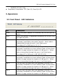
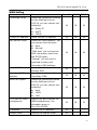
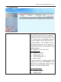
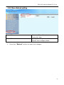
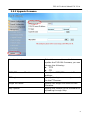
FXS-08
8-ports FXS VoIP Gateway
(SIP)
User Manual
Revision Information
Version
Date
Description
EN-V2.0a
2nd English Version
Apr-2-2008
FXS-08 Technical Manual EN-V2.0a
Table of Contents
1. Introduction ........................................................................................................................... 3
1.1 FXS-08 --8-ports Telephony Gateway .............................................................................. 3
1.2 Benefits: ............................................................................................................................... 3
1.3 Physical Interface: .............................................................................................................. 3
1.4 Specification:....................................................................................................................... 3
1.5 Setting and maintenance ................................................................................................... 5
1.6 Environmental...................................................................................................................... 5
2. Appearance ............................................................................................................................ 6
2.1 Front Panel: LED Indicators............................................................................................ 6
2.2 Rear Panel:........................................................................................................................... 8
3. Environment Setup and IP Connection.............................................................................. 9
3.1Configuration........................................................................................................................ 9
3.2 Network Configuration..................................................................................................... 11
3.2.1 WAN Setting ................................................................................................................... 11
3.2.1.1 WAN Setting --Static IP ......................................................................................... 14
3.2.1.2 WAN Setting --DHCP............................................................................................ 15
3.2.1.3 WAN Setting --PPPoE ........................................................................................... 15
3.2.2. LAN Setting.................................................................................................................... 16
3.3 General configuration....................................................................................................... 18
3.3.1 SIP Setting...................................................................................................................... 18
3.3.1.1 Proxy mode................................................................................................................. 18
3.3.1.2 Peer to Peer mode..................................................................................................... 21
3.3.2 SIP Advanced Setting.................................................................................................... 23
3.3.3 Payload Type Setting..................................................................................................... 26
3.3.4 Line Setting..................................................................................................................... 28
3.3.5 Qos Setting..................................................................................................................... 31
3.3.6 NAT Setting..................................................................................................................... 34
3.3.7 Speed Dial Setting ......................................................................................................... 35
3.3.7.1 Speed Dial.................................................................................................................... 35
3.3.7.2 Internal Extension ...................................................................................................... 36
3.3.7.2 Peer to Peer call.......................................................................................................... 37
3.3.8 Caller ID Setting ............................................................................................................ 38
3.3.9 CDR Setting .................................................................................................................... 40
3.3.10 Syslog Setting .............................................................................................................. 41
1
FXS-08 Technical Manual EN-V2.0a
3.4 Advanced Configuration................................................................................................... 42
3.4.1 System setting................................................................................................................ 42
3.4.2 SNTP Setting .................................................................................................................. 46
3.4.3 Codec Setting ................................................................................................................. 47
3.4.4 Voice Setting................................................................................................................... 49
3.4.5 Tone Setting ................................................................................................................... 51
3.4.6 Phone Setting................................................................................................................. 53
3.4.7 Digit Manipulation.......................................................................................................... 55
3.4.8 Dial Plan.......................................................................................................................... 57
3.5 Management ...................................................................................................................... 59
3.5.1 Provision Server ............................................................................................................. 59
3.5.2 Save-Reload setting....................................................................................................... 60
3.5.3 Upgrade Firmware......................................................................................................... 61
3.5.3.1 Updating the firmware by FTP................................................................................. 62
3.5.3.2 Updating the firmware by TFTP .............................................................................. 63
3.5.3 3 Updating the firmware by HTTP.............................................................................. 64
3.5.4 Reset to Default............................................................................................................. 65
3.5.5 Network Status .............................................................................................................. 66
3.5.6 Version Info.................................................................................................................... 67
3.5.7 Port Status ...................................................................................................................... 68
3.5.8 Password......................................................................................................................... 69
3.6 Rebooting the system ...................................................................................................... 70
2
FXS-08 Technical Manual EN-V2.0a
1. Introduction
1.1 FXS-08 --8-ports Telephony Gateway
The FXS-08 is an 8-ports FXS VoIP gateway to connect 8 analog phones (POTS)
and includes 1-WAN/4-LAN 10/100 base-T NAT router for diverse network
environment. Field-proven quality of Voice communication and Fax transmission
over IP broadband access network to makes FXS-08 to be an excellent solution
for various VoIP applications.
1.2 Benefits:
l Ideally suited for Enterprise use, rich-feature designed to inter-work with
IP-PBXs for small and middle enterprises.
l Carrier-grade features are supported and tested to be fully interoperable with
leading Soft-Switches.
l Provide CDR for call shop application.
l Superb device for apartment VoIP service.
1.3 Physical Interface:
l
l
l
l
l
Ethernet port (RJ-45, 10/100 base-T)
Ø 1-WAN port, for connect to router, ADSL modem (ATU-R), or switch hub
directly.
Ø 4-LAN port, for PC or other network devices connecting.
Telephony port (RJ-11)
Ø 8-FXS ports, to connect with analog phone (POTS)
Reset button (Factory Default)
AC power Jack
Status indicated LED
Indicates Ethernet, FXS, and SIP system status
1.4 Specification:
l
IP
Ø
Ø
Ø
Network connection
IPv4 (RFC 791)
MAC Address (IEEE 802.3)
PPPoE Client (RFC 2516)
3
FXS-08 Technical Manual EN-V2.0a
l
Ø
Ø
Ø
Ø
Ø
Ø
Ø
Ø
Ø
Ø
Ø
Ø
Ø
IP
Ø
DNS Client
DHCP Client (RFC 2131)
DHCP Server (RFC 2131)
NAT (RFC 1631)
TCP/UDP (RFC 793/768)
ICMP (RFC 792)
RTP/RTCP (RFC 1889/1890)
SNTP (RFC 2030)
TFTP Client
Telnet Server
HTTP Server
QoS – 802.1Q Virtual LANs
DiffServ (RFC 2475) / ToS (RFC 791/1349)
Telephony (VoIP)
SIPv2 (RFC 3261)
-
Session Timer (RFC 4028)
Privacy Mechanism (RFC 3323)
Outbound proxy setting for increasing performance, productivity,
and security.
Ø
SIP proxy redundancy- Setting Primary and Secondary proxy by IP or
URI.
Voice Codecs
Ø
Ø
Ø
Ø
Ø
Ø
Ø
Ø
G.711 (a-Law/u-Law): 64 bits (PCM)
G.723.1: 6.3k/5.3k bits
G.729A: 8k bits (CS-SCELP)
G.729B: adds VAD and CNG to G.729
VAD – Voice Activity Detection with Silence Suppression
CNG – Comfortable Noise Generation
Echo Cancellation (G.165/G.168)
Jitter Buffer – Adaptive & Configurable
Packet Loss compensation - increasing voice quality
DTMF: In-band, Out -of-band (RFC 2833), and SIP-Info
Caller Generation – FSK
FAX transmission
Ø
G.711 pass-through
T.38 Fax relay protocol
Tone Generation & Detection
-
-
Ringing Tone
4
FXS-08 Technical Manual EN-V2.0a
Ø
l
Ring Back Tone
Dial Tone
Programming Tone
Call Features
Call Hold
Call Transfer (Blind & consultant)
Call Forward (Unconditional / No Answer / Busy)
Call Conference (3-ways)
Ø MWI – Message Waiting Indication
Ø IP line hunting
Ø Adjustable volume level
Security
Ø HTTP 1.1 basic/digest authentication for WEB access
Ø MD5 for SIP authentication (RFC 2069/2617)
Ø Password protected Admin access authority
1.5 Setting and maintenance
l
Configure & Update method
l
l
l
Web Browser (HTTP)
Telnet
FTP/TFTP
Setting parameter Import /Export
Voice announcement of IP address
Syslog Client – Debug & CDR (Call Detail Record)
1.6 Environmental
l
Dimension: 35 ×242 ×160 mm (Desktop)
l
l
Weight: 0.935kg (unit)
Operating Temp. & Humidity
Temp.: 0℃∼45℃ (32℉∼113℉)
Humidity: 10%∼85% relative humidity, non-condensing
Storage Temp. & Humidity
Temp.: 0℃∼55℃ (32℉∼131℉)
Humidity: 10%∼95% relative humidity, non-condensing
AC Power Adaptor:
l
l
-
INPUT: AC100V-240V, 50/60Hz
5
FXS-08 Technical Manual EN-V2.0a
l
OUTPUT: DC 12V, 3.0A
Regulatory Compliance: FCC (Part 15, Class B) & CE
2. Appearance
2.1 Front Panel: LED Indicators
LED
Power
Description
When the power adapter is connected, the LED will light up
green.
Proxy
When the gateway is registered successfully to a Proxy, this
will light up green.
WAN
This will light up green when the gateway’s WAN port is
physically connected to the public internet. When data is
transmitted through this port, it will flash green.
The default IP of WAN port is 10.1.1.3.
This will light up green when the gateway’s LAN port 1 is
physically connected to a local network (Refer to Rear Panel
section in page number for location of LAN port 1). When
data is transmitted through this port, it will flash green.
The default IP of LAN port is 192.168.123.123.
LAN 1
LAN 2
This will light up green when the gateway’s LAN port 1 is
physically connected to a local network (Refer to Rear Panel
section in page number for location of LAN port 2). When
data is transmitted through this port, it will flash green.
LAN 3
This will light up green when the gateway’s LAN port 1 is
physically connected to a local network (Refer to Rear Panel
section in page number for location of LAN port 3). When
data is transmitted through this port, it will flash green.
This will light up green when the gateway’s LAN port 1 is
physically connected to a local network (Refer to Rear Panel
section in page number for location of LAN port 4). When
LAN 4
6
FXS-08 Technical Manual EN-V2.0a
T1
data is transmitted through this port, it will flash green.
The status LED for FXS port 1, this will light up amber orange
when the connected phone ’s handset is lifted, or when the
connected phone is engaged in a conversation. It will flash
amber orange when there is an incoming call.
T2
The status LED for FXS port 2, this will light up amber orange
when the connected phone ’s handset is lifted, or when the
connected phone is engaged in a conversation. It will flash
amber orange when there is an incoming call.
T3
The status LED for FXS port 3, this will light up amber orange
when the connected phone’s handset is lifted, or when the
connected phone is engaged in a conversation. It will flash
amber orange when there is an incoming call.
The status LED for FXS port 4, this will light up amber orange
when the connected phone ’s handset is lifted, or when the
connected phone is engaged in a conversation. It will flash
amber orange when there is an incoming call.
T4
T5
The status LED for FXS port 5, this will light up amber orange
when the connected phone ’s handset is lifted, or when the
connected phone is engaged in a conversation. It will flash
amber orange when there is an incoming call.
T6
The status LED for FXS port 6, this will light up amber orange
when the connected phone ’s handset is lifted, or when the
connected phone is engaged in a conversation. It will flash
amber orange when there is an incoming call.
The status LED for FXS port 7, this will light up amber orange
when the connected phone ’s handset is lifted, or when the
connected phone is engaged in a conversation. It will flash
amber orange when there is an incoming call.
T7
T8
The status LED for FXS port 8, this will light up amber orange
when the connected phone ’s handset is lifted, or when the
connected phone is engaged in a conversation. It will flash
amber orange when there is an incoming call.
7
FXS-08 Technical Manual EN-V2.0a
2.2 Rear Panel:
Item
Reset
Description
Press and hold over 5 seconds to reload factory default
setting, this will erase all the settings configured on the
gateway.
T8
The RJ-11 FXS port 8, connects analog phone sets, trunk line
or PABX.
T7
The RJ-11 FXS port 7, connects analog phone sets, trunk line
or PABX.
The RJ-11 FXS port 6, connects analog phone sets, trunk line
or PABX.
T6
T5
The RJ-11 FXS port 5, connects analog phone sets, trunk line
or PABX.
T4
The RJ-11 FXS port 4, connects analog phone sets, trunk line
or PABX.
The RJ-11 FXS port 3, connects analog phone sets, trunk line
or PABX.
T3
T2
The RJ-11 FXS port 2, connects analog phone sets, trunk line
or PABX.
T1
The RJ-11 FXS port 1, connects analog phone sets, trunk line
or PABX.
10/100 Base-T RJ-45 socket for LAN port 4, connects to local
area network.
LAN 4
LAN 3
10/100 Base-T RJ-45 socket for LAN port 3, connects to local
area network.
LAN 2
10/100 Base-T RJ-45 socket for LAN port 2, connects to local
area network.
10/100 Base-T RJ-45 socket for LAN port 1, connects to local
area network.
LAN 1
WAN
10/100 Base-T RJ-45 socket for WAN port, connects to wide
area network.
DC 12V
The power socket, input AC 100V~120V; output DC12V.
8
FXS-08 Technical Manual EN-V2.0a
3. Environment Setup and IP Connection
Please make sure that the network interface of your computer is working fine and
the cross over line (RJ-45) is connected to the computer correctly. You can also
connect your computer to the gateway using a hub.
The FXS-08 by default uses DHCP for its LAN port and assigns IP addresses to
clients connected to it, please make sure that your PC or Notebook’s network
configuration is set to DHCP.
3.1Configuration
Login to the FXS-08 web configuration menu
1. Get an Ethernet Cable to connect your PC and FXS-08 with LAN 1 port, then
change the Internet protocol (TCP/IP) of your PC with IP 192.168.123.X, X
can be 1~122.
2. Open your WEB browser and key in the IP address of the gateway
(http://192.168.123.123) in the Address box (see figure below).
9
FXS-08 Technical Manual EN-V2.0a
3. You will see a pop-up window requesting username and password before you
can login to the web configuration menu. Username is “root” while password is
blank “ “ (see figure below).
3. You will enter the main page of the web configuration interface after you
keyed in the username and password correctly (see figure below).
10
FXS-08 Technical Manual EN-V2.0a
3.2 Network Configuration
The following instructions will explain the configurations for setting up the WAN
port of the FXS-08. There are in total three methods of connections: Static IP,
DHCP and PPPoE.
Note: You can retrieve the IP address of the WAN port by keying #126# on the
phone set that is connected to the FXS port of the gateway. You will hear an IVR
announcing the current IP address of the WAN port.
3.2.1 WAN Setting
The table shown below describes the configuration items for 3 connection types
of network (Static IP, DHCP and PPPoE).
11
FXS-08 Technical Manual EN-V2.0a
WAN Setting
Item
Connected mode
Current IP Address
Description
Static IP
Select the connection method
for the WAN port of the
FXS-08, you can choose the
following:
V
l Static IP
l DHCP
l PPPoE
Show current IP address
Select the DNS behavior, you
can choose the following:
l Auto
l Manual
“DNS auto” will retrieve the
DNS information sent from
the DHCP server.
“Manual” will look at the
specified Primary and
Secondary DNS address.
Primary DNS address Specify the address of the
Primary DNS.
DHCP PPPoE
V
V
V
V
V
V
V
V
V
V
V
V
V
V
V
V
V
V
V
V
DNS server mode
Secondary DNS
address
Specify the address of the
Secondary DNS.
WAN Link Speed
Select the connection speed
for the WAN port of the
FXS-08, you can choose the
following:
l Auto
l 100M
l 10M
Specify the port number for
WEB management, the
allowable range is
80,1024~65535.
HTTP port for WEB
management
IP address
Specify the IP address.
V
Subnet mask
Specify the subnet mask.
V
12
FXS-08 Technical Manual EN-V2.0a
WAN Setting
Item
Default gateway
Description
Specify the IP address of the
default gateway.
Remote access
restriction
Restricts/Blocks users
connecting to the WAN port’s
IP remotely, you can
Enable/Disable this option.
PPPoE userID
Specify the username of the
PPPoE account
Specify the password
associated to the PPPoE
account above.
PPPoE password
Reboot after remote
host disconnection
When the remote host
(PPPoE) fails, the gateway
will retry 3 times to
reconnect, if there is no reply
from the remote host within 3
tries, then the gateway will
reboot. You can
Enable/Disable this option.
Static IP
DHCP PPPoE
V
V
V
V
V
V
V
13
FXS-08 Technical Manual EN-V2.0a
3.2.1.1 WAN Setting --Static IP
1.
Press the “Apply” button (at the bottom) after you finish to save changes.
2.
Press the “Reboot” button to apply the changes.
14
FXS-08 Technical Manual EN-V2.0a
3.2.1.2 WAN Setting --DHCP
1.
2.
Press the “Apply” button (at the bottom) after you finish to save changes.
Press the “Reboot” button to apply the changes.
3.2.1.3 WAN Setting --PPPoE
1.
2.
3.
Press the “Apply” button (at the bottom) after you finish to save changes.
Press the “CANCEL” button (next to the Apply button) to clear the values in
the page.
Press the “Reboot” button to apply the changes.
15
FXS-08 Technical Manual EN-V2.0a
3.2.2. LAN Setting
LAN Setting
ITEM
LAN IP address
Description
Specify the IP address of the FXS-08’s
LAN port.
LAN mask address
Specify the mask address for FXS-08’s
LAN port.
DHCP server
Enable/Disable DHCP function on
the LAN port. Once enabled, the LAN
ports will function as a DHCP server,
network devices connected to them
will be issued with IP addresses.
When DHCP is enabled, you can
specify the IP address to start from
when assigning to attached network
devices.
IP address from
IP address to
When DHCP is enabled, you can
specify the ending IP address assigned
to the attached network devices.
16
FXS-08 Technical Manual EN-V2.0a
LAN Setting
ITEM
Domain Name
Description
You can specify the domain name that
will be assigned by the DHCP server to
the attached network devices. The
DHCP server will send information on
the “server host name” to the DHCP
client.
Lease time(sec)
You can specify the maximum lease
time of the IP address allocated to the
DHCP client.
DNS server mode
Select the DNS behavior, you can
choose the following:
l Auto
l Manual
“DNS auto” will retrieve the DNS
information sent from the DHCP
server.
“Manual” will look at the specified
Primary and Secondary DNS address.
Specify the address of the Primary
DNS.
Primary DNS address
Secondary DNS address
1.
2.
Specify the address of the Secondary
DNS.
Press the “Apply” button (at the bottom) after you finish to save changes.
Press the “Reboot” button to apply the changes.
17
FXS-08 Technical Manual EN-V2.0a
3.3 General configuration
To make VoIP calls, you will need a SIP account provided by the SIP
Proxy you are registered with. To configure the relevant SIP settings,
please refer to the instructions explained below.
3.3.1 SIP Setting
3.3.1.1 Proxy mode
Primary proxy/P2P IP
Secondary proxy
Specify the data of primary proxy :
Enable/Disable, IP address, Port#,
Domain Name, Expire time and MWI
TTL.
The P2P mode will be explained in next
paragraph 3.3.1.2
Specify the data of secondary proxy:
Enable/Disable, IP address, Port#,
Domain Name, Expire time and MWI
TTL
Outbound proxy
Specify the data of Outbound proxy:
Enable/Disable, IP address and Port#.
Primary proxy Call Number
Configure the SIP account with
18
FXS-08 Technical Manual EN-V2.0a
configuration
Representative Number
Representative Number mode or
L1~L8 Separate Number mode, or the
Blending mode (Representative
Number & L1~L8 Separate Number
mode)
Input the relevant data for Enable line,
Register status, SIP Account, Number,
Password, and Display Name.
Note: If you use the representative
number to register, please check the
max. concurrent call of subscriber (the
representative number) in your SIP
proxy server or softswitch.
Line 1 ~ Line 8
Input the relevant data for Enable line,
Register status, SIP Account, Number,
Password, and Display Name.
Enable Line
Enable or disable the Line, the default
setting is “Enable”.
Note: If you disable the line, all the
registration and basic call for that line
will be disabled.
Register or Unregister to SIP Proxy
Register
Account
Input the SIP Proxy registration
account ID.
Number
Password
Input the phone number.
Input the password of IP Proxy
registration account ID.
Display name
Specify the Display name of the phone
number
1.
2.
Enter the IP address and port number of the SIP proxy into the Primary proxy
address and Port fields. Select the line you would like to configure the
account on in the Call line drop down list, and enter the relevant SIP account,
phone number and password. Once finished, press the “Apply” button to
save changes.
Press the “Reboot” button to apply the changes.
19
FXS-08 Technical Manual EN-V2.0a
If you Enable the Secondary proxy, system will display the “Secondary proxy call
Number Configuration” figure as shown below.
Secondary proxy Call Number
configuration
If you enable the secondary proxy,
System will display “Secondary
proxy Call Number configuration”
figure, Please refer to the description
of “Primary proxy Call Number
configuration” and fill the relevant
data.
20
FXS-08 Technical Manual EN-V2.0a
3.3.1.2 Peer to Peer mode
Peer A— FXS-08(for example the IP address is : 192.168.15.14)
Peer B— FXS-08(for example the IP address is: 192.168.15.62)
21
FXS-08 Technical Manual EN-V2.0a
Primary proxy/P2P IP
(Peer A/ Peer B)
Specify the destination IP Address of
Peer to Peer mode, and specify the
port# with 5076.
In this application, we define the
Peer to Peer mode in 2 groups. If
you want to make call to others IP
addresses, please refer to the
paragraph 3.3.7 Speed dial
setting.
Call number configuration
Representative number
(Peer A/ Peer B)
Disable and unregistered the
representative line
Line 1~Line 8
(Peer A/ Peer B)
Please refer to the figure shown above,
Enable all the line and Disable all
the register of two sides.
Specify the relevant data: Account,
number, password and display name.
1.
2.
Press the “Apply” button (at the bottom) after you finish to save changes.
Press the “Reboot” button to apply the changes.
22
FXS-08 Technical Manual EN-V2.0a
3.3.2 SIP Advanced Setting
Local SIP port (1~65535)
Local RTP port (1~65535)
Specify the local SIP port’s number.
Specify the local RTP port’s number.
Session Expire(Sec)
Specify the session expire time that
will be used to negotiate with the
remote host or proxy.
Min Session Expire(Sec)
Specify the minimum session expire
time that other host or proxy will need
to follow when calling the FXS-08.
Select the session refresh method that
will be used on the FXS-08, you can
choose among the two methods:
l UPDATE
l Re-Invite
Session Refresh Request
Session Refresher
Select who will perform the refreshes,
you can choose among the two
methods:
l UAC (Client)
l UAS (Server)
This will add the parameter
23
FXS-08 Technical Manual EN-V2.0a
Unregister All
refresher=uac or uas in the Session
Refresh Request message.
Send SIP unregister signaling message
after the FXS-08 has been restarted
Early media Treatment
Use early media treatment SIP
protocol, where SIP invite messages
will not include SDP.
Support SIP Ping
Special feature used with only
Nortel’s SIP proxy.
When this feature is Enabled, all IP
outgoing calls’ Caller ID will not be
displayed to the destination.(Please
make sure your proxy server or
softswitch supports the feature, if
the proxy does not support it and
you enable this feature, all IP
outgoing calls will be dropped.)
When Disabled, all IP out going calls’
Caller ID will be displayed to the
destination.
IP Anonymous Caller ID
Support SIP 'Allow' Header
When enabled, the FXS-08 will provide
information on what methods it
supports in the allow header. You can
choose to disable this option if you do
not want to provide this information.
Note: Some SIP proxy servers require
this feature, like Broadsoft SIP proxy,
when your facility connects to these
servers, please Enable it.
Support Message Waiting Indication
You can Enable or Disable the MWI
(MWI)
function.
SIP Message Resend Timer Base (sec) Specify the resend time in seconds for
each SIP request message that has not
received a response.
Max. Response Time for Invite
(1~30sec)
Specify the timeout period for SIP
Invite messages. For example, if the
timeout period is 10 seconds, when the
FXS-08 sends an Invite message and
24
FXS-08 Technical Manual EN-V2.0a
does not receive a response within 10
seconds, it will cancel the call.
1.
2.
Press the “Apply” button (at the bottom) after you finish to save changes.
Press the “Reboot” button to apply the changes.
25
FXS-08 Technical Manual EN-V2.0a
3.3.3 Payload Type Setting
RFC2833 payload type
T.38 FAX payload type
Specify the RFC2833 payload type
(range is 96~128, however 100,
102~105 is reserved by other payload
types).
Specify the FAX payload type (range is
96~128, however 100, 102~105 is
reserved by other payload types)
T.38 Redundancy payload type
Specify the Redundancy payload type
(range is 96~128, default value is 104.
100, 102, 103, 105 is reserved by
other payload types).
T.30 FAX by pass payload type
Specify the FAX by pass payload type
(range is 96~128, default value is 102.
100, 103~105 is reserved by other
payload types).
Specify the Modem by pass payload
type (range is 96~128, default value is
103. 100, 102, 104, 105 is reserved by
Modem by pass payload type
26
FXS-08 Technical Manual EN-V2.0a
Modem relay payload type
3.
4.
other payload types).
Specify the Modem relay payload type
(range is 96~128, default value is 105.
100, 102~104 is reserved by other
payload types).
Press the “Apply” button (at the bottom) after you finish to save changes.
Press the “Reboot” button to apply the changes.
27
FXS-08 Technical Manual EN-V2.0a
3.3.4 Line Setting
Representative Forward
Specify the Representative forwarding
type to use, you can choose the
following:
l Disable
l Unconditional
l Busy
28
FXS-08 Technical Manual EN-V2.0a
Representative Forward Number
No Answer Forward Time
Line1~Line8 relevant data
Type
l No Answer
The “Disable” option will allow you to
disable this particular function.
Specify the number to forward the call
to when the call forwarding feature is
enabled.
If you enable the No Answer Forward
function (Representative number or
L1~L8 number), please specify the
time of no answer. The default setting
is 30 sec.
Displays the port type of that
particular line.
Line Number
Displays the line numbers that
specified in SIP Setting.
The first is the number registers to
Primary proxy.
The second is the number registers to
Secondary proxy.
The default setting is 1000~1007.
Enable Hotline
Click the check box to enable hotline
feature. If enabled, The check box will
display as
.
Hotline Number
Specify the number to forward the call
to when the Hotline feature is enabled.
Wait to Hotline(sec)
Specify the time (sec) for wait to
hotline, the default value is 0.
Forward Type
Specify the forwarding type to use, you
can choose the following:
l Disable
l Unconditional
l Busy
l No Answer
The “Disable” option will allow you to
disable this particular function.
Specify the number to forward the call
Forward Number
29
FXS-08 Technical Manual EN-V2.0a
Reg.
to when the call forwarding feature is
enabled.
Displays the registration status,
whether it is registered or not.
Status
Displays the line status, whether it is
ready (Idle) or busy.
Call transfer
Enable/Disable per-line Call transfer
function.
Enable/Disable per-line Call Waiting
function.
Call Waiting
DND
Enable/Disable per-line DND (Do Not
Disturb) function.
FAX
Greeting(FXO only)
Enable/Disable per-line FAX function.
NA
Hot PSTN(FXO only)
NA
1.
2.
Press the “Apply” button (at the bottom) after you finish to save changes.
Press the “Reboot” button to apply the changes.
30
FXS-08 Technical Manual EN-V2.0a
3.3.5 Qos Setting
Type
Select Qos Type: DSCP or ToS
Differentiated Services Code Point Setting (DSCP)
DSCP RTP
Select the DSCP value for RTP (voice
packets), the value in the drop down
list is expressed in binary format, you
can choose the following:
l 0
l 10
l 12
l 14
l 18
l 20
l 22
l 26
l 28
l 30
l 34
l 36
l 38
l 46
31
FXS-08 Technical Manual EN-V2.0a
DSCP Signal
Select the DSCP value for SIP
message, the value in the drop down
list is expressed in binary format, you
can choose the following:
l 0
l 10
l 12
l 14
l 18
l 20
l 22
l 26
l 28
l 30
l 34
l 36
l 38
l 46
ToS Setting
ToS RTP
Select the ToS value for RTP (voice
packets), the value in the drop down
list is expressed in binary format, you
can choose the following:
l 000
l 001
l 010
l 011
l 100
l 101
l 110
l 111
ToS Signal
Select the ToS value for SIP messages,
the value in the drop down list is
expressed in binary format, you can
choose the following:
l 000
32
FXS-08 Technical Manual EN-V2.0a
l
l
l
l
l
l
l
1.
2.
001
010
011
100
101
110
111
Press the “Apply” button (at the bottom) after you finish to save changes.
Press the “Reboot” button to apply the changes.
33
FXS-08 Technical Manual EN-V2.0a
3.3.6 NAT Setting
IPSharing Mode
IPSharing Address
1.
2.
Select IPSharing mode : Enable or
Disable
Specify the IPSharing Address when
the IPSharing feature is enabled.
Press the “Apply” button (at the bottom) after you finish to save changes.
Press the “Reboot” button to apply the changes.
34
FXS-08 Technical Manual EN-V2.0a
3.3.7 Speed Dial Setting
3.3.7.1 Speed Dial
Speed Dial Editor
Specify the speed Dial
Number/Telephone Number/Name,
then press the Add or Del button to
add or delete record
35
FXS-08 Technical Manual EN-V2.0a
3.3.7.2 Internal Extension
Note: The speed dial function can be used as Internal Extension when
the Ethernet is fail. For example :
1. When the FXS-08’s IP is fixed IP 192.168.123.1, you can set the
speed dial as the figure shown above (please be informed that
the speed dial number should be the same with SIP setting
number and the format of “Telephone Number” is “#@ipaddress”
for example [email protected]), in the meantime, the WAN port
is disconnected, and you can use it as internal extension.
2. When the FXS-08’s IP is operating in DHCP client mode, you can also
set the speed dial as figure 1, internal calls can work when the
Ethernet is fail. But if you make power reset of the device when it
has no WAN connection, the speed dial function (internal extension)
will not work because it cannot get an IP address from a DHCP
server.
36
FXS-08 Technical Manual EN-V2.0a
3.3.7.2 Peer to Peer call
Speed Dial Editor
(In P2P application)
Specify the speed Dial
Number/Telephone Number/Name,
then press the Add or Del button to
add or delete record
The format of “Telephone Number” is
“#@ipaddress”, for example
[email protected]
37
FXS-08 Technical Manual EN-V2.0a
3.3.8 Caller ID Setting
Caller ID Setting (Line 1~Line 8)
Select the (Line 1~Line 8)Caller ID
generation type to use, you can choose
the following:
l Disable
l DTMF
l FSK(Bellcore)
l ETSI(Before Ring)
l ETSI(Between ring)
AUTO: You can choose different caller
ID type by line. If Line1~Line 8 uses
the same type, you only need to set
line 1 and click the “Auto” button, then
the other lines will set the same type
automatically.
The “Disable” option will allow you to
disable this particular function.
38
FXS-08 Technical Manual EN-V2.0a
DTMF Caller ID Start Symbol
DTMF Caller ID End Symbol
1.
2.
Specify the DTMF Caller ID Start
Symbol
The default symbol is D.
Specify the DTMF Caller ID End Symbol
The default symbol is C.
Press the “Apply” button (at the bottom) after you finish to save changes.
Press the “Reboot” button to apply the changes.
39
FXS-08 Technical Manual EN-V2.0a
3.3.9 CDR Setting
CDR mode
CDR Server address
CDR Server port
1.
2.
Select the CDR mode for Enable or
Disable. If you Enable this feature,
please specify the CDR Server address
and port number at the CDR server
address and port’s text box, then you
can get Call Detail Data form CDR
Server.
If you Enable the CDR mode, please
specify the IP address of CDR Sever for
data storage.
Specify the CDR Server port number,
The default port number is 514.
Press the “Apply” button (at the bottom) after you finish to save changes.
Press the “Reboot” button to apply the changes.
40
FXS-08 Technical Manual EN-V2.0a
3.3.10 Syslog Setting
Syslog mode
Syslog Server address
Syslog Server port
1.
2.
Select the Syslog mode for Enable or
Disable. If you Enable this feature,
please specify the Syslog Server
address and port number at the Syslog
server address and port ’s text box,
then you can get detail system log
from Syslog server.
If you Enable the Syslog mode, please
specify the IP address of Syslog Sever
for data storage.
Specify the Syslog Server port number,
The default port number is 514.
Press the “Apply” button (at the bottom) after you finish to save changes.
Press the “Reboot” button to apply the changes.
41
FXS-08 Technical Manual EN-V2.0a
3.4 Advanced Configuration
3.4.1 System setting
prack
ROH
PRACK is defined in RFC 3262:
Reliability of Provisional Responses in
SIP. You can accommodate your
softswitch (Proxy Server) to Enable or
Disable this feature.
Receiver-Off-Hook (ROH) Tone
A ROH tone is sent to the subscriber to
inform him that his receiver is
off-hook.
You can Enable/Disable this option.
Send billing signal
Polarity Reversal for billing signal, you
can enable (Reverse)/Disable the
feature.
T.38 NoAttribute
No attribute (Fax version, BitRate,
Buffer, Datagram… ) indicated in T.38
Re-Invite with Session Description
42
FXS-08 Technical Manual EN-V2.0a
FAX redundancy depth
Protocol (SDP).
You can Enable/Disable this option.
Specify the resend times (0~3)for FAX
error packet,
T.38 FAX Type
Select the FAX Type to use, you can
choose the following:
l
T.38
l
ByPass
l
Auto
T.30 FAXByPass Codec
Select the FAX ByPass Codec to use,
you can choose the following:
l
G.711 a-law
l
G.711 u-law
l
G.726 32k
Select the function of Flash key, you
can choose the following:
l
Disable
l
Transfer
l
SIP Message
Flash key function
Keypad DTMF type
Select the type of Keypad DTMF, you
can choose the following:
l
In-Band
l
RFC2833
l
SIP Info
End of dial key
Select the End of dial key, you can
choose the following:
l
Disable
l
*
l
#
Specify the grade of DTMF Detection
Sensitivity, the value range is (1~5)
DTMF Detection Sensitivity
Dial Wait Timeout (1~60sec)
Specify the duration of dial waiting
when the receiver is off hook. The
range is 1~60 sec.
Inter Digits Timeout (1~5sec)
Specify the interval of input digits, if
the interval is over the setting, the
system will end the dial and send out
the DTMF. The limitation range is
43
FXS-08 Technical Manual EN-V2.0a
FAXByPass Keyword
1~5sec.
Some SIP Proxy need specify special
keyword for FAXByPass function. Input
the data as SIP Proxy required.
FAXByPass Keyword
Some SIP Proxy need specify special
keyword for FAXByPass function. Input
the data as SIP Proxy required.
IP Address announcement
You can Enable/Disable this function,
If you select Enable, you can connect
T1 port with a phone set and press
#120#, you will hear the
announcement of IP address of LAN
port, or press #126# to get WAN port
IP address.
System built-in music of call hold, you
can Enable/Disable this feature.
Built-in Call Hold Music
DTMF Duration
Specify the DTMF tone duration.
DTMF Interdigit Time
Ring Time Limit ( 10~600sec )
Specify the interval of DTMF digit
Specify the limitation of Ring time for
incoming call, when the ring is over the
limit, system will drop the call. The
default range is 10~600sec.
Loop Current Drop Duration
(0:disabl e, 100~1000ms )
Specify the duration (100~1000ms) of
loop current drop, 0 for disable. This
feature is used when the FXS-08 is
connected with answering machines.
When the remote site disconnects, the
system will drop FXS port ’s voltage to
0, and make the answering machines
disconnect.
FXS Voltage Drop
This option is used when a stand alone
relay box containing a PSTN and FXS
port is connected to the FXS-08’s FXS
port. In this special application, if
there is a network or registration
failure, the system will drop the FXS
port’s voltage to 0, when the relay box
detects the status, it will switch the
44
FXS-08 Technical Manual EN-V2.0a
ping ip to keep alive network
ping timer(sec)
1.
2.
line to PSTN.
The default setting is “Disable”, if you
are not using this particular special
application mentioned above, please
do not enable this function.
Specify the IP for pinging to make sure
the network keeps alive.
Specify the interval of ping timer(sec)
Press the “Apply” button (at the bottom) after you finish to save changes.
Press the “Reboot” button to apply the changes.
45
FXS-08 Technical Manual EN-V2.0a
3.4.2 SNTP Setting
SNTP mode
SNTP server address
Select the SNTP mode : On or Off
Specify the SNTP server address for
time synchronization.
Time Zone -GMT
Select the Time Zone of your location
Time setting
You can specify the time with
year/month/date /hour/minute
/second when you select the SNTP
mode with “Off”.
1.
2.
Press the “Apply” button (at the bottom) after you finish to save changes.
Press the “Reboot” button to apply the changes.
46
FXS-08 Technical Manual EN-V2.0a
3.4.3 Codec Setting
Codec Priority
Codec Packet Size
You can specify the priority of the
codec from First to Fifth (first being the
highest priority and Fifth being the
lowest). You can choose the following
codecs:
l G711U
l G711A
l G723
l G729
l G726
You can specify the packet size in the
drop down list for each particular
codec, you can choose the following:
G711U 10,20,30,40,50,60
G711A 10,20,30,40,50,60
Bandwidth Required
G723
G729
30,60,90
10,20,30,40,50,60
G726
10,20,30,40,50,60
When you select the codec packet size
47
FXS-08 Technical Manual EN-V2.0a
shown above, system will set default
requirement of bandwidth.
1.
2.
Press the “Apply” button (at the bottom) after you finish to save changes.
Press the “Reboot” button to apply the changes.
48
FXS-08 Technical Manual EN-V2.0a
3.4.4 Voice Setting
Jitter Buffer
Minimal Delay
Specify the minimal delay of the jitter
buffer. The range is 0~150 ms and the
default setting is 0 ms.
Maximal Delay
Specify the maximal delay of the jitter
buffer. The range is 0~200 ms and the
default setting is 200 ms.
OPTFactor
Specify the dynamic jitter buffer frame
error/delay optimization factor, the
range is 0~13.
Enable/Disable the VAD (Voice Activity
Detection) feature. This is supported
on all codecs that the FXS-08 equips.
VAD
Echo cancellation
Enable/Disable the echo cancellation
feature. The default setting is
“Enable”.
Local voice volume
Specify the volume gain of the voice in
the local side (0~63, default is 32).
You can set this option for each of the 8
49
FXS-08 Technical Manual EN-V2.0a
Remote receive volume
DTMF volume
1.
2.
lines.
Specify the volume gain of the voice in
the remote side (0~63, default is 32).
You can set this option for each of the 8
lines.
Specify the volume gain of the DTMF
(0~63, default is 27). You can set this
option for each of the 8 lines.
Press the “Apply” button (at the bottom) after you finish to save changes.
Press the “Reboot” button to apply the changes.
50
FXS-08 Technical Manual EN-V2.0a
3.4.5 Tone Setting
Dial tone
Ringback tone
Specify the pattern of the Dial tone,
you can adjust the high frequency, low
frequency, high level, low l evel, the On
and Off time for tone 1 and 2.
Specify the pattern of the Ringback
tone, you can adjust the high
frequency, low frequency, high level,
low level, the On and Off time for tone
1 and 2.
Busy tone
Specify the pattern of the Busy tone,
you can adjust the high frequency, low
frequency, high level, low level, the On
and Off time for tone 1 and 2.
Call-waiting
Specify the pattern of the call-waiting
tone, you can adjust the high
frequency, low frequency, high level,
low level, the On and Off time for tone
1 and 2.
Specify the pattern of the Voice-Notify,
you can adjust the high frequency, low
Voice-Notify
51
FXS-08 Technical Manual EN-V2.0a
ROH Tone
frequency, high level, low level, the On
and Off time for tone 1 and 2.
Specify the pattern of the ROH Tone,
you can adjust the high frequency, low
frequency, high level, low level, the On
and Off time for tone 1 and 2. The
ROH tone is a single high frequency
tone used to warn users that their
phone is not placed on-hook (hang up)
correctly.
Disconnect tone 1
Specify the pattern of the disconnect
tone for disconnect tone 1 (first set),
you can adjust the high frequency, low
frequency, high level, low level, the On
and Off time for tone 1 and 2.
Disconnect tone 2
Specify the pattern of the disconnect
tone for disconnect tone 2 (second
set), you can adjust the high
frequency, low frequency, high level,
low level, the On and Off time for tone
1 and 2.
1.
2.
Press the “Apply” button (at the bottom) after you finish to save changes.
Press the “Reboot” button to apply the changes.
52
FXS-08 Technical Manual EN-V2.0a
3.4.6 Phone Setting
Primary Ringing
Ringing Frequency
Specify the Ringing frequency value.
ringing frequency : 15~100 (Unit : Hz)
Ringing ON
Specify the Ringing ON value .
ringing ring ON : 0~8000 (Unit : ms)
Ringing OFF
Specify the Ringing OFF value.
ringing ring OFF : 0~8000 (Unit : ms)
Specify the ringing level.
ringing level : 0 ~ 94
(Unit : V)
Ringing level
Flash low
Specify the value of the flash (low).
: 60~2000 (Unit : ms)
Flash high
Specify the value of the flash (high).
: 60~2000 (Unit : ms)
Secondary Ringing
Note: The feature will be enable d automatically when the Min. Digit
Count has been enabled and specified.
Ringing Frequency
Specify the Ringing frequency value.
ringing frequency : 15~100 (Unit : Hz)
53
FXS-08 Technical Manual EN-V2.0a
Ringing ON
Ringing OFF
Specify the Ringing ON value.
ringing ring ON : 0~8000 (Unit : ms)
Specify the Ringing OFF value.
ringing ring OFF : 0~8000 (Unit : ms)
Ringing level
Specify the ringing level.
ringing level : 0 ~ 94
(Unit : V)
Min. Digit Count
Specify the minimum digit count
(1~10, 0:Disable), this feature is used
to change the ringing frequency by
detecting the digit length of incoming
calls’ number. When the digit length
of an incoming call number is greater
than the specified setting, the system
will use primary ringing. If the digit is
less than the specified setting, the
system will use the secondary ringing.
Specify the ringing standard to use.
Country
Phone setting— Representative number
Ring Type
Ring Time (s) for Serial ring
Priority
1.
2.
Select the Ring Type of representative
number. You can choose the following:
l Serial ring (Follow the ring priority
defined below)
l Simultaneous(ring all)
Specify the Ring Time for Serial ring
Select the group of representative
number, and specify the priority.
The default setting L1~L8 is grouped.
Press the “Apply” button (at the bottom) after you finish to save changes.
Press the “Reboot” button to apply the changes.
54
FXS-08 Technical Manual EN-V2.0a
3.4.7 Digit Manipulation
Digit Manipulation Testing
FXO Dial Pause
Digit Manipulation Editor
This option allows users to test dial a
number and check the resulting dialed
number and its routing path that is
edited by the Digit Manipulation Editor
function (see Digit Manipulation Editor
section below for more information on
it).
N/A
With this option, you can specify
whether to add digits to a prefix
number or drop a prefix number, and
its destination route depending on the
prefix of the number dialed.
For example, if the user sets:
First Example
l Prefix: 02
l Drop: Enable
l Insert:
l Route: VOIP
If the user dials 0282265699, the
resulting dial out number will be
82265699.
55
FXS-08 Technical Manual EN-V2.0a
Second Example
l Prefix: 7
l Drop: Disable
l Insert: 886
l Route: VOIP
If the user dials 778, the resulting dial
out number will be 886778.
Third Example (Only applicable for
WG2680 FXO)
l Prefix: 8226
l Drop: Disable
l Insert: 02
l Route: PSTN (Only applicable to
WG2680 FXO)
If the user dials 82265699, the
resulting dial out number will be
0282265699 with a destination route
to PSTN. In other words, the number
0282265699 will be dialed out to the
PSTN line from the WG2680 (FXO).
You can configure up to 50 entries in
the Digit Manipulation Editor.
Note: Destination route to PSTN and
DENY is only available on the WG2680
FXO).
1.
2.
Press the “Apply” button (at the bottom) after you finish to save changes.
Press the “Reboot” button to apply the changes.
56
FXS-08 Technical Manual EN-V2.0a
3.4.8 Dial Plan
Dial Plan Editor
Using this feature, users can specify
the number that will be immediately
dialed out without having to press the
“#” (at the end of the dialed number)
on the keypad or until the dial time
timeout period. The number can be
specified depending on the length of
the dialed number, or the prefix of the
dialed number.
For example, if the user sets:
First Example
l Function: Enable
l Leading digit: 02
l Total Digit count: 10
l Route: VOIP
If the user dials a 10 digit number with
a prefix of 02 (e.g. 0282265699), the
FXS-08 will immediately detect it and
dial this number straight away.
Second Example
l Function: Enable
l Leading digit:
57
FXS-08 Technical Manual EN-V2.0a
l Total digit count: 8
l Route: VOIP
If the user dials an 8 digit number (e.g.
82265699), the FXS-08 will
immediately detect it and dial this
number straight away.
Third Example
l Function: Disable
l Leading digit: 02
l Total digit count: 10
l Route: VOIP
If the user set the Function parameter
as “Disable”, the call number with a
length of 10 digits and a prefix of 02
will proceed as normal. The user will
need to wait until dial timeout period
for the call to be made, or press the
“#” on the keypad at the end of the
dialing number to make the call.
Fourth Example (Only applicable
for WG2680 FXO)
l Function: Enable
l Leading digit: 7
l Total digit count: 5
l Route: PSTN
If the user dials a 5 digit number with a
prefix of 7 (e.g. 76543), the WG2680
(FXO) will immediately detect it and
dial this number to PSTN.
You can configure up to 50 entries in
the Dial Plan.
Note: Destination route to PSTN and
DENY is only available on the WG2680
FXO).
1.
2.
Press the “Apply” button (at the bottom) after you finish to save changes.
Press the “Reboot” button to apply the changes.
58
FXS-08 Technical Manual EN-V2.0a
3.5 Management
3.5.1 Provision Server
Note: The provision function is only compatible with some proprietary provision
server. If you need this requirement, please contact with your agent.
Provision server Mode
Provision server IP address
Enable/Disable provision function
Specify the Provision Server’s IP
address.
Provision server port
Specify the Provision server port
Provision cycle time
Specify the cycle time of the
provisioning.(unit: sec)
Specify a scheduled time in a day
Provision default time
1.
2.
Press the “Apply” button (at the bottom) after you finish to save changes.
Press the “Reboot” button to apply the changes.
59
FXS-08 Technical Manual EN-V2.0a
3.5.2 Save-Reload setting
Export File
Import File
1.
Click the “Export ” button to export
“user.cfg” data
Specify the file path and file name to
Import the configure data.
Press the “Reboot” button to apply the changes.
60
FXS-08 Technical Manual EN-V2.0a
3.5.3 Upgrade Firmware
Download mode
TFTP/FTP server IP address
Select the connection method to
update the FXS-08’s firmware, you can
choose the following:
l TFTP
l FTP
Specify the TFTP/FTP server’s IP
address.
FTP login
Specify the login username/password
for the FTP server.
Target file name
Specify the target file name for the
firmware.
Specify the location of the firmware for
uploading through Http.
Http Upload
61
FXS-08 Technical Manual EN-V2.0a
3.5.3.1 Updating the firmware by FTP
1. Select FTP mode in the drop down list.
2. Key in the IP address, login name, password of your FTP server and specify
the correct filename of the firmware.
3. Press the Start button (next to the Target file name text box) to execute the
upgrade process.
4. Please wait while the device updates itself with the firmware.
5. After the update process is finish, you will be taken to a web page indicating
that it was successful (see figure below).
6. Press the “Reboot” button to apply the changes.
62
FXS-08 Technical Manual EN-V2.0a
3.5.3.2 Updating the firmware by TFTP
1. First, download the TFTP program from our website
http://www.welltech.com/support/utility.htm. Unzip the TFTP to a directory
that you desire in your hard drive and execute the TFTP program. Make sure
that the TFTP program points to the directory of where your firmware is
stored. Now, leave the TFTP program running and switch back to the FXS-08
web configuration interface.
2. Under Device Management => Software Upgrade select TFTP mode in the
drop down list.
3. Key in the IP address of the TFTP server and specify the correct filename of
the firmware.
4. Press the Start button (next to the Target file name text box) to execute the
upgrade process.
5. Please wait while the device updates itself with the firmware.
6. After the update process is finish, you will be taken to a web page indicating
that it was successful (see figure below).
7. Press the “Reboot” button to apply the changes.
63
FXS-08 Technical Manual EN-V2.0a
3.5.3 3 Updating the firmware by HTTP
1.
2.
3.
4.
5.
6.
7.
Under Device Management => Software Upgrade web menu, specify the
location of the firmware by clicking the Browse button next to the Http Upload
text box.
You will be prompted with a window requesting the location of the firmware.
Locate the firmware that is stored in your hard drive.
Once located, click the Open button.
Back in the web configuration menu, press the Start button (next to the Http
Upload’s browse button) to execute the upgrade process.
Please wait while the device updates itself with the firmware.
After the update process is finish, you will be taken to a web page indicating
that it was successful (see figure below).
Note: For consistency, it is recommended to reload default setting every time
you update the firmware on the FXS-08. However, you will lose all the settings
configured on the FXS-08 except Network configuration. For more details on
reload default setting, please refer to the next page below.
64
FXS-08 Technical Manual EN-V2.0a
3.5.4 Reset to Default
Users can restore back to factory default settings using this feature. The
password of the account and the network configurations are the things that will
not be changed when this feature is executed.
65
FXS-08 Technical Manual EN-V2.0a
3.5.5 Network Status
Connection mode
Current IP address
Displays the current connection mode.
Displays the current IP address of the
WAN port.
Subnet mask
Displays the current subnet mask’s IP.
Default gateway
Displays the current default gateway’s
IP.
Displays the current primary DNS
address.
Primary DNS address
Second DNS address
Displays the current secondary DNS
address.
WAN MAC
Displays the MAC address of the WAN
port.
66
FXS-08 Technical Manual EN-V2.0a
3.5.6 Version Info.
Boot version
Post version
Application version
Displays the current boot version
loaded on the FXS-08.
Displays the current post version
loaded on the FXS-08.
Displays the current application
version loaded on the FXS-08.
67
FXS-08 Technical Manual EN-V2.0a
3.5.7 Port Status
Item
Status
Displays the corresponding port
number.
Displays the status of the port.
Port Type
Displays the port type (FXS,FXO)of the
corresponding port number.
Register
Displays the registration status of the
corresponding port number.
68
FXS-08 Technical Manual EN-V2.0a
3.5.8 Password
Username
Current password
Select the type of user name that you
would like to configure the password
for, you can choose the following:
l root
l user
Specify the current password for the
user selected in the drop down list
above.
New password
Specify the new password for the user
selected in the drop down list above.
Confirm new password
Repeat the new password again for
confirmation.
1.
2.
Press the “Apply” button (at the bottom) after you finish to save changes.
Press the “Reboot” button to apply the changes.
69
FXS-08 Technical Manual EN-V2.0a
3.6 Rebooting the system
Executing this function will reboot the whole system, when configuration changes
are made to the device, it needs to be rebooted for the changes to take effect
(see figure below).
70