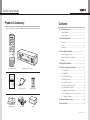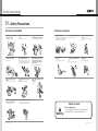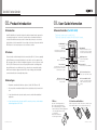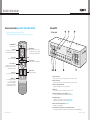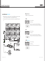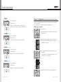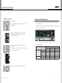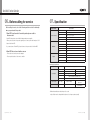
1
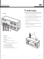
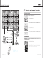
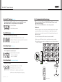
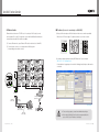
New Multi Function Controller ON OFF ID SETTING 1 2 3 4 5 6 7 SET 8 BROADCAST ON 9 OFF DVI 1 DVI 2 0 A B ORION CO., LTD. INFO www.oriondisplay.net DVI VIDEO Address: 257-6, Gongdan-dong, Gumi-si, Gyeongsangbuk-do, Korea Tel : +82-2-6678-8533, Fax: +82-2-6678-8599 INPUT SELECT PC DTV S-VIDEO HDSDI DVIC1 DVIC2 OUTPUT HDMI INFO AUTO FUNCTION REMOTE CONTROL • 2012.02.24 User's Manual Thank you for purchasing our New Multi Function Controller. Please read through this user's manual for safety before installing this product. This product is manufactured for Multi Plasma display model only. New Multi Function Controller Product & Accessary Contents Please check remote controller and all the accessories are included in the box 01. Safety Precautions.............................................................2 Cautions for New MFC......................................................................2 ON ID SETTING 1 2 3 4 5 6 7 8 9 BROADCAST ON 02. Product Introduction.........................................................4 OFF Introduction.....................................................................................4 DVI 1 DVI 2 0 SET Cautions for Adapter........................................................................3 OFF Features..........................................................................................4 A B Advantages ....................................................................................4 INFO DVI 03. User Guide Information....................................................5 DVI CONVERTER INPUT VIDEO PC DTV S-VIDEO HDSDI DVIC1 DVIC2 OUTPUT HDMI Remote Controller (For MFC-4250)........................................................5 INFO AUTO FUNCTION Remote Controller (For MFC-4260, MFC-MLCD)........................................6 MPDP New MFC........................................................................................7 PDP REMOTE CONTROL 04. New MFC Installation........................................................9 Remote Controller : 1EA Multi Function Controller : 1EA 05. How to use Remote Controller....................................11 05-1. Power ON/OFF .....................................................................11 05-2. BROADCAST .......................................................................11 05-3. AUTO Tracking (MFC-4250) .....................................................12 05-4. DVI Selector (MFC-4250) .........................................................12 05-5. Model Select (MFC-4260) .......................................................12 05-6. Mode Select (MFC-4260, MFC-MLCD) ........................................12 Manual : 1EA RS-232C Cable : 1EA Battery (AAA) : 2EA 05-7. Communication Mode change...............................................13 05-8. Input Selection (MFC-4260, MFC-MLCD) ....................................23 05-9. X x Y Configuration (e.g. Horizontal 5 sets x Vertical 6 sets)................27 05-10. Baud-Rate Configuration.....................................................29 06. Before calling for service...............................................30 07. Specification......................................................................31 L-Bracket : 2EA Adapter 1EA box 1EA ORION CO., LTD. | 1 New Multi Function Controller 01. Safety Precautions Cautions for New MFC Cautions for Adapter Please do not use at the places of hot and humid environment. Do not touch the power cable with wet hands. Do not store or use flammables like a combustible spray around the product. Use the provided adapter Do not put the product under the direct sunlight or near to hot places. Do not disassemble, repair or alter the product with users' own intention. If you detect smoke, smell or strange sound from the product, stop using the product immediately, disconnect the power cable and contact with an authorized service center. Do not put a heavy object on the cable or fold the cable. - It may damage the product. - It may cause fire. - It may cause an electric shock. - It may cause an electric shock or fire. If you need to test, adjust or repair the product, contact with an authorized service center. Do not spray water directly on the product. Carefully move the product not to give any shock. Please be careful not to soak unknown material or liquid into the product. Please keep away from children's reach. - It may cause an electric shock or fire. - It may damage the product. - It may cause product malfunction. - It has a possible danger of explosion or fire. - Improper adapters may damage the product. If you cannot use the provided adapter, use the adapter of proper specification. - It may cause an electric shock or fire. Do not touch the adapter with wet hands. - It may cause an electric shock. Do not connect to a multi-power-socket together with many other electric products. - It may cause an electric shock or fire. Make sure the power plug is properly connected. - Loose connection may cause an electric shock. Disconnect the power plug on the occasion of lightning. - It may damage the product. - It may cause an electric shock or fire. Please do not stack heavy objects on top of the product. - It may damage the product. - If they drop Remote Controller, it may hurt the children or cause product malfunction. Notice to users Class A digital device Warning 2 | ORION CO., LTD. It is a device designed for business purpose with a safety certificate for electromagnetic interference, which user should be mindful of. ORION CO., LTD. | 3 New Multi Function Controller 02. Product Introduction 03. User Guide Information Introduction Remote Controller (For MFC-4250) New MFC (Multi Function Controller) is designed for functional expansion and compensation in communication and users’ convenience. It provides various communicational interfaces of Serial, USB and Ethernet and also provides 4-channel daisy chain port to solve the most critical problem of serial communication. Users can find out the status of the product with the LED indicators. It is also functioning as a receiver for Remote-controller. * This Remote Controller is only for the MFC-4250. * This Remote Controller can control the OPM-4250 and DVI-Converter. ON POWER ON/OFF ID Setting Product is mainly controlled through the Serial communication (RS-232C). However, gradually, USB and Ethernet port are replacing Serial port in control devices such as computers. New MFC can support either case. Based on installation circumstance or Users’ preference, Serial (RS-232), USB or Ethernet can be selected. Especially, Ethernet allows controlling product through LAN network or even with Internet. Users can have better communication quality with 4-channel serial port equipped in a New MFC. It helps avoiding possible undesirable communicational distortion from multiple daisy-chains. Set the number of product in horizontal and vertical positions. (XxY) X x Y Setting Enter X x Y setting mode. ID SETTING Features 1 2 3 4 5 6 7 8 9 SET BROADCAST ON DVI MPDP Input select Function A / B Enter to the test mode of New MFC INPUT SELECT PC DTV S-VIDEO HDSDI DVIC1 DVIC2 OUTPUT HDMI INFO AUTO FUNCTION 1. Expand the communicational functions of product. (Serial / USB / Ethernet / IR) 2. Prevent possible communicational distortion from using Serial port by 4-channel serial port. Broadcast is the function to control all product sets at once. It is applied for Power On/Off and Auto tracking. B INFO Select directions to set the number of product (horizontal or vertical) and check the status of product. DVI Converter Output DVI 1 BROADCAST Select DVI input of MPDP, DVI 1 or DVI 2. A Select DVI Converter output, DVIC1 or DVIC2. OFF DVI 2 0 Direct & Info key VIDEO Advantages OFF Turn on/off product. DVI Converter Input Select Select source input for DVI converter. DVI Converter INFO / AUTO Check the current status information of DVI converter and execute Auto tracking. REMOTE CONTROL 3. Control the main functions of product and by a remote controller without additional applications. ※※ Control the main functions of product and DVI converter by a remote controller without additional applications. (MFC-4250) 4 | ORION CO., LTD. 1.Note : 2.How to mount batteries Use two 1.5V AAA-type batteries. Do not mix old and new batteries, Do not mix different types or makes of batteries. Mixed use of Alkaline, Manganese or Re-chargeable batteries are NOT recommended. Only use two batteries of the same type and make. Slide the cap at the rear side of the remote controller to open. Insert batteries with the correct polarity and close the cap. ORION CO., LTD. | 5 New Multi Function Controller Remote Controller (For MFC-4260, MFC-MLCD) * This Remote Controller is only for the MFC-4260. * This Remote Controller can control the OPM-4260, MLCD and e-Board. ON POWER ON/OFF 1 ID Setting 2 3 ID SETTING 4 5 6 7 8 9 X x Y Setting Enter X x Y setting mode. SET BROADCAST ON OFF MODE Select F1 - 1:1 Individual Screen Mode F2 - Full Screen Mode F3 - Return X x Y configuration setting to the previous status. F4 - Auto tracking for PC Input. BROADCAST Broadcast is the function to control all product sets at once. It is applied for Power On/Off and Auto tracking. Enter to the test mode of New MFC INFO INPUT SELECT DVI Input Select G Function A / B B Direct & Info key Select source input for product. E 0 A Select directions to set the number of product (horizontal or vertical) and check the status of product. D 1.Front side OFF Turn on/off product. Set the number of product in horizontal and vertical positions. (XxY) New MFC PC E-BOARD 117" VIDEO F1 84" MODEL SELECT F2 F3 MODE SELECT F4 Model Select A B C F H Select e-Board Model. A.Power On Indicator It is turned on when "Power-On" command is received from the remote-controller. B.Power Off Indicator It is turned on when "Power-Off" command is received from the remote-controller. C.Product configuration Indicator REMOTE CONTROL It indicates the configuration of "X x Y" in the 7-segments. D.IR Receiver It is the reception position for the IR signal from the remote-Controller. E.Indicator for DVI Input selection of MPDP (MFC-4250) It is turned on for "DVI1 channel" and turned off for "DVI2 channel". F. Input Mode Indicator It indicates the current input source of product. (MFC-4260, MLCD) It indicates the current input source of DVI -Converter (MFC-4250) G.DVI Converter DVI Output Indicator (MFC-4250) It indicates the current DVI output. H.Converting switch and indicator for communication Interface They are push button switches and indicators for communication interface (Serial/IR/USB/Ethernet). 6 | ORION CO., LTD. ORION CO., LTD. | 7 New Multi Function Controller 04. New MFC Installation 2.Rear side 1. Connect RS-232C cable and a power adapter and install at the location of good remote control reception. Use L-brackets to install at the side of the set. 2.Connect a computer and the New MFC with at least one of Ethernet, RS-232C, and USB port and connect the product to the RS-232C output in the New MFC. Users can control product with one of Ethernet, RS-232, USB, and IR remote controller. 3. Set the number of product units as instructed in <Configuration Mode> in the manual. (Initial setting is 3X3) 4. The LED lamps in the New MFC indicate the previous or initial input source at first, please select input source once again after power supply. ※Caution : Please do not directly expose the IR Receiver to fluorescent lamps. It may cause malfunction. A B C D E F L-Bracket A.Power connector Power connection for 5~9V B.Service Port It is a port for program download and debugging. C.USB Port (Type B) It is used for communication when the interface is changed to USB mode. D.Ethernet Port If it is directly connected to an external control device, "Crossover Network Cable" must be used. If it is connected to a hub, "Straight-Through Network Cable" must be used. E.1 Channel Serial Port (R/A 9pin DSUB-female) It is a connection port between Main board and sub board. F. 4-Channel daisy-chain Serial Port (R/A 9pin DSUB-male) It is used to connect with product. Each channel can used to connect 25 product daisy-chain. 8 | ORION CO., LTD. New MFC ORION CO., LTD. | 9 New Multi Function Controller DVI-D_1 DVI-D_1 RS-232C OUTPUT INPUT ID 1 RS-232C INPUT OUTPUT OUTPUT INPUT ID 2 ID 4 ID 5 INPUT ID 6 INPUT OUTPUT OUTPUT Every command is executed on all product sets. 1.POWER ON ON 2 3 4 5 6 PWR ON 8 9 INPUT 7 INPUT ID 8 ID 9 INPUT OFF DVI 1 2) Product is turned on as the PWR LED of the New MFC is turned on. PWR OFF DVI 2 2.POWER OFF A INPUT B ID SETTING PWR OFF OFF VIDEO 4 2 PC 3 DTV S-VIDEO 5 HDSDI 6 PWR ON 7 VER HDMI OFF DVI 1 2) Product is turned off as the PWR LED of the New MFC is turned off. PWR OFF 8 9 DVIC1 DVIC2 OUTPUT0 HOR BROADCAST ON INPUT SELECT 1 DVI RS-232C 1) Press POWER OFF button. INFO ON PWR ON BROADCAST ON 0 OUTPUT SET ID 7 1) Press POWER ON button. OFF 1 ID SETTING RS-232C INPUT OUTPUT OUTPUT 05-1. Power ON/OFF OUTPUT DVI-D_1 RS-232C 05. How to use Remote Controller INPUT DVI-D_1 RS-232C INPUT OUTPUT OUTPUT DVI-D_1 OUTPUT DVI-D_1 RS-232C INPUT OUTPUT OUTPUT OUTPUT INPUT DVI-D_1 RS-232C INPUT INPUT ID 3 INPUT RS-232C INPUT OUTPUT OUTPUT DVI-D_1 OUTPUT DVI-D_1 RS-232C INFO AUTO DVI 2 FUNCTION SET IR DVI PC DVI 1/2 DVI Signal Distributor (UXGA : UP TO 165MHz) DTV RS-232C B INFO BROADCAST is a command to make all product perform Power On, Off or Auto Tracking simultaneously. S-VIDEO Ethernet A REMOTE CONTROL VIDEO USB 05-2. BROADCAST HDSDI DVIC1 HDMI DVIC2 ETHERNET RS232 USB MSCS control PC New MFC Video Source ID SETTING IR DVI INPUT SELECT ON VIDEO S-VIDEO HDSDI 1 2 3 7 ID SE 4 ING TT 7 OFF 0 T 2 5 8 DV I VIDE O T SE LE CT DT V DE IC1 OU TP DVIC 2 UT O HD SD I HD MI INFO FU AU TION TO 9 DVI 1 DVI 2 0 2) When the LED dot in the 7-segment at the lower left side unit is turned on, Broadcast command is executed. OA DC ON AS B T F DV I1 I2 B INPU PC S-VI DV 8 INFO DV INFO 1) Press BROADCAST button. OF 9 A BROADCAST ON A BR 3 6 HDMI OFF INFO AUTO 6FUNCTION DVIC1 DVIC2 4OUTPUT5 SET SE DTV OFF HORREMOTE CONTROL ON 1 PC ※※The product shape may vary depending on the model. VER DVI INPUT SELECT PC DTV S-VIDEO HDSDI HDMI NC RE MO 10 | ORION CO., LTD. TE CO VIDEO NT RO L Remote Controller DVIC1 DVIC2 OUTPUT INFO AUTO FUNCTION ORION CO., LTD. | 11 ON OFF New Multi Function Controller ID SETTING 1 2 3 4 5 6 7 8 9 BROADCAST ON OFF DVI 1 DVI 2 0 SET A B 05-3. AUTO Tracking (MFC-4250) INFO It is available only with PC mode. When it is connected with DVI converter, Auto Tracking is used to correct the distorted screen alignment. INPUT SELECT DVI VIDEO PC DTV S-VIDEO HDSDI HDMI 1) Press AUTO button. DVIC1 DVIC2 OUTPUT INFO AUTO FUNCTION 2) Auto Tracking is performed. 05-4. DVI Selector (MFC-4250) REMOTE CONTROL ON 1 OFF 2 3 BROADCAST ON It is used to select DVI 1 input or DVI 2 input. ID SETTING 4 ON OFF 6 OFF 7 8 1 0 2 3 4 5 6 7 8 9 SET ID SETTING A 5 9 DVI 1 BROADCAST ON2 DVI OFF 1) Press DVI 1 or DVI 2 buttons in the Remote controller. 2) When the LED is turned on, product output is DVI 1 and when it is turned off product output is DVI 2. B There are four interface, Ethernet, USB, RS-232C, and IR (Remote control). Users can select the mode Press one of the four LED switches to select a mode you want. 1.IR mode IR interface is designed to execute some product commands through the wireless infrared communication. It includes some tests and functions to configure Ethernet settings. The signal from the remote controller is converted to RS-232C signal as defined in the protocol and send to product. 1) To execute IR mode, press IR LED switch on the front side of New MFC. 2) When you press, IR LED switch, the other communication modes are not working. 3) For better IR performance, product set configuration is necessary. Configure the number of "X" and "Y" as installed. DVI-D_1 INFO OFF ID 1 INPUT SELECT B PC DTV BROADCAST HDMI ON 1 VIDEO 2 ID SETTING DVIC1 DVIC2 7OUTPUT 8 INPUT SELECT DVI VIDEO SET A F1 PC 117" 0 84" MODEL SELECT F2 F3 1) Select the installed e-Board Model. - 117" is 3 x2 configuration - 84" is 2x2 configuration. 05-6. Mode Select (MFC-4260, MFC-MLCD) E-BOARD 117" F1 MODEL SELECT F2 F3 MODE SELECT ID 4 HOR PC F4 ID 3 INPUT OUTPUT INPUT DVI-D_1 RS-232C OUTPUT OUTPUT INPUT OUTPUT ID 5 INPUT DVI-D_1 DVI-D_1 RS-232C INPUT OUTPUT INPUT DVI-D_1 RS-232C DVI 1/2 DTV ID 6 OUTPUT OUTPUT INPUT RS-232C OUTPUT OUTPUT INPUT OUTPUT VIDEO USB HDSDI DVIC1 HDMI DVIC2 IR ETHERNET RS232 USB ID 7 ID 8 INPUT INPUT ID 9 INPUT RS-232C New MFC 1) F1 : Display individual screen on the E-Board. DVI Signal Distributor (UXGA : UP TO 165MHz) 2) F2 : Display full screen on the E-Board. ON 4) F4 : Execute the Auto tracking function(PC Input only). ID SETTING 3) F3 : Return X x Y configuration to previous status. REMOTE CONTROL OUTPUT OUTPUT INPUT IR DVI 84" REMOTE CONTROL VIDEO ETHERNET INPUT PWR OFF VER RS232 This function is various. PC INPUT OUTPUT S-VIDEO INFO DVI IR B F4 MODE SELECT REMOTE CONTROL INPUT SELECT PWR ON OUTPUT RS-232C INPUT OUTPUT RS-232C DVI-D_1 RS-232C OFF INFO AUTO 9FUNCTION E-BOARD INPUT ID 2 INPUT 3 S-VIDEO INFOHDSDI OUTPUT OUTPUT DVI-D_1 X x4 Y configuration is automatically set. 5 6 DVI-D_1 RS-232C INPUT OUTPUT (MFC-4260) This function is used to select the e-Board Model. ADVI DVI-D_1 RS-232C 0 05-5. Model Select SET ON 05-7. Communication Mode change OFF 1 2 3 4 5 6 7 8 9 SET BROADCAST ON OFF DVI 1 DVI 2 0 A B INFO DVI VIDEO INPUT SELECT PC DTV S-VIDEO HDSDI DVIC1 DVIC2 OUTPUT HDMI INFO AUTO FUNCTION 12 | ORION CO., LTD. ORION CO., LTD. | 13 REMOTE CONTROL Remote Controller New Multi Function Controller ON OFF 2.Ethernet mode IP address (In case of connecting to a LAN HUB) Ethernet interface is based on TCP/IP Protocol. According to DHCP setting, it can be used as dynamic IP or static IP. Long distance control with World Wide Web and internet communication through HUB or Switch are available. 1) Change to IR mode and press B>B>A>A buttons in the remote controller sequentially. 4 5 6 When the two LED dots in upper 7-segment are turned on, test mode is started. 1 ID SETTING 7 ETHERNET 1) To execute Ethernet mode, press Ethernet LED switch on the front side of New MFC SET VIDEO DVI-D_1 ID 1 INPUT OUTPUT INPUT ID 2 PWR ON IR ETHERNET OUTPUT INPUT ID 3 OUTPUT INPUT HOR B OUTPUT INPUT VER INPUT SELECT PC DTV S-VIDEO HDSDI HDMI 2) Load the provided program by executing "MFC Master.exe" in your computer. (MFC-4250 : PIC Configuration.exe) A status window is popped up as shown in the following picture.(Serial port cable must be connected) DVIC1 DVIC2 OUTPUT RS-232C OUTPUT DVI 2 0 INFO AUTO FUNCTION DVI-D_1 RS-232C OUTPUT DVI 1 OUTPUT INPUT REMOTE CONTROL OUTPUT PWR OFF ID 4 HOR VER INPUT IR DVI PC OUTPUT DVI-D_1 RS-232C INPUT RS-232C INPUT DVI-D_1 OUTPUT DVI-D_1 RS-232C OUTPUT 9 USB DVI INPUT 8 INFO RS232 OUTPUT BROADCAST ON A 2) To control product, connect to a computer and use MSCS program. (Corresponding port should be selected) DVI-D_1 3 OFF IR RS-232C 2 ID 5 INPUT DVI-D_1 OUTPUT INPUT DVI-D_1 RS-232C OUTPUT INPUT DVI-D_1 RS-232C DVI 1/2 DTV ID 6 OUTPUT INPUT RS-232C OUTPUT OUTPUT INPUT OUTPUT VIDEO S-VIDEO RS232 USB HDSDI DVIC1 HDMI DVIC2 IR ETHERNET RS232 USB ID 7 INPUT ID 8 INPUT ID 9 INPUT RS-232C New MFC LAN Cable (Direct Cable) DVI Signal Distributor (UXGA : UP TO 165MHz) LAN Cable (Cross Cable) (MFC-4250) HUB or Router (Wireless & Cable) LAN Cable (Direct Cable) 14 | ORION CO., LTD. MSCS control PC ※To run correctly programs, you must have administrative privileges. Caution ※Check whether Windows Firewall or anti-virus program prohibits the access of MSCS to the IP address of the display. ORION CO., LTD. | 15 New Multi Function Controller 3) Match the Com Port and press "OPEN" and click "From PC" Match the Com Port and press "OPEN" and click "Test for MFC" (MFC-4250) 5) Click "SET TCP/IP Info". (MFC-4250) (MFC-4250) 6) Click "GET TCP/IP Info." and Confirm the IP Address. 4) Type in IP Address. (MFC-4250) (MFC-4250) 16 | ORION CO., LTD. 7) Close the program. ORION CO., LTD. | 17 New Multi Function Controller ON OFF IP address (In case of connecting directly to user's computer) 1 2 3 BROADCAST ON 3) Click "GET TCP/IP Info." and check the network informations. 1) Change to IR mode and press B>B>A>A buttons in the remote controller sequentially. 4 5 6 When the two LED dots in upper 7-segment are turned on, test mode is started. OFF ID SETTING IR 7 ETHERNET SET 8 9 DVI 1 DVI 2 0 HOR A B INFO RS232 VER USB DVI VIDEO INPUT SELECT PC DTV S-VIDEO HDSDI HDMI 2) Load the provided program by executing "MFC Master.exe" in your computer. (MFC-4250 : PIC Configuration.exe) Match the Com Port and press "OPEN" and click "From PC" Match the Com Port and press "OPEN" and click "Test for MFC" (MFC-4250) DVIC1 DVIC2 OUTPUT INFO AUTO FUNCTION REMOTE CONTROL (MFC-4250) 4) Input the network information of the user’s PC to be identical with MPDP set. However, the final digit of the IP address must be different. (MFC-4250) 18 | ORION CO., LTD. ORION CO., LTD. | 19 New Multi Function Controller 3.Serial mode 4.USB mode Serial communication is performed based on RS-232C specification. New MFC allows long distance communication by compensating communication signals, because the signal strength may be decreased by daisy chain connection. USB communication is performed based on RS-232C specification too. The external interface is USB type and it is converted to RS-232C internally. 1) To execute Serial mode, press RS-232C LED switch on the front side of New MFC 2) To control product, connect to a computer and use MSCS program. (Corresponding port should be selected) DVI-D_1 DVI-D_1 RS-232C OUTPUT INPUT ID 1 INPUT OUTPUT INPUT PWR ON IR ETHERNET INPUT IR DVI INPUT OUTPUT OUTPUT OUTPUT INPUT ID 5 INPUT INPUT OUTPUT INPUT IR ETHERNET OUTPUT INPUT PC VIDEO DVIC1 DVIC2 ID 7 INPUT ID 8 INPUT ID 9 INPUT RS232 USB HDSDI DVIC1 HDMI DVIC2 IR ETHERNET IR ETHERNET RS232 USB RS232 USB RS-232C New MFC INPUT OUTPUT INPUT INPUT ID 3 OUTPUT INPUT DVI-D_1 RS-232C OUTPUT ID 5 OUTPUT INPUT INPUT ID 7 INPUT ID 6 OUTPUT DVI-D_1 RS-232C OUTPUT INPUT INPUT DVI-D_1 OUTPUT INPUT RS-232C OUTPUT ID 8 INPUT OUTPUT ID 9 INPUT OUTPUT INPUT RS-232C New MFC DVI Signal Distributor (UXGA : UP TO 165MHz) RS-232C DVI Signal Distributor (UXGA : UP TO 165MHz) USB MSCS control PC 20 | ORION CO., LTD. OUTPUT DVI-D_1 OUTPUT RS-232C OUTPUT S-VIDEO HDMI ID 2 DVI-D_1 DVI 1/2 DTV OUTPUT VIDEO OUTPUT RS-232C INPUT IR S-VIDEO HDSDI INPUT ID 4 HOR DVI RS-232C OUTPUT INPUT RS-232C PWR OFF VER DVI-D_1 RS-232C OUTPUT OUTPUT DVI-D_1 OUTPUT INPUT DVI-D_1 RS-232C OUTPUT ID 6 OUTPUT RS-232C OUTPUT DVI-D_1 RS-232C INPUT DVI-D_1 RS-232C OUTPUT INPUT ID 1 INPUT DVI-D_1 OUTPUT DVI-D_1 DVI 1/2 DTV USB ID 3 RS-232C OUTPUT INPUT PWR ON ID 4 VER RS232 OUTPUT DVI-D_1 RS-232C PWR OFF HOR PC OUTPUT INPUT DVI-D_1 INPUT DVI-D_1 RS-232C ID 2 RS-232C OUTPUT 2) To control product, connect to a computer with USB cable and use MSCS program. (Corresponding port should be selected) DVI-D_1 RS-232C OUTPUT 1) To execute USB mode, press USB LED switch on the front side of New MFC MSCS control PC ORION CO., LTD. | 21 New Multi Function Controller How to install USB driver 1) Download a proper driver that fits FT232R type from http://www.ftdichip.com/Drivers/VCP. htm. 05-8. Input Selection (MFC-4260, MFC-MLCD) 1) When the input source of the product is selected by MSCS program on the computer or the remote controller of New MFC, the corresponding LED is turned on. 2) Unzip the downloaded file, "CDM 2.04.16 WHQL Certified.zip" 3) When the New MFC and a computer is connected, it searches the driver for a new device. Set the path to the folder that the unzipped file is saved and start driver installation. RS-232C IN 4) "USB Serial Port" is registered at the Control panel. The communication port number is shown as "COM23", The number of each USB port may be changed. DVI-D RS-232C OUT IN IN DVI-D OUT OUT IN IN ID 1 IN DVI-D IN IN DVI-D IN IN IN DVI-D IN IN IN DVI-D RS-232C OUT OUT IN IN ID 7 DVI-D OUT ID 6 RS-232C OUT OUT OUT OUT ID 5 RS-232C RS-232C OUT OUT ID 4 IN ID 3 RS-232C OUT DVI-D OUT OUT ID 2 RS-232C RS-232C OUT ID 8 DVI-D OUT IN OUT ID 9 DVI Signal Distributor New MFC DVI Converter RS-232C RS-485 USB Ethernet DVI HDMI HD-SDI PC Video Source 22 | ORION CO., LTD. Component S-Video CVBS Control System ORION CO., LTD. | 23 New Multi Function Controller ON ID SETTING Input Selection (MFC-4250) 1 2 3 4 5 6 7 8 9 2) Two outputs of the DVI converter can be selected and the corresponding LEDs are turned on. A B DVI-D_1 DVI-D_1 RS-232C OUTPUT OUTPUT INPUT RS-232C OUTPUT OUTPUT INPUT ON INPUT DVI-D_1 2 OUTPUT INPUT DVI-D_1 RS-232C OUTPUT OUTPUT INPUT RS-232C OUTPUT OUTPUT INPUT S-VIDEO HDSDI 4 5 6 0 ID 4 PC INPUT DVI-D_1 OUTPUT INPUT RS-232C OUTPUT OUTPUT INPUT RS-232C OUTPUT OUTPUT INPUT OUTPUT 1 HDSDI DVIC1 HDMI DVIC2 ID 7 ID 8 INPUT INPUT ID 9 OFF INPUT SELECT BROADCAST PC DTV HDMI ON 2 3 VIDEO S-VIDEO HDSDI 4 5 6 SET 0 OFF DVI 1 INFO AUTO 9 FUNCTION DVIC1 DVIC2 7 8 OUTPUT VIDEO S-VIDEO 3) Input source of product is switched to DVI.(MFC-4260) Input source of DVI-Converter is switched to DVI.(MFC-4250) INFO ON OUTPUT DVI-D_1 2) DVI LED is on. B 2.PC INPUT DVI-D_1 RS-232C DVI 1/2 DTV ID 6 DVI 2 1) Press DVI button. REMOTE CONTROL ID SETTING IR DVI ID 5 INPUT DVI A DVI VER OFF DVI 1 INFO AUTO 9 FUNCTION DVIC1 DVIC2 7 8 OUTPUT PWR OFF HOR 3 VIDEO OUTPUT INPUT DVI-D_1 RS-232C PWR ON ID 3 OFF INPUT SELECT BROADCAST PC DTV HDMI ON SET ID 2 INFO 1.DVI ID SETTING DVI-D_1 RS-232C INPUT DVI 1 All inputs are executed as full screen mode. 1 ID 1 OFF DVI 2 0 SET DVI INPUT BROADCAST ON Input Selection 1) When the input source of the DVI converter is selected by MSCS program on the computer or the remote controller of New MFC, the corresponding LED is turned on. OUTPUT OFF PC DVI 2 1) Press PC button. 2) PC LED is on. 3) Input source of product is switched to PC.(MFC-4260) Input source of DVI-Converter is switched to PC.(MFC-4250) INPUT A B REMOTE CONTROL IR ETHERNET RS232 USB INFO 3.DTV (MFC-4250) RS-232C New MFC DVI VIDEO DVI Signal Distributor (UXGA : UP TO 165MHz) RS-232C INPUT SELECT PC DTV S-VIDEO HDSDI DVIC1 DVIC2 OUTPUT HDMI INFO AUTO FUNCTION 1) Press DTV button. 2) DTV LED is on. 3) Input source of DVI-Converter is switched to DVI. DTV DVI converter Video Signal RS-232C REMOTE CONTROL MSCS control PC 24 | ORION CO., LTD. ORION CO., LTD. | 25 ON OFF New Multi Function Controller ID SETTING 1 2 3 4 5 6 7 8 9 BROADCAST ON DVI 1 DVI 2 0 SET OFF A B INFO 05-9. X x Y Configuration (e.g. Horizontal 5 sets x Vertical 6 sets) 4.VIDEO ON OFF INPUT SELECT BROADCAST PC DTV HDMI ON DVI 1 2 3 S-VIDEO HDSDI 4 5 6 DVI 1 INFO AUTO 9 FUNCTION DVIC1 DVIC2 7 8 OUTPUT VIDEO 0 SET OFF A DVI 2 2) VIDEO LED is on. 3) Input source of product is switched to VIDEO.(MFC-4260) Input source of DVI-Converter is switched to VIDEO.(MFC-4250) ON OFF The screen setting will be turned into full screen mode automatically after the configuration for X x Y is completed. 2 3 The 1configuration for X x Y should be identical with the installation status. BROADCAST ON B INFO 1 ID SETTING 4 2 3 S-VIDEO HDSDI 5 7 8 DVIC1 DVIC2 OUTPUT 8 9 DVI 1 DVI 2 0 B 6 9 OFF DVI 1 INFO AUTO FUNCTION DVI 2 A 1) Press SET button. 2) Press Left and Right buttons sequentially to enter the horizontal configuration mode. INFO 1) Press S-VIDEO button. 2) S-VIDEO LED is on. INPUT SELECT DVI 3) Input source of DVI-Converter is switched to S-VIDEO. S-VIDEO 0 SET 7 OFF OFF BROADCAST INPUT SELECT ON PC DTV HDMI DVI 6 A 5.S-VIDEO (MFC-4250) VIDEO 5 SET REMOTE CONTROL ON 4 Horizontal configuration ID SETTING ID SETTING VIDEO 1) Press VIDEO button. VIDEO PC DTV S-VIDEO HDSDI HOR DVIC1 DVIC2 OUTPUT HDMI INFO AUTO FUNCTION 3) When the 2 LEDs at lower right corner of each 7-segment of Horizontal line in the New MFC are turned on, the horizontal configuration mode is started. B REMOTEINFO CONTROL 6.HDSDI (MFC-4250) ON DVI 1 BROADCAST INPUT SELECT ON PC DTV HDMI 3 S-VIDEO HDSDI 7 8 9 5 DVIC1 DVIC2 OUTPUT SET 6 OFF DVI 1 INFO AUTO FUNCTION DVI 2 2) HDSDI LED is on. 1 2 3 3) Input source of DVI-Converter is switched to HDSDI. 4 5 6 7 8 9 0HDSDI A REMOTE CONTROL ON OFF 1) Press HDSDI button. ID SETTING ID SETTING 2 VIDEO 4 VER OFF A REMOTEINFO CONTROL 7.HDMI (MFC-4250) DVI VIDEO INPUT SELECT PC DTV S-VIDEO HDSDI INFO AUTO FUNCTION HDMI 1) Press HDMI button. 2) HDMI LED is on. 3) Input source of DVI-Converter is switched to HDMI. INFO ON DVI VER OFF INPUT SELECT PC DTV BROADCAST HDMI ON VIDEO 1 S-VIDEO 2 HDSDI 4 5 6 DVIC1 DVIC2 7OUTPUT8 SET REMOTE CONTROL DVI 1 4) Use the number buttons to set the numbers of product sets in horizontal line. -e.g. If you want to set 5 for horizontal number, press "0" for the tens digit and "5" for the units digit. B HOR ID SETTING DVIC1 DVIC2 OUTPUT HDMI OFF DVI 2 0 SET B BROADCAST ON 3 OFF DVI 1 INFO AUTO 9FUNCTION DVI 2 0 A 5) Press SET button to finish the horizontal configuration mode. B REMOTE CONTROL INFO 26 | ORION CO., LTD. DVI ORION CO., LTD. | 27 INPUT SELECT PC DTV HDMI New Multi Function Controller ON OFF 1 2 3 4 5 6 7 8 9 BROADCAST ON OFF ID SETTING Vertical configuration DVI 1 DVI 2 0 SET A B 1) Press SET button. 2) Press Up and Down buttons sequentially to enter the vertical configuration mode. INFO INPUT SELECT DVI PC DTV VIDEO S-VIDEO HDSDI DVIC1 DVIC2 1) New MFC can be used as a communicational distributor for any devices with its various communicational speeds. 2) To configure the baud-rate, adjust the baud-rate switch(SW6), which is circled at the lower right corner of the following picture. HDMI INFO AUTO FUNCTION HOROUTPUT 05-10. Baud-Rate Configuration 3) When the 2 LEDs at lower right corner of each 7-segment of Vertical line in the New MFC are turned on, the vertical configuration mode is started. VER REMOTE CONTROL ON * SW6 is used for BIC on/off (Pin No.1) and baud-rated configuration (Pin No.3~5) commonly. OFF ID SETTING 1 2 3 4 5 6 7 8 9 BROADCAST ON OFF DVI 1 DVI 2 0 SET 4) Use the number buttons to set the numbers of product sets in Vertical line. -e.g. If you want to set 6 for vertical number, press "0" for the tens digit and "6" for the units digit. 3) Baud-Rate Configuration Daisy-chain In A B HOR INFO Daisy-chain Out DVI ON INPUT SELECT OFF PC DTV HDMI VIDEO S-VIDEO HDSDI BROADCAST ON 4 5 7 8 VER 1 2 3 ID SETTING 6 DVIC1 DVIC2 OUTPUT SET 9 DVI 2 AREMOTE 3pin 4pin 5pin 9600bps On On - 19200bps Off On - 57600bps On Off - 115200bps Off Off - 9600bps - - On 115200bps - - Off OFF INFO AUTO FUNCTION DVI 1 0 Switch (SW6) - 3,4,5 Mode 5) Press SET button to finish the vertical configuration mode. CONTROLB INFO DVI VIDEO INPUT SELECT PC DTV S-VIDEO HDSDI HDMI 28 | ORION CO., LTD. DVIC1 DVIC2 OUTPUT INFO AUTO FUNCTION ORION CO., LTD. | 29 New Multi Function Controller 06. Before calling for service Before calling for service, check the following and then contact the dealership where you purchased this product. 1. New MFC is not turned off even after product power cable is disconnected. 07. Specification Product Name Remote Controller - New MFC and product set work with the independent power supplies. When you need to turn on the product again, please connect power cable and press "ON" button in the New MFC. - If you want to turn off New MFC, please disconnect the power cable of the New MFC. NEW MFC 2. New MFC does not work with no reason. - Please disconnect and reconnect the adapter. - Please replace batteries of the remote controller. Adapter Specification Name REMOTE CONTROL Power 1.5V Battery(AAA) 2EA Size 55(W) x 190(L) x 25(H) mm Environmental Condition -10˚C ~ 40˚C Weight 130g Voltage +5~9V(DC), 1.25W (MAX) Power Consumption 250mA(Max, +5~9V) Size 58(W) x 216(L) x 46(H) mm Environmental Condition 0˚C ~ 40˚C, 20 ~80% RH Weight 480g Size 35(W) x 80(L) x 86(H) mm Input 90~264V(47~63Hz) Output 5V, 2000mA Output Jack 2.1ø(Internal diameter):Vcc, 5.5ø(External diameter):GND Input/Output Specification NEW MFC Terminal Name RS-232C Control Input Terminal Specification D-Sub 9Pin (Female) Baud Rate : 115200 Ethernet RJ-45 TCP/IP USB Type B USB2.0 IR Max 15m, left/right 45°(standard : 3m) Key Button Control Mode Select (IR / Ethernet / RS-232C / USB) Control Output RS-232C (4ea) D-Sub 9Pin (Male) Baud Rate : 115200 Max ±15V Product ID Setting 7-Segment LED 1~99 Horizontal Number, Vertical Number - Minimum interval between button input: 0.6 second ※ Specification can be changed without prior notice to improve product quality. 30 | ORION CO., LTD. ORION CO., LTD. | 31 New Multi Function Controller MEMO 32 | ORION CO., LTD.