1
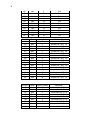
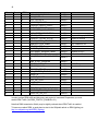
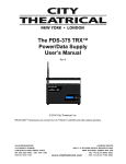
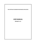
®
7400-5707 SHoW DMX Vero
Transceiver
User’s Manual
Rev 2
© 2012 City Theatrical, Inc.
SHoW DMX Transceivers are covered by U.S. Patent # 7,432,803 and other patents pending.
2
Radio Compliance Information .................................................................................... 3 Antennas..................................................................................................................... 4 5792 SHoW DMX Neo Radio Module CE Declaration of Conformity...................... 6 System Compliance Information.................................................................................. 7 Safety Notices, Ratings and Power Requirements..................................................... 7 Introduction ................................................................................................................... 8 Setting up the 7400-5707 SHoW DMX Vero Transceiver ............................................ 9 Installation .................................................................................................................. 9 Warning....................................................................................................................... 9 Important use notes ................................................................................................... 9 Grounding................................................................................................................... 9 Mounting Bracket ................................................................................................................ 9 Surface Mounting ................................................................................................................ 9 Mounting Orientation ............................................................................................... 10 Pipe Mounting .................................................................................................................... 10 Cable or Conduit Entry ...................................................................................................... 11 Mains Wire Installation and Termination ......................................................................... 11 DMX512 Wire Termination ................................................................................................ 11 Installing the Cover ........................................................................................................... 12 The 7400-5707 SHoW DMX Vero Transceiver Settings ......................................... 13 Configuration ..................................................................................................................... 13 SHoW ID.............................................................................................................................. 14 Neo Mode Operation .......................................................................................................... 14 Neo SHoW ID Tables ......................................................................................................... 14 Neo Adaptive Mode Operation ......................................................................................... 16 Neo Adaptive SHoW ID Table ........................................................................................... 16 Adjustable Output Power .................................................................................................. 17 Limited Bandwidth Hopping ............................................................................................. 17 Limited Burst DMX Output ................................................................................................ 17 RDM Operation ................................................................................................................... 17 Optional or Custom Antenna Accessories ............................................................ 19 3
Radio Compliance Information
5792 SHoW DMX Neo Radio Transceiver
FCC ID: VU65792
IC ID:
7480A5792
FCC Part 15
This equipment has been tested and found to comply with the limits for a Class B digital device, pursuant to part 15 of
the FCC Rules. These limits are designed to provide reasonable protection against harmful interference in a
residential installation. This equipment generates, uses and can radiate radio frequency energy and, if not installed
and used in accordance with the instructions, may cause harmful interference to radio communications. However,
there is no guarantee that interference will not occur in a
particular installation.
If this equipment does cause harmful interference to radio or television reception, which can be determined by turning
the equipment off and on, the user is encouraged to try to correct the interference by one or more of the following
measures:
• Reorient or relocate the receiving antenna.
• Increase the separation between the equipment and receiver.
• Connect the equipment into an outlet on a circuit different from that to which the receiver is connected.
• Consult the dealer or an experienced radio/ TV technician for help.
Radio Frequency Notifications
FCC Notifications
RF Radiation The Product is an intentional radiator of Radio Frequency (RF) energy. In order to limit RF exposure to
personnel in the immediate area, the Product should be located and installed such that a separation of at least 20
centimeters is maintained between the Product’s antenna and personnel in the vicinity of the device.
Modification Warning
Caution: changes or modifications to this equipment, not expressly approved by City Theatrical Inc. could void the
user’s authority to operate the equipment.
Industry Canada Notifications
This Class B digital apparatus complies with Canadian ICES-003. Operation is subject to the following two conditions:
(1) this device may not cause interference, and (2) this device must accept any interference, including interference
that may cause undesired operation of the device.
Cet appareil numérique de la classe B est conforme à la norme NMB-003 du Canada.
Product Installation and Configuration Guide © City Theatrical Inc. 2007
5792 Approved Antenna
To reduce potential radio interference to other users, the antenna type and its gain should be so chosen that the
equivalent isotropically radiated power (e.i.r.p.) is not more than that permitted for successful communication.
This device has been designed to operate with the antennas listed below. Antennas not included in this list or having
a gain greater than 5 dB are strictly prohibited for use with this device. The required antenna impedance is 50 ohms.
City Theatrical Inc. declares that this product conforms to the specifications listed in this manual, following the
provisions of the European R&TTE directive 1999/5/EC:
City Theatrical Inc. vakuuttaa täten että dieses produkt tyyppinen laite on direktiivin 1999/5/EY oleellisten vaatimusten
ja sitä koskevien näiden direktiivien muiden ehtojen mukainen.
City Theatrical Inc. déclare que le produit est conforme aux conditions essentielles et aux dispositions relatives à la
directive 1999/5/EC.
• EN 301 489-1, 301 489-17 General EMC requirements for Radio equipment.
• EN 60950 Safety
• EN 300 328 Technical requirements for Radio equipment.
CAUTION—This equipment is intended to be used in all EU and EFTA countries.
Outdoor use may be restricted to certain frequencies and/or may require a license for operation. Contact local
Authority for procedure to follow.
Note: ESD precautions should be used when attaching or removing the antenna.
4
Note: Combinations of power levels and antennas resulting in a radiated power level of above 100 mW equivalent
isotropic radiated power (EIRP) are considered as not compliant with the above mentioned directive and are not
allowed for use within the European community and countries that have adopted the European R&TTE directive
1999/5/EC. For more details on legal combinations of power levels and
antennas, contact City Theatrical Inc.
Do not use this product near water, for example, in a wet basement or near a swimming pool.
Avoid using this product during an electrical storm. There may be a remote risk of electric shock from lightning.
Product Installation and Configuration Guide © City Theatrical Inc. 2011
Q52 Regulatory information
Radio Frequency Notifications
Belgique Dans le cas d'une utilisation privée, à l'extérieur d'un bâtiment, au-dessus d'un espace public, aucun
enregistrement n'est nécessaire pour une distance de moins de 300m. Pour une distance supérieure à 300m un
enregistrement auprès de l'IBPT est requise. Pour une utilisation publique à l'extérieur de bâtiments, une licence de
l'IBPT est requise. Pour les enregistrements et licences, veuillez contacter l'IBPT.
France 2.4 GHz Bande : les canaux 10, 11, 12, 13 (2457, 2462, 2467, et 2472 MHz respectivement) sont
complétement libres d'utilisation en France (en utilisation intérieur). Pour ce qui est des autres canaux, ils peuvent
être soumis à autorisation selon le départment. L'utilisation en extérieur est soumis à autorisation préalable et très
restreint. Vous pouvez contacter l'Autorité de Régulation des Télécommunications
(http://www.art-telecom.fr) pour de plus amples renseignements.
Antennas
The model: 5792 can be configured with any one of the approved antennas listed below for
fixed, point-to point one server and one client configuration. When the model: 5792 is configured
for point-to-multipoint one server and multiple clients’ configuration (client’s talk to server only
one at a time), client’s can use any of the approved antennas listed below and the server can
use any of the approved antennas listed below with the exception of the 14dBi antenna.
5792 FCC/IC Approved Antennas:
Manufacturer Model
Type
Connector
Gain
Nearson
S151AH-2450S
Omni whip
SMA plug reverse polarity
5dBi
Nearson
S141AH-2450
Omni whip
SMA plug reverse polarity
2dBi
Nearson
S131AH-2450
SMA plug reverse polarity
2dBi
Nearson
DG102N-2.4/5.25
SMA plug reverse polarity via
provided Antenna Cable
5dBi
Tekfun
F40-N
Omni whip
Omni whip,
outdoor
use
Omni whip,
outdoor
use
Male N
4.5dBi
Centurion
WCP2400MMCX4
MMCX jack on 4” coax pigtail
2.5dBi
Maxrad
MP24008XFPT
SMA plug reverse polarity via
provided Antenna Cable
8dBi
Maxrad
MYP24010PT
SMA plug reverse polarity via
provided Antenna Cable
10dBi
Maxrad
MYP24014PT
SMA plug reverse polarity via
provided Antenna Cable
14dBi
Omni whip
Panel,
outdoor
use
Yagi,
outdoor
use
Yagi,
outdoor
use
5
5792 CE Approved Antennas:
Manufacturer Model
Type
Connector
Gain
Nearson
S151AH-2450S
Omni whip
SMA plug reverse polarity
5dBi
Nearson
S141AH-2450
Omni whip
SMA plug reverse polarity
2dBi
Nearson
S131AH-2450
DG102N-2.4/5.25
SMA plug reverse polarity
SMA plug reverse polarity
via provided Antenna Cable
2dBi
Nearson
Tekfun
F40-N
Omni whip
Omni whip,
outdoor use
Omni whip,
outdoor use
Centurion
WCP2400MMCX4
Omni whip
5dBi
Male N
4.5dBi
MMCX jack on 4” coax
pigtail
2.5dBi
For installations governed by FCC and/or IC rules, any of the approved antennas listed above
may be used with the SHoW DMX Vero Transceiver (please note the special installation
requirements for use with the CTI # 5636 14 dBi Yagi Antenna).
Please note that some of the antennas listed are intended for indoor use only.
For use in locations governed by CE rules, some antenna restrictions apply. Antennas from the
5792 CE Approved Antennas meet all requirements. Contact City Theatrical for details.
ETSI power settings for all 5792 SHoW DMX Neo Radio module equipped products, including
the SHoW DMX Vero Transceiver, are based on use with the CTI 5630 5 dBi Omni Antenna.
ETSI power and range will vary with the antenna used. Contact your dealer or City Theatrical
for more information. CE Mark Conformity
6
5792 SHoW DMX Neo Radio Module CE Declaration of Conformity
7
System Compliance Information
The 7400-5707 SHoW DMX Vero Net Transceiver is ETL Listed,
Conforms to UL 508A
The 7400-5707 SHoW DMX Vero Net Transceiver is CE Certified
Standards Applied:
EN 55203-1: 2009
EN 55203-2: 2009
EN 301 489-1 V1.8.1
EN 301 489-3 V1.4.1
EN 60950-1:2006 / A1:2010
FCC Rules, Part 15, Subpart B, Sections 15.107 and 15.109
Products Conform to CE Marking Directive 93/68/EEC
All SHoW DMX Neo models are RoHS compliant
Safety Notices, Ratings and Power Requirements
Please read this entire manual before using your new equipment. Please keep the manual in a
safe place so you can refer to it in the future as required.
The SHoW DMX Neo System is intended for use only by qualified professionals. Connection,
installation and hanging of this equipment must be performed in accordance with all pertinent
local, regional and national safety codes and regulations.
The 7400-5707 SHoW DMX Vero Transceiver is intended for indoor or outdoor use.
The unit enclosure is rated NEMA 4 / IP66.
Rated operating voltage; 100-240VAC 50/60 Hz, 1A max.
This device must be provided with a 20A branch circuit breaker or equivalent suitable external
disconnecting device.
Maximum operating temperature: 0°C - 40°C.
Warning: The 7400-5707 SHoW DMX Vero Net Transceiver must be mounted exclusively in an
upright mounting position with the cable entries on the bottom and antenna connector on the top
as shown in the Installation guide. See the Installation Guide in this document for details.
RF Exposure: The antenna(s) used for this transmitter must be installed to provide a
separation distance of at least 20cm from all persons and must not be collocated or operating in
conjunction with any other antenna or transmitter.
8
Introduction
Thank you for using City Theatrical’s 7400-5707 SHoW DMX Vero Transceiver.
The 7400-5707 SHoW DMX Vero Transceiver features include:
NEMA 4 /IP 66 rated enclosure
Transceiver, fully configurable for Transmit or Receive
One model, FCC, IC and CE Certified
New DMX synchronized hopping structure with increased interference immunity,
reduced interference generation and extremely low latency
Selectable true Adaptive Spread Spectrum Frequency Hopping (ASSFH) in Neo Modes
Two Operating Modes:
Neo Mode
Fully configurable using RDM commands from an external RDM controller or the host.
Replace missing packets with previously received data if any are lost
7mS typical latency
Selectable Output power (1-72mW ETSI)
Selectable Bandwidth
Selectable Burst Length (when used with full frame sources)
Allows for shortened frame data (less than 512 bytes from source)
Enhanced RDM Proxy performance
Neo-Adaptive Mode
Fully configurable using RDM commands from an external RDM controller or the host.
Replace missing packets with previously received data if any are lost
7mS typical latency
Adaptive Hopping
Selectable Output power (1-72mW ETSI)
Allows for shortened frame data (less than 512 bytes from source)
Every effort has been made to anticipate your questions in this manual, but if you have any
questions that are not answered here, or you want to discuss a special application, please feel
free to contact us directly at City Theatrical.
9
Setting up the 7400-5707 SHoW DMX Vero Transceiver
Installation
Install the SHoW DMX Vero Transceiver in a suitable location, following the instructions below.
When selecting a mounting location, note that for best results the antennas in your system must
be within sight of each other.
Warning
To avoid electric shock, do not energize any circuits before all internal and external electrical
and mechanical clearances are checked to assure that all assembled equipment functions
safely and properly.
Important use notes
This unit must be used with voltages below 600V
This unit must be installed in accordance with the National Electrical Code, ANSI/NFPA 70,
where the ambient temperature does not exceed 40°C (104°F) maximum.
Grounding
This enclosure has been provided with a ground bond jumper for ground connection between
the back box and the cover. This jumper must be installed as shown in the drawing below,
using the provided hardware.
Mounting Bracket
The provided mounting Bracket Base can be mounted on a surface or a vertical pipe. For
surface mounting, the Bracket base is provided with slots and holes suitable for #10 / M4
screws or similar fasteners.
Surface Mounting
Mount the Mounting Bracket Base in the desired location using four x #10 / M4 screws (by
others, as above).
10
Slide the mating Mounting Bracket (attached to the Unit) into the Mounting Bracket Base until
the locking clip engages, and install the provided 8-18 x .500” SS Thread Forming Torx Button
Head Security Screw in the hole on the left side of the Bracket assembly.
Mounting Orientation
The 7400-5707 SHoW DMX Vero Transceiver must be mounted exclusively in an upright
mounting position with the cable entries on the bottom and antenna connector on the top as
shown in the drawing above.
Pipe Mounting
The SHoW DMX Vero can also be mounted on a pipe.
Attach the Mounting Bracket Base to a pipe using a stainless steel hose clamp as shown:
Slide the mating Mounting Bracket (attached to the Unit) into the Mounting Bracket Base until
the locking clip engages, and install the retaining Screw.
11
Cable or Conduit Entry
The unit enclosure is provided with ½” NPT entry holes fitted with liquid-tight cable grips for use
with outdoor use cables (by installer) for power and DMX connection. The recommended
torque for these cable grips is as follows:
Locking Nut Sealing Nut 40‐45 inch pounds 50‐55 inch pounds If outdoor use conduit is used instead, it is recommended that the conduit be sealed after
installation to prevent moisture entry, including free air exchange, in order to minimize the
chance of condensation buildup.
Mains Wire Installation and Termination
Install the mains cable or conduit in the entry provided as shown in the drawing below. A liquid
tight cable grip is provided for use with suitable outdoor rated cable with diameter range of
.170”/4,3mm - .450”/11,4mm.
When cable is used, strip outer jacket 6”/150mm.
The mains connection is a 3 pos. plug/socket type terminal block which may be disconnected
for ease of assembly. Strip insulation from individual conductors .25”/7mm and terminate in the
provided screw terminal socket (see illustration above) Mains terminations are ash shown and
are marked on the unit.
DMX512 Wire Termination
The SHoW DMX Vero Net Transceiver is provided with a PCBA mount terminal block for DMX
connection (see illustration above). DMX Input / Output connections are as shown and are
marked on the unit.
12
Installing the Cover
The 7400-5707 SHoW DMX Vero Transceiver has a two part cover, with the outer plastic cover
connected to the inner metal cover with a hinge. Install the metal inner cover using the eight
provided 6- 32 x .375” SS Truss Head Machine Screws. Hand install these screws until the
screw threads are fully engaged with the mating PEM Nut, then tighten to 4 inch pounds.
The outer cover is then closed and secured with the provided 8-18 x .500” SS Thread Forming
Torx Button Head Security Screw, installed in the provided hole on the left side of the cover
assembly.
13
The 7400-5707 SHoW DMX Vero Transceiver Settings
Internal Markings
Configuration
You can configure the Vero Transceiver’s basic operating settings using the System Settings
(SHoW ID and Configuration) switches shown in the detail above.
Configuration switches:
P5, DMX Term: DMX512 termination On or Off. Turn On for end-of-line DMX512
connection.
14
P4, Rx/Tx: Receiver (Rx) On, or Transmitter (Tx) Off. Selects Receiver or Transmitter
operation
P3, Reset: On or Off. Switch On to hold in Reset
P2 Bootloader: On or Off. Sets the unit to Bootloader mode to upload and install radio
firmware upgrades from a connected SHoW DMX Neo Transceiver or Receiver.
P1 Default: On or Off. To restore the system to factory default settings:
1. Set P1 Default to On
2. Wait for Data Present LED to blink rapidly
3. Switch P1 to Off
SHoW ID
Like the original SHoW DMX Classic system, the SHoW DMX Neo system uses SHoW IDs as a
quick way to set RF configuration options. Each SHoW ID represents a combination of one of
16 hopping patterns and one of four bandwidth settings. 7400-5707 Vero Transceiver supports
Neo and Neo Adaptive SHoW IDs only.
The Transmitter and Receiver SHoW IDs must match for the units to communicate.
The SHoW DMX Vero Transceiver is preset at the factory with SHoW ID 201 for Adaptive
Spread Spectrum Frequency Hopping and Neo Low Latency broadcast mode.
SHoW ID may be set manually using the SHoW ID rotary switches or using RDM. Whichever
method is used last takes precedence. The unit maintains the last used setting over power
cycles, and checks on power up to see if switches have been changed while the unit was off.
To set the SHoW ID manually, simply set the SHoW ID Rotary Switches to the desired SHoW
ID.
In order to use RDM, you will also need an RDM controller or a lighting control console with a
built-in RDM controller (see below).
Neo Mode Operation
In Neo Mode, the SHoW DMX Vero Transceiver uses a new broadcast format that reduces
latency to ~ 7mS max and provides further resistance to interference susceptibility or creation.
Neo Mode supports Adjustable Broadcast Power, Limited Bandwidth, Limited Burst, and
provides 64 new SHoW IDs, providing 16 hopping patterns in each Bandwidth setting.
Neo SHoW ID Tables
SHoW
ID
101
102
103
104
105
Mode
Neo
Neo
Neo
Neo
Neo
Hopping
Pattern
1
2
3
4
5
Bandwidth
Full
Full
Full
Full
Full
15
106
107
108
109
110
111
112
113
114
115
116
Neo
Neo
Neo
Neo
Neo
Neo
Neo
Neo
Neo
Neo
Neo
6
7
8
9
10
11
12
13
14
15
16
Full
Full
Full
Full
Full
Full
Full
Full
Full
Full
Full
SHoW ID
117
118
119
120
121
122
123
124
125
126
127
128
129
130
131
132
Mode
Neo
Neo
Neo
Neo
Neo
Neo
Neo
Neo
Neo
Neo
Neo
Neo
Neo
Neo
Neo
Neo
Hopping Pattern
1
2
3
4
5
6
7
8
9
10
11
12
13
14
15
16
Bandwidth
Limited Low, Wi-Fi 1-6
Limited Low, Wi-Fi 1-6
Limited Low, Wi-Fi 1-6
Limited Low, Wi-Fi 1-6
Limited Low, Wi-Fi 1-6
Limited Low, Wi-Fi 1-6
Limited Low, Wi-Fi 1-6
Limited Low, Wi-Fi 1-6
Limited Low, Wi-Fi 1-6
Limited Low, Wi-Fi 1-6
Limited Low, Wi-Fi 1-6
Limited Low, Wi-Fi 1-6
Limited Low, Wi-Fi 1-6
Limited Low, Wi-Fi 1-6
Limited Low, Wi-Fi 1-6
Limited Low, Wi-Fi 1-6
SHoW ID
133
134
135
136
137
138
139
140
141
Mode
Neo
Neo
Neo
Neo
Neo
Neo
Neo
Neo
Neo
Hopping Pattern
1
2
3
4
5
6
7
8
9
Bandwidth
Limited Mid, Wi-Fi 5-9
Limited Mid, Wi-Fi 5-9
Limited Mid, Wi-Fi 5-9
Limited Mid, Wi-Fi 5-9
Limited Mid, Wi-Fi 5-9
Limited Mid, Wi-Fi 5-9
Limited Mid, Wi-Fi 5-9
Limited Mid, Wi-Fi 5-9
Limited Mid, Wi-Fi 5-9
16
142
143
144
145
146
147
148
Neo
Neo
Neo
Neo
Neo
Neo
Neo
10
11
12
13
14
15
16
Limited Mid, Wi-Fi 5-9
Limited Mid, Wi-Fi 5-9
Limited Mid, Wi-Fi 5-9
Limited Mid, Wi-Fi 5-9
Limited Mid, Wi-Fi 5-9
Limited Mid, Wi-Fi 5-9
Limited Mid, Wi-Fi 5-9
SHoW ID
149
150
151
152
153
154
155
156
157
158
159
160
161
162
163
164
Mode
Neo
Neo
Neo
Neo
Neo
Neo
Neo
Neo
Neo
Neo
Neo
Neo
Neo
Neo
Neo
Neo
Hopping Pattern
1
2
3
4
5
6
7
8
9
10
11
12
13
14
15
16
Bandwidth
Limited High, Wi-Fi 7-11
Limited High, Wi-Fi 7-11
Limited High, Wi-Fi 7-11
Limited High, Wi-Fi 7-11
Limited High, Wi-Fi 7-11
Limited High, Wi-Fi 7-11
Limited High, Wi-Fi 7-11
Limited High, Wi-Fi 7-11
Limited High, Wi-Fi 7-11
Limited High, Wi-Fi 7-11
Limited High, Wi-Fi 7-11
Limited High, Wi-Fi 7-11
Limited High, Wi-Fi 7-11
Limited High, Wi-Fi 7-11
Limited High, Wi-Fi 7-11
Limited High, Wi-Fi 7-11
Neo Adaptive Mode Operation
The SHoW DMX Vero Transceiver can be configured to operate in the new Neo Adaptive
(AFHSS) Mode. Neo Adaptive Mode uses an Adaptive Spread Spectrum Frequency Hopping
broadcast format in which the system detects interference and adapts its frequency hopping
channel set automatically to avoid it.
Neo Adaptive Mode supports Adjustable Broadcast Power and provides 4 new Adaptive Mode
SHoW IDs. Latency is also reduced to ~7mS max in Adaptive Mode.
Neo Adaptive SHoW ID Table
SHoW ID
201
202
203
204
Mode
Neo Adaptive
Neo Adaptive
Neo Adaptive
Neo Adaptive
Hopping Pattern
Adaptive
Adaptive
Adaptive
Adaptive
Bandwidth
Full
Full
Full
Full
17
Adjustable Output Power
The broadcast power of the SHoW DMX Vero Transceiver is adjustable to allow the user to
calibrate the system’s broadcast power to match the requirements of the application.
Limited Bandwidth Hopping
In the Limited Bandwidth Hopping mode, the SHoW DMX Vero Transceiver system is assigned
to one of three sub-bands of the full 2.4Ghz spectrum. Each sub-band occupies approximately
2/5s of the full band, with one sub-band positioned at the low end, one in the center, and one at
the high end of the full spectrum. The three sub-bands overlap and each avoids some
combination of WiFi channels. This will allow the SHoW DMX Vero Transceiver to be set to
broadcast in a different area of the spectrum than other equipment being used in the area, to
minimize or eliminate interference with WiFi or other channel specific or limited bandwidth
equipment.
Limited Burst DMX Output
Limited Burst mode reduces the number of DMX channels and the amount of radio energy that
is broadcast by the Transmitter.
If you don’t need all 512 DMX values and you need to control the radio energy in your system
as much as possible, then you can use Limited Burst to target only the DMX channels you need,
and reduce your radio footprint even further.
In Limited Burst mode, the user may select a contiguous group of 51 slots or more DMX slots in
multiples of 52 slots (51+52, 51+104, etc.). Limited Burst slot counts include: 51, 103, 155, 207,
259, 311, 363, 415, and 467. These may be assigned to any starting address that will not
exceed the total 512 slot count when added to the remaining slots in the selected Burst size
(e.g. with 467 slots, the highest allowed starting address is 46, as 46+466 = 512).
RDM Operation
RDM stands for Remote Device Management. RDM is a lighting control protocol enhancement
to DMX512 specified by PLASA (formerly ESTA); the official name is ANSI/ESTA E1.20,
Entertainment Technology - Remote Device Management over USITT DMX512.
Using RDM, you can select one of the 68 available Neo SHoW IDs, adjust the broadcast power,
configure for limited burst transmission, edit the RDM Device Label, and enable or disable RDM
traffic.
The SHoW DMX Vero Transceiver is fully enabled as an RDM proxy system, so you can use
RDM to manage your SHoW DMX Vero Transceiver system and any connected RDM
responders that are downstream of the system.
Remember that when RDM is enabled, the system uses ~ 25% of its available DMX bandwidth
for RDM so DMX fidelity and refresh rate are reduced. For best DMX fidelity, disable RDM
traffic from the Receivers back to the Transmitting unit when you are not using RDM.
You can use RDM to change SHoW IDs in connected devices. Remember that once you have
changed the SHoW ID in a connected Receiver, you will lose communication with that Receiver
until you change your Transmitter to the matching SHoW ID.
The SHoW DMX Vero Transceiver supports the following RDM PIDs:
Get
Set
Reduce
RDM Parameter
PID
Comment
18
Allowed
X
X
X
X
X
X
X
X
X
X
X
X
X
Allowed
X
X
d RDM
X
X
X
X
X
X
X
X
X
X
X
X
X
X
X
X
X
X
X
X
X
X
X
X
X
X
X
X
X
X
X
X
X
X
X
X
X
X
X
X
X
X
X
X
X
X
X
DISC_UNIQUE_BRANCH
DISC_MUTE
DISC_UN_MUTE
PROXIED_DEVICES
PROXIED_DEVICE_COUNT
QUEUED_MESSAGE
SUPPORTED_PARAMETERS
PARAMETER_DESCRIPTION
DEVICE_INFO
PRODUCT_DETAIL_ID_LIST
DEVICE_MODEL_DESCRIPTION
MANUFACTURE_LABEL
DEVICE_LABEL
FACTORY_DEFAULTS
SOFTWARE_VERSION_LABEL
DMX_PERSONALITY
DMX_PERSONALITY_DESCRIPTIO
N
DMX_START_ADDRESS
SENSOR_DEFINITION
SENSOR_VALUE
IDENTIFY_DEVICE
RDM_TRAFFIC_ENABLE
SHOW_ID
OUTPUT_POWER
HOP_PATTERN
BANDWIDTH
LATENCY
DMX_RDM_ INTERLEAVE_RATIO
PROXIED_DEVICES_ENHANCED
ADAPTIVE_ON_OFF
0x0001
0x0002
0x0003
0x0010
0x0011
0x0020
0x0050
0x0051
0x0060
0x0070
0x0080
0x0081
0x0082
0x0090
0x00C0
0x00E0
Reports Category 0x0801
Repots ID 0x0604
City Theatrical, Inc.
Reports CE/FCC
Sets Limited Burst
0x00E1
0x00F0
0x0200
0x0201
0x1000
0x7FE2
0x8000
0x8001
0x8002
0x8003
0x8019
0x801B
0x801C
0x801D
RSSI, Temp
Draft
In order to allow RDM traffic and discovery and control of connected Responders you must
enable RDM Traffic (Set RDM_TRAFFIC_ENABLE to 01).
Note that DMX transmission fidelity may be slightly reduced when RDM Traffic is enabled.
To learn more about RDM, a good place to start is the Wikipedia article on RDM (lighting) at:
http://en.wikipedia.org/wiki/RDM_(lighting)
19
Optional or Custom Antenna Accessories
You system may have been supplied with optional or custom antenna distribution accessories
such as antennas, splitters, attenuators, lighting arrestors, or other devices. Please contact City
Theatrical directly for details.