1
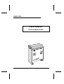
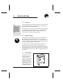
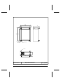
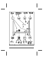
victron energie
USER MANUAL
GEBRUIKSAANWIJZING
GEBRAUCHSANWEISUNG
Victron Skylla 24/15
SECTIONS
ENGLISH
1
NEDERLANDS
29
DEUTSCH
57
This page intentionally left blank.
ENGLISH
USER MANUAL
Victron Skylla 24/15
user manual
page 1
This page intentionally left blank.
subject to change without notice
page 2
SK01001E070494 / 070494 / RV user manual
INTRODUCTION
Victron Energie has established an international reputation as
a leading designer and manufacturer of power systems. Our
R&D department is the driving force behind this reputation. It
is continually seeking new ways of incorporating the latest
technology in our products. Each step forward results in valueadding technical and economical features.
Our proven philosophy has resulted in a full range of state-ofthe-art equipment for the supply of electrical power. All our
equipment meets the most stringent requirements.
Victron Energie systems provide you with high-quality AC
supplies at places where there are no permanent sources of
mains power.
An automatic stand-alone power system can be created with a
configuration comprising a Victron Energie inverter, battery
charger, mains manager (if required) and, last but not least,
batteries with sufficient capacity.
Our equipment is suitable for countless situations in the field,
on ships or other places where a mobile 230-Voltac power supply is indispensable.
Victron Energie has the ideal power source for all kinds of
electrical appliances used for household, technical and administrative purposes, including instruments susceptible to interference. All of these applications require a high-quality power
supply in order to function properly.
Victron Skylla battery charger model 24/15
This manual contains directions for installing the Skylla battery charger model 24/15. It describes the functionality and
operation of the Skylla battery charger, including its protective devices and other technical features.
user manual
page 3
This page intentionally left blank.
page 4
user manual
CONTENTS
1.
Description
1.1 General
1.2 Skylla charger
1.3 Description
1.4 Protection
2.
Installation
2.1 Mounting
2.2 Connections
2.2.1
Earthing
2.2.2
Mains input
2.2.3
Battery output
2.2.4
Diode splitter
2.2.5
Battery voltage alarm
9
9
9
9
9
9
11
12
Start up
13
13
13
13
14
14
3.
3.1 Operating
3.1.1
Automatic charging mode
3.1.2
Permanent boost mode
3.1.3
Permanent float mode
3.1 Maintenance
4.
5.
Calibration
4.1 Adjusting the charge voltage
4.2 Setting the charge voltage
15
15
15
Fault tracing diagrams
Fault finding
Battery charger does not work
Batteries are being overcharged
Batteries are not being charged
17
17
18
19
20
Specifications
Input
Output
General
Environment
Mechanical
Connections
23
23
23
24
24
24
24
Drawings
25
26
27
5.1
6.
6.1
6.2
6.3
6.4
6.5
6.6
7.
7
7
7
7
8
Victron Skylla 24/15 dimensions
Victron Skylla 24/15 connections
user manual
page 5
This page intentionally left blank.
page 6
user manual
1.
DESCRIPTION
1.1
IP21=
protection against
materials larger
than 12 mm (for
example a finger)
and protection
against vertical
descending waterdrops (condensation).
General
All Victron Skylla 24/15 battery chargers are subjected to full
functional testing before leaving the factory. They are properly packed for secure transportation.
The Skylla 24/15 is housed in a IP21 specification aluminium
case designed for wall or floor mounting. The mains input,
battery output and alarm output (if used) connections are
made close to the under side of the housing.
1.2
Skylla charger
The Skylla 24/15 is designed for a 24V lead-acid battery system. The maximum charging current is 15A. The recommended battery capacity is 60 to 150 Ah. The standard Skylla
24/15 is suitable for traction batteries. Please consult your local Victron Energie agent for more details.
The Skylla 24/15 is a fully automatic battery charger. It is
powered by mains (230V 50/60 Hz nominal supply - see
specifications). It is designed to be permanently connected to
the lead-acid batteries. It is no longer necessary to disconnect
the charger during long term storage, for example during winter storage.
1.3
Description
The Skylla 24/15 will
charge the battery as
soon as the power
switch is turned on, provided there is a mains
supply. If automatic
charge mode is selected
(see connection diagram), the battery will
be charged with the
user manual
page 7
built in IUoUo characteristic. The float voltage is factory preset to 26,5 V. The boost voltage is factory preset to 28,5 V.
The boost and float voltages are user adjustable (see 4).
Warning: Because of the extremely high voltages
permanently present within the Skylla 24/15, we
insist that only a qualified electrician makes all the
connections and adjustments within the charger.
Make sure the Skylla 24/15 is turned off when connecting, and use an insulated electrician’s screwdriver to make all connections and to adjust the
voltage and current control.
1.4
Protection
The Skylla 24/15 is inherently safe due to its robust design.
The output current is fully short circuit protected. The output
current is internally limited under all conditions (see specifications). The battery cables are thus protected in the event of a
short circuit.
If the internal temperature of the Skylla 24/15 increases, the
output current decreases accordingly. Under extreme conditions (the ventilation holes could be blocked, or the fan may
be jammed) the internal temperature will become too high,
and the machine will shut itself down. When the internal temperature is again within limits, the Skylla 24/15 will resume
operation.
page 8
user manual
short-circuit
current =
current supplied
when a shortcircuit on the output occurs.
2.
INSTALLATION
2.1
Mounting
Wall or floor mount the Skylla 24/15 in a dry, well ventilated
area. Excessively high ambient temperatures may adversely
affect the output current and the lifetime of the Skylla 24/15.
Best results are obtained in such conditions if the Skylla
24/15 is wall mounted.
2.2
Earth =
(PE): yellow and
green striped colour wire
Phase =
(L): brown or black
colour wire
Neutral =
(N): blue colour
wire
Connections
2.2.1 Earthing
The Skylla 24/15 is not
a double insulated
charger. The PE terminal must be connected
to a true earth under all
conditions. On a boat,
the earth terminal on
the under side of the
housing must be connected to the ground
Illustration 1. Position of earthing
plate or the hull. The
screw
shore connection must
be earthed to the PE terminal on the mains input connection block. For mobile applications (car, caravan etcetera) earth terminal must be connected to the metal chassis.
2.2.2 Mains input
Use a three core approved cable to connect the Skylla 24/15
to the mains. Remember that the PE terminal must always be
earthed.
2.2.3 Battery output
It is important that the connection between the Skylla 24/15
and the battery is made in such a way that power loss is minimised. The cables must be as short and as thick as possible to
user manual
page 9
© victron energie b.v.
drawing no.: SK01003E
date : 020394
revision no.: 0001
Skylla 24/15 connections
Illustration 2. Position of connectors, LED’s and fuses
reduce resistance. We recommend using cable shoes as supplied. We recommend the following minimum copper cross
section for these battery cables:
Length
cross section
length 0-1.5 meters
4 mm2
length 1.5 - 6 meters
10 mm2
Cable lengths in excess of 6 meters are not recommended.
The Skylla 24/15 has an output fuse to ensure that the battery
cables are protected in the event of an internal short circuit.
Furthermore, the output current of the Skylla 24/15 is limited
(see specifications).
page 10
user manual
2.2.4 Diode splitter
A diode splitter can be connected to the Skylla 24/15. The output voltage must be increased to compensate for the voltage
drop over the diode splitter.
Warning: Because of the extremely high voltages
permanently present within the Skylla 24/15, we
insist that only a qualified electrician makes
adjustments in the Skylla 24/15. Make sure the
Skylla 24/15 is turned off when connecting, and use
an insulated electrician’s screwdriver to make all
connections and to adjust the voltage or current
control.
The following procedure must be followed:
victron energie
step 1
Remove the front panel of the Skylla 24/15.
step 2
Connect the mains input onto the charger. Remove all
loads on the machine.
step 3
Switch the machine on.
step 4
Use an accurate volt meter on the + and - terminals to
measure the no-load voltage. Adjust the output voltage
by turning on the ‘voltage control’ potentiometer to 0,7
V more than the desired float voltage for the battery .
Normally this is 26,5 + 0,7 = 27,2 V.
user manual
page 11
Note:
The 0,7 V compensation is a realistic estimate for
most diode splitters. If absolute accuracy is required,
continue by now connecting the diode splitter and
the batteries onto the charger. Wait until the batteries
are fully charged, and adjust the ‘voltage control’ potentiometer until the voltage on the battery side of
the diode splitter becomes the desired float voltage.
Remember that the boost voltage is automatically adjusted along with the float voltage. It is not possible
to adjust the boost voltage independently.
step 5
Place the front panel back on to the unit.
2.2.5 Battery voltage alarm
The Skylla 24/15 has a potential free contact which is closed
if the battery voltage is out of range for more than 1 minute.
The contact is activated if the battery voltage is higher than
33,6 V or lower than 23,8 V. This potential free contact can be
used to energise a remote alarm. Consult your dealer for more
details about the possible applications of this alarm. The maximum current through this contact is detailed in the specification.
page 12
user manual
3.
START UP
3.1
LED =
Light Emitting
Diode
V.D.L. =
Victron charging
system
float charge
mode =
recharging
boost charge
mode =
initial charging
Operating
On the front panel of the Skylla 24/15 a power switch and
two LED’s can be found. Switch on the charger by operating
the power switch. The ‘on’ LED will light, and if the battery
is not completely full, the ‘boost’ LED will light. The batteries are charged without any switch on delay.
3.1.1 Automatic charging mode
As the charge in the batteries increases, the charge current decreases. The charger is in ‘boost’ mode while the charge current is greater than 1 A. In this mode, the output voltage will
rise to 28,5 V.
When the charge current decreases to below 1 A, the Skylla
24/15 will switch over to ‘float’ mode. The output voltage
will drop to 26,5 V.
The above mentioned voltages are recommended by most battery manufacturers to ensure optimal charging of 24 V leadacid batteries. The Skylla 24/15 can be left connected on to
the batteries during long periods of time without the risk of
gas discharge due to overcharging. The batteries are kept in
optimal condition under all conditions. We recommend that
you select this mode for long battery life.
Note:
To select automatic charge mode, the supplied
jumper must be placed in such a way that there is
no connection between any pins of the mode selector (see connection diagram). Alternatively, the
jumper can be removed and stored elsewhere.
3.1.2 Permanent boost mode
Permanent boost mode can be selected by placing the supplied jumper between pins 2 and 3 of the mode selector (see
connection diagram). The battery will be charged up to
28,5 V.
user manual
page 13
In some cases, for example after a deep discharge, it is good
to charge the batteries up to 28,5 V for a period of 24 hours.
We however do not recommend placing the Skylla 24/15 in
permanent boost mode for extended periods because of the
danger of gas discharge.
We do not recommend permanent boost mode for sealed type
lead-acid batteries. When charging open type batteries, you
are advised to top these up regularly with distilled water.
For further information, contact your local Victron Energie
dealer.
3.1.3 Permanent float mode
Permanent float mode can be selected by placing the supplied
jumper between pins 1 and 2 of the mode selector (see connection diagram). The battery will be charged up to
26,5 V. There is no danger of gas discharge due to overcharging.
Permanent float mode is recommended for certain sealed type
lead-acid batteries designed for standby use only. For further
information, contact your local Victron Energie dealer.
3.2
Maintenance
The Skylla 24/15 requires no special maintenance. It is however recommended that the electrical connections be checked
once a year, and that the charger is kept dry, clean and dust
free. If any problems arise, use the fault finding procedure in
this manual to trace the fault.
We also recommend cleaning the fan once every two years
(for position of the fan, see illustration 1 on page 3). If the fan
is worn, contact your local Victron Energie dealer to have the
fan replaced.
page 14
user manual
4.
CALIBRATION
4.1
Adjusting the charge voltage
The float voltage is factory preset to 26,5 V. The boost voltage is factory preset to 28,5 V. The boost and float voltages
are user adjustable. These values are recommended by almost
all lead-acid battery manufacturers. The current and voltage
settings do not have to be periodically checked.
Warning: Because of the extremely high voltages
permanently present within the Skylla 24/15, we
insist that only a qualified electrician makes any
adjustments within the charger. Make sure the
Skylla 24/15 is turned off when connecting,
and use an insulated electrician’s screwdriver
to make all connections and to adjust the
voltage and current control.
If you want to adjust the charge voltage, remove the front
panel of the Skylla 24/15. Unscrew the four countersunk
screws with a Phillips screwdriver, and pull the panel free.
4.1.1 Setting the charge voltage.
The boost and charge voltages cannot be set independently.
The boost voltage is always 2 V more than the float voltage.
To set the float voltage, disconnect all loads from the charger.
Measure the output voltage with an accurate voltmeter. Adjust
the float voltage to the value recommended by the battery
manufacturer.
user manual
page 15
This page intentionally left blank.
page 16
user manual
5.
FAULT FINDING
5.1
#@ & grr 1
@$6 48?!! >v
%/J s!!?" f%
Fault finding
The following 3 diagrams are included to assist you in finding
the fault. Experience has shown that most faults can be solved
with this procedure. Before checking the Skylla 24/15, remove all loads form the charger, and connect the unit to mains
supply.
The following conditions are covered by the diagrams:
❐
battery charger does not work
❐
batteries are being overcharged
❐
batteries are not being fully charged
user manual
page 17
© victron energie b.v.
page 18
Skylla 24/15 Fault tracing flow chart no. 1
user manual
drawing no.: SK01007E
date : 070494
revision no.: 0003
© victron energie b.v.
Skylla 24/15 Fault tracing flow chart no. 2
user manual
drawing no.: SK01008E
date : 020394
revision no.: 0001
page 19
© victron energie b.v.
page 20
Skylla 24/15 Fault tracing flow chart no. 3
user manual
drawing no.: SK01009E
date : 020394
revision no.: 0001
© victron energie b.v.
Skylla 24/15 Fault tracing flow chart no. 4
user manual
drawing no.: SK01010E
date : 070494
revision no.: 0002
page 21
This page intentionally left blank.
page 22
user manual
6.
Specifications
6.1
Input:
Input voltage:
Input voltage protection:
Frequency range:
Input fuse:
Power factor:
Input current:
+
-
6.2
180 - 265V
Unit shuts down if input voltage
drops below 160V. The unit will
resume operation if the input
voltage rises above 165V.
47 - 63Hz
5A fast 5 x 20 mm
0,94 at full load
0,90 at half load
2,4A at 230V input on full load
Output:
Nominal charging voltage:
High charging voltage (boost):
Low charging voltage (float):
Charging characteristic:
Voltage stability:
Output current:
Output current ripple:
Short circuit current:
Short circuit protection:
Output fuse:
Battery voltage alarm:
24V
28,5V
26,5V
IUoUo in accordance with DIN
41772
± 1%
15A at boost voltage
75% rms at full load
20A
Continuous short circuit proof
20A auto blade fuse
A 5A potential free contact is activated if the battery voltage remains above 33,1 V or below
23,2V for more than 60 seconds
All specifications are subject to change without notice
user manual
page 23
6.3
General:
Radio interference suppression:
Electromagnetic compatibility:
Safety:
Diode splitter compensation:
6.4
Environment:
Temperature range:
Cooling:
Fan control:
6.5
Aluminium IP21
Blue (RAL5012) epoxy
280 x 200 x 90
2,75 kg
Connections
Output 24 VDC:
Input 230 VAC plus earth:
page 24
-10 to 50 °C. The charge current
decreases if the temperature rises
above 40 °C
Forced convection
The fan speed is electronically controlled. If the internal temperature
is too high, the unit will shut down.
Mechanical:
Case:
Colour:
Dimensions (h x b x d):
Weight:
6.6
EN55014
IEC 801-2 class 3
IEC 801-3 class 2
IEC 801-4 class 2 for the DC output
IEC 801-4 class 3 for the AC input
IEC 801-5 class 3
PCB designed to IEC950
Compensation by potentiometer
adjustment
M6 bolts
3 pole connector block plus extra
earth terminal on housing
user manual
7.
Drawings
Victron Skylla 24/15 dimensions
26
Victron Skylla 24/15 connections
27
user manual
page 25
200
20
160
88
20
7
240
283
20
23
10.5 mm
73
6.0 mm
12.5
174
© victron energie b.v.
page 26
Skylla 24/15 dimensions
user manual
drawing no.: SK01014E
date : 100394
revision no.: 0001
© victron energie b.v.
Skylla 24/15 connections
user manual
drawing no.: SK01003E
date : 020394
revision no.: 0001
page 27
This page intentionally left blank.
page 28
user manual