1
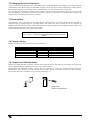
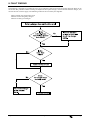
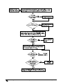
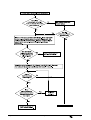
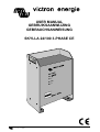
USER MANUAL
GEBRUIKSAANWIJZING
GEBRAUCHSANWEISUNG
SKYLLA 24/100 3-PHASE CE
SECTIONS:
ENGLISH
NEDERLANDS
DEUTSCH
2
17
37
Victron Energy BV
De Paal 35
1351 JG Almere-Haven
The Netherlands
Article number
Document number
Version
Date
phone: ** 31 - (0) 36 - 535 9700
fax:
** 31 - (0) 36 - 531 1666
Subject to change without notice. * Wijzigingen onder voorbehoud. *
victron energy
manual Skylla 24/100 3F
: ISM010022000
: ISM010022000
: 04
: 20 November 2001
Änderungen vorbehalten.
Page 1
USER MANUAL ENGLISH
1. INTRODUCTION
3
2. DESCRIPTION
2.1 Maintenance
4
4
3. PROTECTION
3.1 Short circuit protection
3.2 Temperature protection
3.3 Input protection
5
5
5
5
4. COMPENSATED CHARGING
4.1 Temperature sensor
4.2 Voltage sensing
6
6
6
5. INSTALLATION
5.1 Connecting earth
5.2 Connecting mains
5.3 Connecting the battery
5.4 Connection procedure
7
7
7
7
8
6. START UP
6.1 Operating
6.2 Parallel use
6.3 Battery room ventilators
9
9
9
9
7. CALIBRATION
7.1 Adjusting the charging voltages
7.2 Changing the current limit level
7.3 Diode splitter
7.4 Factory settings
7.5 Jumpers and Potentiometers
10
10
11
11
11
11
8. FAULT FINDING
12
9. SPECIFICATIONS
9.1 Input
9.2 Output
9.3 General
15
15
15
15
10. Drawings
16
Page 2
user manual Skylla 24/100 3F
victron energy
1. INTRODUCTION
Victron Energy
Victron Energy has established an international reputation as a leading designer and manufacturer of power systems.
Our R&D department is the driving force behind this reputation. It is continually seeking new ways of incorporating
the latest technology in our products. Each step forward results in value-adding technical and economical features.
Our proven philosophy has resulted in a full range of state-of-the-art equipment for the supply of electrical power. All
our equipment meets the most stringent requirements.
Victron Energy systems provide you with high-quality AC supplies at places where there are no permanent sources of
mains power.
An automatic stand-alone power system can be created with a configuration comprising a Victron Energy inverter,
battery charger, mains manager (if required) and, last but not least, batteries with sufficient capacity.
Our equipment is suitable for countless situations in the field, on ships or other places where a mobile 230Vac power
supply is indispensable.
Victron Energy has the ideal power source for all kinds of electrical appliances used for household, technical and
administrative purposes, including instruments susceptible to interference. All of these applications require a
high-quality power supply in order to function properly.
The Skylla battery charger 24/100, 3-phase
This manual contains directions for installing the Skylla battery charger 24/100, 3-phase. It describes the functionality
and operation of the Skylla battery charger, including its protective devices and other technical features.
victron energy
manual Skylla 24/100 3F
Page 3
2. DESCRIPTION
The Victron Skylla 24/100, 3-phase battery charger is subjected to full functional testing before leaving the factory. It
is properly packed for secure transportation.
The Skylla 24/100 3-phase charger is a rectifier/charger combination. The output is voltage controlled and the current
is limited. The charger is protected against over-temperature and short circuit of any duration. It is housed in a IP20
specification aluminium case designed for wall or floor mounting. The mains input and battery output connections are
made through the under side of the housing. The Skylla 24/100 3-phase charger is designed for a 24Vdc lead-acid
battery system. The maximum charging current is 100A and the recommended battery capacity is 500 - 1000Ah. The
charger is suitable for traction batteries. Please consult your local Victron Energy agent for more details.The Skylla
24/100 3-phase charger is a fully automatic battery charger. It is powered by 380Vac 50/60 Hz nominal mains supply.
The input can be converted to 415Vac or to 440Vac. The charger is designed to be permanently connected to lead-acid
batteries. It is no longer necessary to disconnect the charger during long term storage, for example during winter
storage.
Illustration 1.
Schematic diagram of the Skylla
1. three phase input transformer;
2. half controlled thyristor bridge rectifier;
3. ripple suppression;
4. DC current shunt
The Skylla will charge the battery as soon as the power switch is turned on, provided there is a mains supply. If
automatic charge mode is selected (5% or 15 % charge mode, see the front panel), the battery will be charged with the
built in IUoUo characteristic. The float voltage is factory pre-set to 26,5Vdc. The boost voltage is factory pre-set to
28,5Vdc. The boost and float voltages are user adjustable. The charger operates with two charge voltages, a high
voltage (boost charge) and a low voltage (float charge). The charger switches automatically from boost charge to float
charge after 1 or 4 hours (see illustration 2).
The charger supplies a constant current to the battery, until the
pre-set boost charge voltage is reached (28.5Vdc). At that
moment (t1) the yellow “Voltage control” LED illuminates
and a clock which determines the boost charge time, is started.
When the pre-set boost charge time expires at t2 the charger
switches to the float voltage (26.5Vdc). The float voltage is
maintained for 20 or 23 hours. After this period, at time t3,
the charger is switched back to the boost charge voltage for 1
or 4 hours.
If current limiting occurs for more than 30 seconds during the
time of the float charging, the clock is started again and starts
a new cycle of boost charging.
Time between (Ill. 2)
High rate (LED)
Voltage controlled (LED)
t0
t1
OFF
OFF
t2
ON
ON
t3
OFF
ON
Illustration 2.
The Skylla 24/100 3-phase
charging characteristics.
2.1 Maintenance
The Skylla 24/100 3-phase charger requires no special maintenance. It is however recommended that the electrical
connections are checked twice a year, and that the charger is kept dry, clean and dust free. If any problems arise, use
the fault finding procedure in this manual to trace the fault.
Page 4
user manual Skylla 24/100 3F
victron energy
3. PROTECTION
The Skylla 24/100 3-phase charger is inherently safe due to its robust design and internal safety features.
3.1 Short circuit protection
The output current is fully short circuit protected. The output current is internally limited under all conditions (see
specifications). The battery cables are thus protected in the event of a short circuit.
3.2 Temperature protection
If the internal temperature of the Skylla 24/100 3-phase charger increases, the output current decreases accordingly.
Under extreme conditions (the ventilation holes could be blocked) the internal temperature will become too high, and
the machine will shut itself down. When the internal temperature is again within limits, the charger will resume
operation.
3.3 Input protection
The input of the Skylla 24/100 3-phase charger is protected by two automatic fuses.
input voltage
380 Vac
415 Vac
440 Vac
victron energy
input fuses
16 Ampere automatic
16 Ampere automatic
16 Ampere automatic
manual Skylla 24/100 3F
Page 5
4. COMPENSATED CHARGING
4.1 Temperature sensor
The Skylla 24/100 3-phase has a temperature compensation facility which adjusts the charger voltage to the battery
temperature. In order to use this facility, a Victron Energy temperature sensor must be fitted to the battery. This is
because a higher charging voltage can be used with a cold battery than with a warm battery. The reference charging
voltage is 28.5Vdc at a battery temperature of 20oC. See illustration 3.
Illustration3.
Temperature
compensated charging.
Connecting the temperature sensor
In order to connect the temperature sensor, jumper J2 must first be moved from pin 2 and 3 to pin 1 and 2. See
drawing SK07010E.
The positive pole "+" of the sensor is connected to terminal E7, and the negative pole "-" is connected to terminal E8
of the battery charger. We recommend twisting the sensor wires, due to possible external electrical interference. If the
battery charger is switched on and the sensor is connected correctly, the LED on the temperature sensor will
illuminate. The temperature sensor can best be placed on top of the battery bank.
o
Battery temperatures of up to -5 C
o
At temperatures of up to -5 C, the charger supplies a maximum charging voltage of 30Vdc. This output voltage is
limited because at higher voltages problems might occur in the external equipment. See illustration 3, section "A".
o
o
Battery temperatures between -5 C and + 47 C
In this temperature range, the output voltage is dependent on battery temperature (as measured by the sensor). As the
temperature increases, the output voltage of the charger decreases by 60 mV/oC (5mV/oC per cell). See illustration 3,
section "B".
High battery temperature
At battery temperatures of +47 oC and above, the charging voltage drops sharply. At values of 50 oC and above, the
charger operates as a rectifier with an output voltage of 24Vdc. See illustration 3, sections "C" and "D".
4.2 Voltage sensing
The Skylla 24/100 3-phase has a full automatic voltage sensing facility
which compensates the chargers output voltage for losses in the battery
cables. See illustration 4. In order to use this facility, two wires must be
connected:
connect E1 to the positive pole of the battery “+”
connect E2 to the negative pole of the battery “-”
The “+/- sense” LED will light up if these wires are connected correctly. See
drawing SK07010E. The Skylla 24/100 3-phase charger is now sensing the
actual charging voltage at the battery poles.
Illustration4.
Connection of the voltage sensing wires.
Page 6
user manual Skylla 24/100 3F
victron energy
5. INSTALLATION
Wall or floor mount the Skylla 24/100 3-phase charger in a dry, well ventilated area. Excessively high ambient
temperatures may adversely affect the output current and the lifetime of the charger. Best results are obtained in such
conditions if the charger is wall mounted. For secure placement, the Skylla 24/100 3-phase is supplied with mounting
holes both in the rear and in the underside. See drawing SK07002E.
Make sure the front panel can be reached after installation. The Skylla 24/100 3-phase charger and the battery's should
be place close together to keep the battery cables as short as possible, ensuring optimal loading.
The Victron Skylla 24/100 3-phase charger should be installed with the help of the following equipment:
a four core mains cable for connection, the core cross section should be 2,5 mm2
two battery cables (max. length 6 meters, with clamps)
a screwdriver (no. 3) to remove the front panel and to connect the mains cables
a 12 mm wrench to connect the battery cables
By unscrewing the four front screws the front panel can be removed.
This way the charger internals are exposed for connection. All
connections are located at the bottom of the charger. Cables can be
fed through the holes in the bottom of the casing.
WARNING
Victron battery chargers are designed to charge batteries; the
charger always expects the load of a battery and it is not a power
supply. Connect the battery before switching the charger on and
switch the charger off before the battery is disconnected.
Illustration 5.
Opening the cabinet
5.1 Connecting earth
The Skylla 24/100 3-phase charger is not a double insulated charger.
The PE terminal must be connected to a true earth under all
conditions. See illustration 5. On a boat, the earth terminal on the
under side of the housing must be connected to the ground plate or
the hull. The shore connection must be earthed to the PE terminal on
the mains input connection block. For mobile applications (car,
caravan etc.) earth terminal must be connected to the metal chassis.
CAUTION
High earth leakage current.
Earth connection essential before connecting supply.
Illustration 5.
Positioning of earthing srew
at the under side of the Skylla.
5.2 Connecting mains
Use a four core approved cable to connect the Skylla 24/100 3-phase charger to the mains. Remember that the PE
terminal must always be earthed.
wire
L1
L2
L3
PE
description
phase
phase
phase
Earth
colour
brown or black
brown or black
brown or black
green/yellow
5.3 Connecting the battery
It is important that the connections between the charger and the battery are made in such a way that power loss is
minimised. The cables must be as short and as thick as possible to reduce resistance. We recommend the following
minimum copper cross section for these battery cables. Cable lengths in excess of 6 meters are not recommended.
Length
0 - 1.5 meters
1.5 - 6 meters
victron energy
manual Skylla 24/100 3F
cross section
35 mm 2
2
50 mm
Page 7
5.4 Connection procedure
A thorough visual inspection should be carried out, partly in order to check whether there are any damaged
components, partly in order to acquaint the operator with the system, position of controls and indicators and position
of points of adjustment.
Check whether the battery fuse 125A has been inserted.
Connect the input and output leads. Use the procedures as
described in the previous paragraphs. For the temperature sensor
and the voltage sensing wires we recommend using wire with a
cross section of 0.75 mm2.
Connect the battery minus to the charger minus and switch on
the charger with the charger main input switch.
Check the polarity of the battery leads by measuring the voltage
between the battery plus and the charger plus connection. See
illustration 6. When this voltage is above the nominal output
voltage of the battery, connection has probably been reversed. In
that case change the battery connection.
WARNING
A reverse connection battery will blow the 125A battery fuse.
Illustration 7.
First connect the mains cable and the
negative battery pole
Switch off the charger and connect the battery plus with the plus terminal of the charger. Turn on the charger
with the charger main input switch, the “Power on” LED on the front panel will illuminate. If the “voltage
control” LED on the front panel is off, it indicates that the charger is in current limit. The battery is now being
charged.
The “High rate” LED on the front panel will illuminate after the battery voltage has reached its nominal voltage
level. (Boost level)
If a temperature sensor is used, refer to chapter 4.1.
If voltage sensing is used, refer to chapter 4.1.
The charger is ready to be used now.
Page 8
user manual Skylla 24/100 3F
victron energy
6. START UP
6.1 Operating
On the front panel of the Skylla 24/100 3-phase charger a power switch with input
and the following indicators and switches can be found: (see also illustration 8)
Illustration 8.
Front panel of the
Skylla 24/100 3-phase.
Charge mode switch
100 %
15%
5%
High rate LED
LED ON
LED OFF and voltagecontrol LED ON
Voltage control LED
LED ON
LED OFF
Clock test button
Continuous boost. Never goes to float
4 hours boost and 20 hours float
1 hour boost and 23 hours float
Charger has reached the boost voltage
Charger has reached the float voltage
Charger has reached the boost or float voltage
Charger is in current limit
When held down, this button speeds up the internal clock rate. Use this to
quickly change from boost to float. It only works if the charger is not in
current limit and the HIGH RATE switch is on 5% or 15%.
6.2 Parallel use
When using more than one Skylla 3-phase chargers in parallel, we recommend to set the charge mode (Front panel) to
4 hour (15%).
6.3 Battery room ventilators
For the use of battery room ventilators, there are two potential-free changeover contacts. When the charger is in boost,
the contacts E11, E12 & E14, E15 will be closed. See drawing SK07010E.
victron energy
manual Skylla 24/100 3F
Page 9
7. CALIBRATION
The float voltage is factory pre-set to 26,5Vdc. The boost voltage is factory pre-set to 28,5Vdc. The boost and float
voltages are user adjustable. These values are recommended by almost all lead-acid battery manufacturers. The current
and voltage settings do not have to be periodically checked. Before applying the charger you have to decide which
output voltage level and current limit level to select. To set the output voltage levels and current limit to the correct
level, consult your battery supplier.
WARNING
Because of the extremely high voltages permanently present within the Skylla charger, we insist that only a qualified
electrician makes any adjustments within the charger. Make sure the Skylla charger is turned off when connecting,
and use an insulated electrician's screwdriver for making connections and adjust values.
7.1 Adjusting the charging voltages
To adjust the charge voltage:
Remove the front panel of the Skylla charger.
Unscrew the four countersunk screws with a Phillips screwdriver.
Pull the panel free.
The potentiometers for adjusting the boost and float voltages are located on two circuit boards: the main PCB and
front PCB. The main PCB is located inside the cabinet. The front PCB is attached to the front panel of the charger.
Changing the boost level
Set the “Charger mode” switch to 100%.
Wait until the “High rate” and the Voltage
control” LED illuminates. The charger
output voltage is now the same as the preset boost level.
Turn the boost potentiometer (R64) to the
new boost level (see illustration 10).
Check if the “Voltage control” LED is on.
If the LED is not on, the charger is in
current limit mode.
Wait until the LED is on again
Readjust
the boost output level
potentiometer.
Place the “Charger mode” switch back to
5% or 15%.
Illustration 10.
Adjusting the boost voltage and the current limit levels.
Changing the float level
Set the “Charger mode” switch to 5% or 15%.
If the “High rate” is on, push the “Clock test” button for a few
seconds. The internal clock will now run faster than normal.
When the “High rate” LED is off release the push button.
Wait until the “Voltage control” LED is on. The charger output
voltage is now the same as the pre-set float level.
To change the float output level, turn the float potentiometer
(R12) on the front PCB (see illustration 11), to the new float
level.
Check if the “Voltage control” LED is on.
If the LED is not on, the charger is in current limit mode. Wait
until the LED is on again and readjust the float output level
potentiometer.
The float level is now adjusted.
Illustration 11. Adjusting the float
(R12) voltage level.
Page 10
user manual Skylla 24/100 3F
victron energy
7.2 Changing the current limit level
The current limit can be adjusted with a potentiometer (R1) on the main PCB (see illustration 10) or with an optional
potentiometer (25k). While setting the maximum charging current, the output voltage should always remain 24Vdc.
The maximum charging current should never exceed the factory set value for that specific charger type.
It is advisable not to choose the charge current (which is the output current minus the supply current for a load
connected parallel to the battery) above 20% of the battery capacity in [Ah]. Due to the output voltage regulation the
charger may be connected permanently to the battery.
7.3 Diode splitter
A diode splitter can be connected to the Skylla 24/100 3-phase charger. The output voltage must be increased to
compensate for the voltage drop over the diode splitter. The “float” and “boost” voltages can be set separately by
adjusting R12 and R64. The output voltage should then be measured after passing through the diode splitter. The
voltages should be 28.5Vdc “boost” and 26.5Vdc “float”.
Place 47 MF/40V capacitor on the output of the Skylla.
WARNING
Do not use "+ - "sensing to compensate voltage drop over the diode
splitter.
7.4 Factory settings
The factory settings for the Skylla 24/100 3-phase charger are:
jumper or potentiometer
J2
J3
R1
R12
R64
setting
2&3,
placed
100A
26.5Vdc
28.5Vdc
description
no temperature sensor
normal battery (voltage limit 30 Vdc)
current limit adjustment
float voltage adjustment
boost voltage adjustment
7.5 Jumpers and Potentiometers
Jumpers are small removable connectors situated on the PCB. By placing and removing the jumpers various features
can be enabled or disabled. Illustration 12 shows how to set the jumpers.
Potentiometers are adjustable resistors. Turning the screw increases or reduces the values associated within the
potentiometer. These values may concern matters such as voltage, frequency or switch on sensitivity. The screw must
be turned by means of a screwdriver (No. 0). See also illustration 12.
Illustration 12.
Jumper and potentiometer.
victron energy
manual Skylla 24/100 3F
Page 11
8. FAULT FINDING
The following 3 diagrams are included to assist you in finding the fault. Experience has shown that most faults can be
solved with this procedure. Before checking the Skylla 24/100 3-phase charger, remove all loads form the charger, and
connect the unit to mains supply. The following conditions are covered by the diagrams:
battery charger does not function at all
batteries are not being fully charged
batteries are being overcharged
Page 12
user manual Skylla 24/100 3F
victron energy
victron energy
manual Skylla 24/100 3F
Page 13
Page 14
user manual Skylla 24/100 3F
victron energy
9. SPECIFICATIONS
9.1 Input
Input voltage
Input voltage range
Frequency range
Input fuse
Cos-phi
Input power
3 x 380Vac 3-phase
(3 x 415 Vac 3-phase optional)
(3 x 440 Vac 3-phase optional)
+/- 10% (+10% to -25% to remain functional)
47 - 65Hz
16A automatic switch
0,93 at nominal load
3.63 kWatt with nominal output load (28.5Vdc, 100A)
9.2 Output
Nominal charging voltage
High charging voltage (boost)
Low charging voltage (float)
Output voltage range
Charging characteristic
Voltage stability
Output current
Output current limit level range
Output current stability
Short circuit protection
Voltage sensing capability
24 Vdc
28,5 Vdc
26,5 Vdc
24 - 30 Vdc
IUOUO in accordance with DIN 41772
1%
100A
60-100% of nominal output current (standard adjustment 100%)
+/- 5 %
Continuous short circuit proof
Compensates voltage drop in the battery cable
9.3 General
EMC
Emission
Immunity
Operating temperature range
Cooling
Noise level
Case
Colour
Dimensions (h x b x d)
Weight
Humidity
Altitude
victron energy
Electro-magnetic comparability according to the Council Directive 89/336 EEC
EN50081-2 (1993)
EN50082-2 (1994)
o
-10 to 40 C, 100% of nominal output current
-10 to 50 oC, 80% of nominal output current
o
-10 to 55 C, 60% of nominal output current
The output current is limited automatically in case of overheating
Forced air cooling, temperature regulated
<< 40 dB(A)
Aluminium IP20
Blue (RAL5012) epoxy
490 x 350 x 280
42 kg
95%
1000m before derating is required
manual Skylla 24/100 3F
Page 15
10. Drawings
Victron Skylla 24/100 3-phase charger dimensions
Victron Skylla 24/100 3-phase charger connections
Victron Skylla 24/100 3-phase power and battery connections
Page 16
user manual Skylla 24/100 3F
page 16
page 17
page 18
victron energy
victron energy
manual Skylla 24/100 3F
Page 17
Page 18
user manual Skylla 24/100 3F
victron energy