1
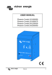
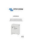
victron energie
USER MANUAL
GEBRUIKSAANWIJZING
GEBRAUCHSANWEISUNG
Victron Atlas Combi 12/800
victron energie
Subject to change without notice
2
AC04001E / 271095
user manual
victron energie
SECTIONS
ENGLISH
NEDERLANDS
DEUTSCH
victron energie
1
43
87
user manual
3
4
user manual
victron energie
ENGLISH
USER MANUAL
Victron Atlas Combi 12/800
victron energie
user manual
5
6
user manual
victron energie
INTRODUCTION
Victron Energie has established an international reputation as
a leading designer and manufacturer of power systems. Our
R&D department is the driving force behind this reputation as
it is continually seeking new ways of incorporating the latest
technology in our products. Each step forward results in
value-adding technical and economical features.
Our proven philosophy has resulted in a full range of
state-of-the-art equipment for the supply of electrical power
that meets the most stringent requirements.
Victron Energie systems provide you with high-quality AC
supplies in places where there are no permanent sources of
230-Volt AC power.
An automatic stand-alone power system can be created with a
configuration comprising a Victron Energie inverter, battery
charger, mains manager (if required) and, last but not least,
batteries with sufficient capacity.
Our equipment is suitable for countless situations in the field,
on ships or other places where a mobile 230-Volt AC power
supply is indispensable.
Victron Energie has the ideal power source for all kinds of
electrical appliances used for household, technical and
administrative purposes, including instruments susceptible to
interference. All of these applications require a high-quality
power supply in order to function properly.
Victron Atlas Combi 12/800
This manual contains directions for installing the Atlas
Combi model 12/800. It describes the functionality and
operation of the Atlas Combi, including its protective devices
and other technical features.
victron energie
user manual
7
8
user manual
victron energie
CONTENTS
1.
2.
DESCRIPTION
5
1.1
1.2
1.3
1.4
1.5
1.6
5
5
6
6
7
7
PROTECTIVE DEVICES
2.1
2.2
2.3
2.4
2.5
2.6
3.
13
13
13
Connection of temperature sensor
Battery temperatures of up to +10°C
Battery temperatures between
+10°C and +50°C
High battery temperature
13
14
INSTALLATION
15
4.1
4.2
4.3
4.4
15
15
15
16
16
16
16
17
18
18
19
Materials required for 230 V connections
Location
Battery cables
Connections
4.4.1 Earth
4.4.2 230 VAC output
4.4.3 230 VAC input
4.4.4 Battery
Starter battery
Jumpers, general
Potentiometers, general
START-UP
21
5.1
5.2
5.3
5.4
21
22
22
22
22
22
23
5.5
victron energie
9
9
10
11
11
11
COMPENSATED CHARGING
4.5
4.6
4.7
5.
Short-circuits
Maximum power
Overload
Temperature
Low input voltage
High input voltage
9
3.1
3.2
3.3
3.4
4.
General
Victron Atlas Combi
The battery charging section
The inverter section
Changeover
Charging
Operation
“On” position
“Auto” position
Changeover
5.4.1 Engaging 230 V mains
5.4.2 Disengaging 230 V mains
Charger
user manual
9
5.6
5.7
5.8
6.
7.
27
6.1
6.2
6.3
6.4
6.5
6.6
27
27
28
29
29
30
General
The inverter fails to start
The AC output voltage is too low
The battery charger does not start
The batteries overcharge
The batteries do not charge fully
SPECIFICATIONS
33
7.1
33
33
33
33
34
34
34
34
35
35
7.3
7.4
Inverter
7.1.1 Input
7.1.2 Output
7.1.3 Automatic Economy Switch (AES)
Battery charger
7.2.1 Input
7.2.2 Output
7.2.3 Changeover
General
Mechanical data
DRAWINGS
37
Complete energy system
Atlas Combi cabinet dimensions
Remote control connections
Atlas Combi connections
Position jumpers Atlas Combi
10
24
24
24
24
24
24
24
25
26
26
FAULT TRACING LIST
7.2
8.
Adjustments
5.6.1 Frequency
5.6.2 Output voltage
5.6.3 Switch-on sensitivity on “auto”
Battery charger
5.7.1 Maximum charging current
5.7.2 Adjustment of voltage
5.7.3 Float
5.7.4 Equalize
Maintenance
user manual
38
39
40
41
42
victron energie
1.
DESCRIPTION
1.1
General
Victron Atlas Combi 12/800 units are tested to ensure correct
functioning before leaving the factory. They are packed in
shock-absorbing polystyrene and packed in sturdy cardboard
boxes for secure transportation.
IP21=
protection against
materials larger
than 12 mm (for
example a finger)
and protection
against vertically
descending water-
The Victron Atlas Combi is housed in a robust aluminium
cabinet (IP21) suitable for floor or wall mounting. The AC
output terminals, the DC battery terminals and the terminals
for a remote control panel can be reached by opening the
front of the cabinet with a screwdriver.
1.2
Victron Atlas Combi
The Atlas Combi is a compact combination of an inverter and
an automatic battery charger, hence the name Atlas Combi.
The coding of the Combi models is composed as follows:
Watt =
unit of power
example:
Atlas Combi 12/800:
Volt =
unit of voltage
Volt
rms =
12 = 12 Volt, battery voltage
800 = 800 Watt, continuous power
root mean square
(effective value of
alternating wave)
Hertz =
unit of frequency
victron energie
user manual
11
The Atlas Combi delivers a trapezoidal alternating current of
230 V, 50 Hz. Continuous power can be delivered at all times.
A maximum short-duration power can be delivered for about
three seconds.
Almost any electric or electronic device powered by a
230 VAC (50 Hz) supply may be connected to the inverter of
the Atlas Combi.
1.3
The battery charging section
The battery charger of the Atlas Combi is suitable for a 230 V
(50 Hz) mains voltage. The charger works automatically and
delivers a maximum current of:
The batteries may remain permanently connected to the
charger, even during winter storage. The Atlas Combi is
suitable for starter batteries and semi-traction batteries of the
lead/acid type in open or sealed designs. A starter battery may
be connected to the second charger output. This charger can
charge a starter battery with a maximum current of 4 amp.
starter battery =
1.4
The inverter section
The inverter converts a direct current of 12 V into an
alternating current of 230 V, 50 Hz. With the Atlas Combi
switched on (i.e. switch set to “on”) the inverter’s own
no-load power consumption per model is:
a battery used
only to start
machines (such as
the engine of a
boat) and suitable
for high cold
currents
semitraction
battery =
A full-load efficiency of approximately 91% is achieved
through the use of FET transistors (see illustration 1).
The Atlas Combi has a “stand by” facility, as standard. It is
activated by setting the switch to the “auto” position. This
switches the inverter to a lower stand-by voltage at times
when the external equipment does not require power. This
limits power consumption to 2 Watt and the inverter operates
when a load is detected. Substantially reduced power
consumption is achieved when there are intermittent loads.
The sensitivity of the AES (Automatic Economy Switch) can
be adjusted, for more information see section 5 “Start-up”.
12
user manual
PCB =
Printed Circuit
Board
victron energie
The inverter is
furnished with a “Load
on inverter” LED. This
indicates that the
inverter voltage has
been switched to the
output.
1.5
intermittent
load =
a load regularly
switched on and
off automatically
in equipment such
as refrigerators or
electric heaters
with thermostats.
victron energie
Changeover
When a mains voltage
is connected to the
Atlas Combi, the
inverter is automatically
switched to mains after
about 10 seconds. This
changeover is indicated
by the yellow “load on
mains” LED (the “load
on inverter” LED goes
out) and the inverter is
immediately switched
off. More information
about this changeover is
given in section 5.4.
Illustration 1. No-load output voltage during “on” mode.
Illustration 2. No load output voltage
during “auto” mode.
user manual
13
1.6
Charging
The automatic part of the charger starts up about 5 seconds
after the charger switch has been set to the “on” position and
230 VAC is present.
Charging takes place according to the IUoUo characteristic
(see illustration 2).
AC =
12 V battery voltage
The charging current reaches a maximum at a battery voltage
of 12 V (see section 1.3). The standard settings for boost
charging voltage and float charging voltage are 14.25 V and
13.5 V respectively.
Alternating
Current.
DC =
Direct Current.
U (A)
12 Vdc
14,25
13,5
13
12
4 hours
30 sec.
time
I (A)
25
boost equalize float boost equalize
time
14
user manual
victron energie
2.
PROTECTIVE DEVICES
The Atlas Combi is extremely reliable thanks to
numerous built-in protective devices. Descriptions of these
devices are given below.
2.1
Short-circuits
With the Atlas Combi 12/800, inverter output (which is
protected against short-circuiting) amounts to 2.75 amp.
short circuit
current =
current supplied
when a shortcircuit on the output occurs.
In this condition the output voltage approaches 0 V. Once the
short-circuit has been rectified the inverter immediately
resumes normal operation. This eliminates the need to fit a
fuse in the inverter’s output circuit.
2.2
Maximum power
There is an upper limit to the power which the inverter can
deliver. This level, which is limited electronically, can be
delivered for 3 seconds.
Atlas Combi 12/800
2.3
continuous power
maximum-power
800 Watt
1500 Watt
Overload
If the inverter is subjected to a high load, it may reach the
critical limit (approx. 1000 Watt) and the overload protection
will be activated.
LED =
Light Emitting
Diode
victron energie
The overload protective device fitted to the Atlas Combi
12/800 works as follows:
❐
If the critical limit is reached, the red “overload” LED
lights up. After 3 seconds, the inverter limits the
power to ca. 1000 Watt.
❐
If the load drops below the critical limit within 3
seconds, the inverter continues working normally and
the “overload” LED goes out.
❐
When, after 3 seconds, the inverter has reached the
limit of its capacity and the load then drops below the
user manual
15
❐
critical limit, another 3 seconds must elapse before the
inverter again delivers full power.
If the inverter is overloaded for too long, the thermal
protection device will switch off the inverter after a
few minutes.
2.4
Temperature
The temperature of the electronics is measured continuously.
The inverter switches off before the temperature reaches an
unacceptably high level due to short-circuiting, overloading
or excessive ambient temperatures. The red “temperature”
LED lights up when this situation occurs. The inverter restarts
automatically once the temperature has dropped to an
acceptable level.
2.5
Low input voltage
DC voltage
delivered by
batteries
output voltage =
The inverter switches off if the input voltage is too low. This
input voltage limit is 10 V. The inverter restarts when this
voltage exceeds ±11 V.
2.6
input voltage =
AC voltage
delivered by the
Victron product
High input voltage
The inverter switches off if the input voltage is too high. The
inverter switches off if the input voltage rises above 17.3 V
and restarts once the input voltage has dropped below ±16.3 V.
The Atlas Combi 12/800 is NOT protected
against reversed polarity (i.e. “+” connected
to “-” and “-” connected to “+”). Accordingly,
please follow carefully the instructions
which are given in section 4.3.
16
user manual
victron energie
3.
COMPENSATED CHARGING
The Atlas Combi has a temperature
compensation facility which adjusts the charger voltage to the
battery temperature.
V.T.S. =
Victron
Temperature
Sensor
In order to use this facility, a temperature sensor (V.T.S.) must
be fitted to the battery. This is because a higher charging
voltage can be used with a cold battery than with a warm
battery. The reference charging voltage is 14.25 V at a battery
temperature of 20°C (see illustration 4).
3.1
Connection of temperature sensor
In order to connect the temperature sensor, jumper HDR6
must first be switched off (position “0"; see Drawings section,
drawing no. AC04013E, page 42). The temperature sensor is
operating when its yellow LED is lit up (for information on
jumpers, see section 4.6, ”Jumpers, general").
3.2
Battery temperatures of up to +10°C
At temperatures of up to +10°C, the charger supplies a
maximum charging voltage of 14.5 V. This output voltage is
limited because at higher voltages problems might occur in
the external equipment (see illustration 4, section “A”).
3.3
Battery temperatures between
+10°C and +50°C
In this temperature range, the output voltage is dependent on
battery temperature (as measured by the sensor). As the
temperature increases, the output voltage of the charger
decreases by 30 mV/°C (5 mV/°C per cell). (See illustration
4, section “B”).
victron energie
user manual
17
High battery temperature
At battery temperatures of +50°C and above,
the charging voltage drops sharply. At values
of 55°C and above, the charger operates as a
rectifier with an output voltage of 12 V (see
illustrations 4 and 5, sections “C” and “D”).
The plastic bag containing connection
materials includes instructions showing
where the temperature sensor must be fitted.
It is also necessary to change jumper HRD6
on the control PCB (see section “Drawings”,
drawing number AC04013E, page 42)
18
user manual
A
Volt (V)
3.4
B
C D
14
13
12
-20
-10
0
10
20
30
40
50
temp. ( oC)
Illustration 4. Temperature compensation while loading.
victron energie
4.
INSTALLATION
4.1
Materials required for 230 V
connections
❐
❐
❐
Two mains leads, 1.5 mm2, maximum length 6 m;
Screwdriver No. 1 (to connect the 230 V cables);
Open-end spanner M8.
4.2
Location
❐
Install the inverter in a dry area with good ventilation.
NOTE:
High ambient temperatures will reduce output power,
impair efficiency and shorten working life (see
“SPECIFICATIONS”).
There are holes in the bottom and rear of the cabinet
for floor or wall mounting. For the dimensions, refer
to section 8 “Drawings”, drawing number AC04015E,
page 39.
The Atlas Combi is suitable for mounting either on a
wall or on a horizontal surface. Ensure that there is
adequate ventilation, to allow for natural cooling. The
front of the Atlas Combi is detachable. Make sure you
will have easy access to the inside of the unit, from the
front, after installation.
Keep the distance between the Atlas Combi and the
battery(ies) as short as possible.
❐
❐
❐
4.3
Battery cables
The wire diameters of the battery cables are suitable for
continuous loads and peak loads.
Distances to the battery(ies)
cable diameter:
less than 1.5 m
25 mm2
more than 2.5 m but less than 4.0 m
35 mm2
more than 4.0 m but less than 6.0 m
50 mm2
Avoid contact resistances by tightening up all connections.
victron energie
user manual
19
4.4
Connections
4.4.1 Earth
Connect the mains earth wire to the earth
terminal of the AC terminal block. The circuit
is functional only if the cabinet is connected to
earth. An M4 earth screw is fitted in the
bottom of the cabinet. Connect the cabinet
earth terminal to earth. The earth for vessels is
the hull or earth plate; for motor vehicles it is
the chassis.
Illustration 5.
4.4.2 230 VAC output
The terminal block is located on the PCB.
The 230 V external equipment must be
connected to the inverter by means of a
three-wire cable (see illustration 7).
Use a cable with a flexible core and a wire
diameter of 1.5 mm2 to 2.5 mm2. The
connection arrangement of the output
terminal block is:
Phase:
Neutral:
Earth:
Brown or Black wire to: L1
Blue wire to:
N
Yellow/Green wire to:
PE
Illustration 6. Output vltage connections.
4.4.3 230 VAC input
A 230 VAC supply is needed if the Atlas
Combi’s battery charger is used. Use a
three-wire cable with a wire diameter of 1.5
to 2.5 mm2. The connection arrangement of
the input terminal block is in the same order
as the output terminal block (see illustration
8).
Illustration 7. Input voltage connections.
The inverter will be damaged if another alternating
current (e.g. from a generator) is connected to the
230 V output.
20
user manual
victron energie
output terminal
block =
output (delivery
230 Volt)
input terminal
block =
input (acceptance
230 Volt)
remote connections =
connections for
remote control
victron energie
4.4.4 Battery
The functioning and
working life of
equipment and batteries
depend on the battery
connections being
made correctly.
Between the battery
and the Atlas Combi
there is a circuit with a
Illustration 8. Battery connections.
low voltage and high
current. Resistance decreases accordingly as cables become
shorter and thicker. The combined resistance of the two
cables must not exceed 4 milliohms.
As previously explained (in section 2.6) the inverter is
not protected against reversed polarity. The following
procedure should therefore be used:
step 1
Unscrew the four screws on the front of the cabinet (1).
step 2
Carefully slide the front of the cabinet to one side.
-
+
victron energie
step 3
Satisfy yourself that the four fuses (30 ampere) have
been disconnected. You will find the fuses with the
other connection material. Connect-up the battery
cables; the “+” (red) to the right-hand connector and the
“-” to the connector on the left. If the connections have
been made properly, the green LED (“right”) will light
up.
user manual
21
step 4
If the red LED (“wrong”) lights up, this means that the
battery cables have been wrongly connected. In this
event, immediately disconnect the battery cables. Switch
the cables over, then reconnect them.
-
+
-
+
step 5
When the green LED “right” is lit up, the four 30
ampere fuses can be fitted. To this end, disconnect the
plus pole of the battery cable. Fit the fuses, then
reconnect the plus pole again.
step 6
Check that the connections have been sufficiently
tightened. Use the M8, open-end spanner.
4.5
Starter battery
Connect the starter battery to terminals 19 and 20 of the
“remote” terminal blocks (19 is the “+” and 20 is the “-” of
the battery). A wire thickness of 1.5 mm2 is sufficient for
connecting-up this battery.
Ensure that all switching between different 230 VAC
power supplies (e.g. shore generator) takes place
by means of DOUBLE-POLE switches. Otherwise
the Atlas Combi may be damaged.
4.6
double-pole
switching
switching by
means of a relay
which has two
separate contacts,
i.e. one for phase
and one for the
neutral wire
Jumpers, general
Jumpers are small removable connectors
situated on the PCB. By placing and
removing the jumpers various features can be
enabled or disabled.
Illustration 10 shows how to set the jumpers.
Illustration 10. Jumpers.
22
user manual
victron energie
4.7
Potentiometers, general
Potentiometers are adjustable resistors. Turning the screw
increases or reduces the values associated within the
potentiometer.
These values may concern matters
such as voltage, frequency or
switch-on sensitivity. The screw
must be turned by means of a
screwdriver (No. 0) and sealed with
Tipp-Ex or nail polish (see
illustration 11).
Illustration 9. Starter battery connections.
Illustration 11. Potentiometers
victron energie
user manual
23
24
user manual
victron energie
5.
START-UP
5.1
Operation
The switches and LEDs of the inverter are located on the
front of the Atlas Combi (see illustration 12).
inverter
on
auto
load on inverter
overload
high battery
low battery
temperature
description
= switched on
= automatic (AES)
= inverter switched to the output
= overload indication
= high input voltage
= low input voltage
= temperature indication
charger
on
load on mains
float
equalize/boost
description
= switched on
= load switched at input
= charging voltage for checking the battery
= charging voltage, once battery are fully
charged
= charger not functioning properly
failure
Illustration 12. Atlas Combi 12/800
frontpanel.
victron energie
user manual
25
5.2
“On” position
Start the inverter by setting the “inverter” switch to the “on”
position. The LEDs “on” and “load on inverter” light up if an
output voltage is present.
5.3
“Auto” position
When the inverter is in the “auto” mode (bottom position of
the switch), the yellow “auto” LED and the “load on inverter”
LED light up to indicate that the AES has been activated.
Refer to the fault tracing list if this does not occur. The
inverter starts as soon as the load at the output exceeds 9
Watt. The yellow “auto” LED goes out and the green “on”
LED lights up. The inverter switches back to the “auto” mode
automatically as soon as the load is switched off. The yellow
“auto” LED lights up again.
5.4
Changeover
5.4.1 Engaging 230 V mains
If the inverter is connected to the 230 V mains, the following
sequence of events will occur:
1. After about 10 seconds, the load is switched from the
inverter to the mains network. The yellow “load on mains”
LED lights up.
2. The inverter switches off. All LEDs go out.
3. The battery charger starts to operate:
4. The “on” LED lights up.
5. The “equalize/boost” LED lights up.
6. The charging capacity of the charger reaches a maximum
about 5 seconds after the “equalize/boost” LED lights up.
5.4.2 Disengaging 230 V mains
If the 230 V mains voltage is switched off, the following
sequence of events will occur:
1. The load is switched to the inverter.
2. The inverter starts immediately. The “load on inverter” and
“on” LEDs light up.
3. The external equipment is reconnected to a 230 V supply
within 1 second.
4. The “load on mains” LED goes out and the battery charger
is switched off.
26
user manual
victron energie
5.5
Charger
The charger of the Atlas Combi is switched on by setting the
“charger” switch to the “on” position. The “on” and
“equalize/boost” LEDs then light up.
The charging current starts to rise a few seconds after the
“on” and “equalize/boost” LEDs light up.
The voltage rises gradually, depending on battery capacity,
discharge and consumption.
When the battery reaches a voltage of 14.25 V, the charging
current drops.
This high charging current is maintained for four (or eight)
hours, producing optimum recharging of the batteries. After
this period the charger switches to a lower voltage of 13.5 V.
The “equalize/boost” LED is now off.
The battery charger works with the VDL 2-step charging
system made by Victron Energie. It automatically keeps the
battery in a perfectly charged condition for extended periods.
External equipment has immediate access to power.
V.D.L. =
Victron trickle
charge system
float charge
mode =
If, during the float charge cycle, the voltage drops below
13.5 V for longer than 30 seconds, a new boost charge cycle
is started. This may occur after the switching on of external
equipment which requires more than 30 amp. A new “boost equalize - float” cycle is also started if the charger is switched
off briefly.
recharging
boost charge
mode =
initial charging
victron energie
With the VDL system, the battery can remain permanently
connected to the battery charger, without overcharging
(gassing).
user manual
27
5.6
Adjustments
Open the cabinet by unscrewing the four outer screws on the
front, which is then removed. The adjustment points are on
the control PCB of the inverter. The PCB has six adjustment
points (see illustration 13).
5.6.1 Frequency
The frequency is set to a standard value of 50 Hz although
this can be altered by turning potentiometer P1 to the left
(“-”) or to the right (“+”). This can be measured with a digital
frequency meter. Please note that analog frequency meters
often give incorrect readings.
5.6.2 Output voltage
The output voltage is set to a standard value of 225 Vrms at a
load of continuous power and an input voltage of 12 V. The
unloaded output voltage is approximately 232 Vrms. The
output voltage may be adjusted by turning potentiometer P2
(top right) to the left (“-”) or to the right (“+”).
5.6.3 Switch-on sensitivity on “auto”
If the inverter fails to start when the external equipment
requests power, the AES sensitivity may be increased by
unscrewing the front PCB and turning potentiometer P5 (in
the centre of the PCB) to the right. Check whether the inverter
returns to “auto” once the external equipment has switched on.
5.7
Battery charger
5.7.1 Maximum charging current
The maximum charging current has been set to 30 amp by
means of potentiometer P6 (the one farthest to the right).
Measure this with a separate current meter. Switch on the
charger and apply a load that creates an output voltage of
12 V. Turn potentiometer P6 until the correct current has been
set. Seal the adjusting screw of potentiometer P6 with nail
polish or Tipp-Ex.
5.7.2 Adjustment of voltage
The battery charger operates with two charging voltages
which must be adjusted separately. First set the low charging
voltage (float) and then the high charging voltage (equalize).
28
user manual
victron energie
5.7.3 Float
The low charging voltage is adjustable by means of
potentiometer P4 (the one on the left). Switch on the charger
and disconnect all external equipment. Wait until recharging
has finished and the yellow “equalize/boost” LED has gone
out.
Connect a voltmeter with a reading accuracy of at least 0.1 V
to the output of the charger. Turn potentiometer R4 until the
correct voltage is set. Seal the adjusting screw of
potentiometer R4 with nail polish or Tipp-Ex.
Illustration 13. Location of
potentiometers on print.
victron energie
user manual
29
5.7.4 Equalize
The high charging voltage is adjustable by means of
potentiometer R3 (farthest left). Switch on the charger. Wait
until the batteries are charged to a level where the charging
current is below 5 amp. The yellow “equalize/boost” LED
should now light up. Connect a voltmeter with a reading
accuracy of at least 0.1 V to the output of the charger. Turn
potentiometer R3 until the correct voltage is set. Seal the
adjusting screw of potentiometer R3 with nail polish or
Tipp-Ex.
5.8
Maintenance
The Atlas Combi does not require any special maintenance. It
is advisable to check the electrical connections periodically
(once a year). Keep the converter as dry and clean as possible.
30
user manual
victron energie
6.
FAULT TRACING LIST
6.1
General
The following tables will facilitate the rapid tracing of the
most common types of faults.
For the checks to be carried out on the charger:
❐
Connect the mains supply to the charger.
❐
Disconnect all 12 V external equipment from the
batteries.
The fault tracing tables assume the following phenomena:
❐
the inverter does not start;
❐
the AC output voltage is too low;
❐
the charger does not start;
❐
The battery(ies) overcharge;
❐
The battery(ies) do not charge fully.
6.2
The inverter fails to start
step 1
Set the “inverter” switch to the “on” position and check
whether the green “on” LED lights up. Go to step 2.
step 2
The following may occur:
❐ The green “on” LED lights up and the Atlas Combi
produces only a “buzzing” noise; go to step 3.
❐ The green “on” LED lights up and the “overload”
LED lights up after a few seconds; go to step 3.
❐ The green “on” LED lights up and the “battery low”
LED lights up; go to step 4.
❐ The green “on” LED does not light up; go to step 8.
step 3
Remove the load from the AC output and check whether the
“overload” LED goes out when the inverter is switched on. If
it does not, go to step 8.
victron energie
user manual
31
step 4
Check the input voltage of the battery(ies) on the terminals of
the Atlas Combi. The input voltage of a 12 Volt battery
should lie between the following two values:
min. input voltage:
11 Volt
max. input voltage:
16 Volt
If the input voltage is not between the minimum and
maximum values, go to step 5. If the input voltage is correct,
go to step 7.
step 5
Check whether the 12 V connecting cables are properly
connected and the wires are of a sufficient diameter. Rectify
the situation if the connecting cables are not properly
connected or the wire diameters are not in conformity with
the specifications. If this action does not solve the problem,
go to step 6.
step 6
The batteries must be charged. Go to step 7 if the batteries
have been sufficiently charged or recharged but the inverter
does not start.
step 7
Check whether the plus (“+”) and minus (“-”) of the
battery(ies) and the Atlas Combi correspond. Go to step 8.
step 8
Contact your Victron Energie dealer to have the Atlas Combi
repaired.
6.3
The AC output voltage is too low
step 1
If you have determined with an RMS voltmeter (moving-iron
voltmeter) that the AC output voltage is too low, go to step 2.
step 2
Turn potentiometer P2 (see section 5 “Adjustments”) to the
right and check whether the voltage returns to the normal
value. If it does not, go to step 3.
step 3
Contact your Victron dealer to have the Atlas Combi repaired.
32
user manual
victron energie
6.4
The battery charger does not start
step 1
Turn on the charger by setting the “charger” switch to the
“on” position. If the “on”, “equalize/boost” and “current
amps” LEDs light up, proceed to section 6.6. If the LEDs of
the battery charging section fail to light up, go to step 2.
step 2
Turn off the 230 V mains supply. Check the ceramic fuse
(F7). This is located on the charger PCB in the cabinet. In
addition, use a voltmeter to check whether the input voltage
exceeds 200 Volt. If the fuse is intact, go to step 4. If the fuse
is defective, proceed to step 3.
step 3
Replace the defective fuse. Reconnect the 230 V mains
supply to the Atlas Combi. The problem has been solved if
the fuse operates normally. If it becomes defective again, go
to step 4.
step 4
Contact your Victron Energie dealer to have the Atlas Combi
repaired.
6.5
The batteries overcharge
step 1
Check the battery voltage when the “equalize” LED lights up.
Go to step 2.
step 2
If the battery voltage is about 14.25 V on a 12 V battery(ies),
contact the manufacturer of the battery because the battery is
probably defective. If so the battery(ies) must be replaced. If
the voltage is higher than the above values, go to step 3.
step 3
Check the jumpers on the charger PCB. They are located to
the left on the inside of the door. For normal usage, jumpers
HDR 1, 2, 4 and 6 are switched on, jumper HDR 5 is
switched off and HDR 3 is in the left-hand position (see
section 8, drawing number AC04013E on page 42 If this is
the case, go to step 4.
victron energie
user manual
33
step 4
Contact your Victron dealer to have the Atlas Combi repaired.
6.6
The batteries do not charge fully
step 1
Check whether the cables to the batteries are properly
connected to the cable terminals. Repair these connections if
the contacts are defective. If this does not solve the problem,
go to step 2.
step 2
Check the mains voltage at the input of the Atlas Combi. If it
is higher than 200 VAC, go to step 3. If it is lower than
200 VAC, go to section 6.3.
step 3
Allow the Atlas Combi to charge continuously for about eight
hours with the 12 V external equipment switched off. The
problem has been solved if after this period the 12 V batteries
have values of about 14.25 V. If the values are lower, go to
step 4.
step 4
Check whether too many pieces of external equipment are
connected to the Atlas Combi and check the batteries for:
❐ defective cell(s);
❐ a maximum capacity of 300 a.h.
❐ If the batteries are in proper working order, go to step
6. Any battery(ies) not meeting the specifications,
must be replaced. After replacement, go to step 5.
step 5
Check the charger again. The problem has been solved if the
charger works properly. If it does not, go to step 6.
step 6
Contact your Victron dealer to have the Atlas Combi repaired.
step 7
Check the mains supply or generator supply for the correct
voltage, drops of voltage in lines, excessively long cables, etc.
If necessary consult the manufacturer of the item(s)
concerned.
34
user manual
victron energie
7.
SPECIFICATIONS
7.1
Inverter
7.1.1 Input
+
-
Nominal input voltage:
Input voltage range:
Switch-on voltage:
Switch-off voltage:
Voltage ripple:
Nominal input current:
Maximum input current:
No-load in “auto” mode:
No-load in “on” mode:
Input fuses
12 VDC
10 -17.25 VDC
11 VDC
10 VDC
maximum 5% RMS
80 amp
150 amp
2 Watt
7.5 Watt
4 x 30 Amp (carfuse)
7.1.2 Output
Output voltage:
Frequency:
Waveform of output voltage:
Power factor:
Power at 20°C:
Power at 30°C:
Switch-on behaviour:
230 VAC + 5%
50 Hz; + 1 Hz
Trapezoidal
0.9 capacitive to 0.4 inductive
800 Watt, power factor 1
700 Watt, power factor 1
The inverter can start under any
load conditions. The nominal
output voltage is reached in 50
msec.
7.1.3 Automatic Economy Switch (AES)
Switch-on:
Adjustable sensitivity:
Switch-off:
Test voltage on “auto”:
Efficiency:
Dynamic stability:
victron energie
user manual
9.5 Watt
2 - 48 Watt
4.5 Watt
65 Vrms 50 Hz
91% (maximum)
Maximum surges of 10% when
switching on and off at 50%
nominal load. Recovery time is
1/2 period.
35
Overload protection:
Short-circuit protection:
Ambient temperature protection:
High/low input voltage
protection:
7.2
The delivered power is limited
electronically to: 185% (12 Volt
battery) of the continuous power at
the nominal input voltage.
The output is short-circuit proof.
The short-circuit current is 2.75
Arms.
Sensors measure the temperature
of critical components. The
sensors switch off the inverter if
the temperature on the FETs rises
above 75°C and/or the transformer
temperature rises above 140°C.
The inverter restarts automatically
after the components have cooled
down.
The inverter switches off
automatically at values above
17.25 VDC and below 10 VDC.
Battery charger
7.2.1 Input
Nominal input voltage:
Frequency:
Input voltage range:
Input voltage fuse 230/240 V:
Power factor:
230 VAC
47 - 63 Hz
10%
1 x 10 amp slow; 5 x 20 mm
0.7 inductive
7.2.2 Output
Nominal charging voltage:
Boost charging voltage:
Float charging voltage:
Charging characteristic:
Voltage stability:
Output current:
Trickle charge fuse
36
+
12 VDC
14.25 VDC
13.5 VDC
IUoUo according to DIN 41772
1%
30 amp
15 Amp (car fuse)
user manual
-
victron energie
7.2.3 Changeover
Maximum switching capacity:
Changeover time:
Changeover delay:
Protective device:
7.3
2300 Watt
0.1 sec.
ca. 10 seconds
ceramic fuse, 10 amp slow; 5 x
20 mm
General
EMC:
Electro-magnetic compatability according Council Directive
89/336 EEC
Emission
EN 55014 (1993)
EN 60555-2 (1986)
Immunity
EN 50082-1 (1991)
7.4
Mechanical data
Noise level:
Cabinet:
Protection:
Colour:
Dimensions (H x W x D):
Weight:
Connecting points:
Output
Output/input 12 VAC:
Trickle charger:
Input:
Earth
Cooling:
Relative humidity:
victron energie
user manual
40 dB(A)
Aluminium, resistant to seawater
IP21
Blue (RAL 5012), epoxy
350 x 250 x 213 mm
16,5 kg
230 VAC terminals (2.5 mm2)
M8 screws
230 VAC terminals (2.5 mm2)
M4 screw
Natural cooling
95% (maximum)
37
38
user manual
victron energie
8.
DRAWINGS
victron energie
Complete Victron Energy System
38
Atlas Combi 12/800 cabinet dimensions
39
Remote control connections
40
Atlas Combi 12/800 connections
41
Position jumpers Atlas Combi 12/800
42
user manual
39
victron energie
starter batteries
engine
Victron
Atlas Combi
service batteries
220 V generator
VICTRON MAINS MANAGER
victron energie
12 V dc
on-board
systeem
Victron
Mains Manager
net
washing machine
40
user manual
micro wave
lighting
victron energie
250
25
200
205
25
8
294
348
31
23
6.5 mm
150
8.0 mm
25
230
© victron energie b.v.
victron energie
Victron Atlas Combi 12/800 dimensions
user manual
41
42
user manual
victron energie
victron energie
user manual
43
44
user manual
victron energie