1
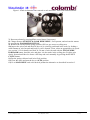
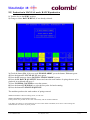
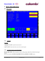
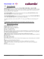
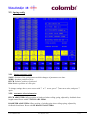
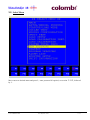
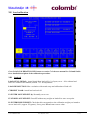
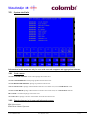
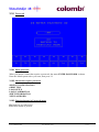
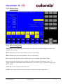
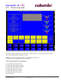
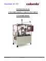
SYSTEM MANUAL
COLOMBI SPRING COILING MACHINE
COLOMBI ORBIT
Saldovägen 9B
S-175 62 Järfälla Sweden
Tel:+46(0)8/795 27 30
Fax:+46(0)8/761 08 03
1 off 29
35107001
1
START OF THE SYSTEM
1.1
1.2
2
3
POWER UP AND PREPARE FOR PRODUCTION
S TARTUP MENU
3
3
PRODUCTION ALTERNATIVES
2.1
2.2
2.3
3
5
PRODUCTION IN AUTO MODE
PRODUCTION IN MANUAL MODE, BATCH PRODUCTION
PARKING THE COILER
MENU DESCRIPTIONS
9
3.1
MAIN MENU
3.1.1
Load info
3.1.2
Automatic length control information
3.1.3
Spring receipt information
3.1.4
Status indicators
3.1.5
OK
3.1.6
Function buttons in main menu
3.2 COILER TEST
3.2.1
Manual coiling positions
3.2.2
Manual coiling speeds
3.2.3
Function buttons in coiler test
3.3 S PRING CONFIG
3.3.1
Spring parameter table
3.3.2
Automatic offset information
3.3.3
Function buttons in spring config menu
3.4 O RBIT TEST
3.4.1
Heater info
3.4.2
Load info
3.4.3
Status indicators
3.4.4
Function buttons in Orbit test menu
3.5 S ELECT MENU
3.6 LOAD SETUP
3.6.1
Load info
3.6.2
Function buttons in Load setup menu
3.7 LOAD CALIBRATION INFO
3.7.1
Function buttons in Load calibration info menu
3.8 LOAD CALIBRATION
3.8.1
Load cell
3.8.2
Function buttons in Load calibration menu
3.9 S YSTEM TOTAL INFO
3.9.1
Total counter
3.9.2
Function buttons in System total information menu
3.10 PASSWORD
3.10.1
Enter password
3.10.2
Menus that require password
3.10.3
Function buttons in Password menu
3.11 NEW PASSWORD
3.11.1
Set new password
3.11.2
Function buttons in New password menu
3.12 DIATEST MENU
3.12.1
Diatest settings in mm
3.12.2
Diatest status indicator
3.12.3
Automatic offset information
3.12.4
Function buttons in Diatest menu
Saldovägen 9B
S-175 62 Järfälla Sweden
6
7
8
Tel:+46(0)8/795 27 30
Fax:+46(0)8/761 08 03
9
9
9
10
10
10
10
11
11
12
12
13
13
13
14
15
15
15
16
16
17
18
18
19
20
20
21
21
22
23
23
23
24
24
24
24
25
25
25
26
26
27
27
27
2 off 29
35107001
1 START OF THE SYSTEM
1.1 Power up and prepare for production
To change menu, press F8 SELECT MENU and use ? ?or ? ?to move cursor to desired menu, then
press ? ?, enter password if required, followed by ? . For further details see menu descriptions in
section 3.
1.2 Startup menu
1) Turn on the main power switch on the side of the machine.
2) Press the blue ENABLE button on the panel and the air pressure will be activated.
3) Wait for the system to boot properly, showing a blue menu, possibly hidden behind some error
messages.
4) Turn the key to the SERV position.
5) Open front doors.
6) Turn the pitch tool and coiling pin cams counter-clockwise to their respective
zero-positions. Figure 1.
Saldovägen 9B
S-175 62 Järfälla Sweden
Tel:+46(0)8/795 27 30
Fax:+46(0)8/761 08 03
3 off 29
35107001
Figure 1. Notch in diameter cam centered to axle and roller. Pitch cam centered similar.
7) Reset any alarms by pressing F16 (several times if necessary).
8) Change menu to STARTUP & LOAD WIRE MENU, if not present, and activate the motors
by pressing the F14 HOMING BUTTON.
9) Remove the fixed position spring collector (PP1) to get access to coiling area.
10) Inspect the wire track and check if the wire is correctly positioned in the tools, by feeding a
small amount of wire forward and look if a coil is formed. If not, select an appropriate wire speed
(see section 3.2.2 for details) and feed 30–50 mm of wire forward with the F2 JOG WIRE
FORWARD button, bend the wire and place it in the tracks in the coiling pins. Feed the wire
slowly forward until the wire forms a full loop and cut it manually by pressing the F5 CUT
CYCLE button.
11) Put the spring collector back in its fixed position.
12) Close the doors and turn the key to AUTO position.
13) Go to MAIN MENU and select desired production alternative as described in section 2.
Saldovägen 9B
S-175 62 Järfälla Sweden
Tel:+46(0)8/795 27 30
Fax:+46(0)8/761 08 03
4 off 29
35107001
2 PRODUCTION ALTERNATIVES
The spring coiling machine can be run either from the control panel or, in AUTO mode, with an
external start signal to the user interface connector that also provides a ready signal when a spring is
in position to be delivered, and an error signal if anything is wrong in the coiling system.
To change menu, press F8 and use ? ?or ? ?to move cursor to desired menu, then press ? ?and enter
password, followed by ? if required. For further details about the different menus see menu
descriptions in section 3 of this manual.
Saldovägen 9B
S-175 62 Järfälla Sweden
Tel:+46(0)8/795 27 30
Fax:+46(0)8/761 08 03
5 off 29
35107001
2.1 Production in AUTO mode
1) Check that all doors are closed.
2) Turn the key to the AUTO position.
3) Change to menu MAIN MENU, if not already selected.
4) Press the button F1 CYCLE ON, F1 turns green.
5) Check the button F2, if the text reads AUTO, press the button, F2 turns green and the text
AUTO MODE appears in the status indicator.
6) The text MACHINE READY appears in the status indicator.
7) There is a green light on top of the machine that indicates ready status.
The machine is now ready to receive external signals.
When a signal is received from the user interface, one spring is delivered and the coiler produces
one spring. The next signal starts over again with one spring delivered and one produced etc.
Saldovägen 9B
S-175 62 Järfälla Sweden
Tel:+46(0)8/795 27 30
Fax:+46(0)8/761 08 03
6 off 29
35107001
2.2 Production in MANUAL mode, BATCH production
1) Turn the key to the SERV position.
2) Change to menu BATCH MENU, if not already selected.
3) Check the button F14, if the text reads ENABLE ORBIT, press the button, F14 turns green.
4) Press the button F1 CYCLE ON, F1 turns green.
5) Press the F3 button to choose BATCH if SINGLE MODE is preset.
6) Press the F4 BATCH QUANTITY button and enter the total number of springs that are to be
produced in each batch and press ? .
7) Press F12 ZERO COUNTER to reset the counter.
8) Press the button F5 IPP2 POS to select delivery tube for batch running.
9) Press the button F2 START SEQUENCE.
The machine produces the total number of springs entered.
ORBIT ENABLED: Orbit in working mode, set with F14.
ORBIT DISABLED: Orbit disabled with F14.
In this position is it possible to run coiler continuously with F6 START COILER.
CAUTION: No alarms or control functions are active when Orbit is disabled; do not leave coiler running and
unattended for more than very short periods.
Saldovägen 9B
S-175 62 Järfälla Sweden
Tel:+46(0)8/795 27 30
Fax:+46(0)8/761 08 03
7 off 29
35107001
2.3 Parking the coiler
This operation is mainly used before shutting the main power off to ensure a safe position of the
coiler tools.
1) In MAIN MENU the production can be interrupted by pressing the F1 button. Ongoing spring
production is stopped when the most recent spring is coiled, but not cut.
2) Now press F6 PARK; the servomotors return to their home positions.
3) The coiler pins move apart, the pitch tool goes down, a few millimeters of wire are fed forward
and the power to the servo motors is disabled.
4) The text COILER IS PARKED is shown on the display.
5) To restart, press F6 UNPARK.
6) The power to the servo motors is enabled, the coiler pins move inwards, the pitch tool moves up
and the wire is fed forward.
7) Turn key to SERV position and open the doors.
8) Remove the fixed position spring collector (PP1) to get access to coiling area.
9) Change menu to STARTUP & LOAD WIRE MENU and cut the wire by pressing F5. Check
that the wire is correctly positioned in the tools, otherwise follow parts 9-11 in section 1.2
9) Put the spring collector back in its fixed position.
10) Select a production mode as described in sections 2.1 to 2.2.
Saldovägen 9B
S-175 62 Järfälla Sweden
Tel:+46(0)8/795 27 30
Fax:+46(0)8/761 08 03
8 off 29
35107001
3 MENU DESCRIPTIONS
3.1 Main menu
3.1.1 Load info
Load info
CURRENT VALUE: Actual load on load cell.
LAST VALUE: Latest load value sent to the control system.
3.1.2 Automatic length control information
PITCH ADJUSTED : Offset of pitch tool when coiling spring, adjusted by feedback from length
control.
Reset can be made in COILING MACHINE TEST and SPRING CONFIG menus.
Saldovägen 9B
S-175 62 Järfälla Sweden
Tel:+46(0)8/795 27 30
Fax:+46(0)8/761 08 03
9 off 29
35107001
3.1.3 Spring receipt information
ACTUAL SPRING NR: Spring configuration selected in SPRING CONFIG menu.
3.1.4 Status indicators
AUTO MODE: Auto mode selected and machine is controlled from customer interface if
MACHINE READY and ORBIT ENABLED.
MACHINE NOT READY: Cycle off or machines not ready if in AUTO MODE
MACHINE READY: Machine ready to deliver springs in AUTO MODE.
COILER IS PARKED: Servomotors moved to absolute zero position after pressing F6 PARK
COILER.
COILER PARK DISABLED : servomotors moved to working position with F6 DISABLE
PARK.
KEY IN POS 1: Key in SERV position, machine not able to run in AUTO MODE.
CAUTION: No alarms or control functions are active when orbit is disabled; do not leave
coiler running and unattended for more than very short periods.
3.1.5 OK
Press cycle on/off to continue : Appears after stops caused by alarms.
3.1.6 Function buttons in main menu
F1: ON prepares for spring delivery, OFF stops machine at end of cycle.
F2: Toggles man/auto mode.
F3: Set allowed rejects percentage for totally made springs.
F4: Set allowed rejects percentage for the last 100 made springs.
F6: Parks / unparks coiler (See 2.3).
F8: Menu select.
F10: Reset counters.
F11: Reset actual total reject %.
F12: Resets actual last 100 reject %.
F14: If pressed before F1 CYCLE ON, resets Orbit and stops when ready to deliver a
spring in good spring eject.
Saldovägen 9B
S-175 62 Järfälla Sweden
Tel:+46(0)8/795 27 30
Fax:+46(0)8/761 08 03
10 off 29
35107001
3.2 Coiler test
Accessing this menu puts machine in CYCLE OFF mode.
3.2.1 Manual coiling positions
WIRE POSITION: Moved with F1 JOG WIRE FORWARD and F9 JOG WIRE
BACKWARD, zero counter with F4 ZERO WIRE. Can be used to determine the length of wire
needed to get a certain number of coils at a certain diameter.
PITCH POSITION: Actual position of pitch tool, adjusted with F2 JOG PITCH UP and F10
JOG PITCH DOWN. Position only valid in this menu but can be used to determine the
appropriate start/lower position for the pitch tool related to the coil, to be used in SPRING
CONFIG menu.
DIAMETER POSITION: Actual position of coiler pins, adjusted with F3 JOG DIAMETER IN
and F11 JOG DIAMETER OUT. Position only valid in this menu but can be used to get an
approximate value for the desired coil diameter, to be used in SPRING CONFIG menu.
Saldovägen 9B
S-175 62 Järfälla Sweden
Tel:+46(0)8/795 27 30
Fax:+46(0)8/761 08 03
11 off 29
35107001
3.2.2 Manual coiling speeds
JOG WIRE SPEED: Speed when using F1 JOG WIRE FORWARD or F9 JOG WIRE
BACKWARD for manual wire feed. A speed of 50-200 mm/s is recommended to retread or change
the wire. Higher speeds, up to 3000 mm/s are used to check the quality of the coil when the wire is
properly positioned in the coiling tools.
JOG PITCH SPEED: Speed of pitch tool movement when using F2 JOG PITCH UP or F10
JOG PITCH DOWN for manual pitch adjustment.
JOG DIAMETER SPEED: Speed of coiler pins movement when using F3 JOG DIAMETER IN
or F11 JOG DIAMETER OUT for manual diameter adjustment.
To change speeds above, move cursor with ?? or ? arrow, press ? ?enter new value and press ?
again.?
CAUTION! Be careful with manual wire feed at higher speeds and open doors.
3.2.3 Function buttons in coiler test
F1/F9: Manual wire feed.
F2/F10: Manual pitch tool adjustment.
F3/F11: Manual coiling pins adjustment.
F4: Zero wire position value.
F5: Make a complete cut cycle.
F6: Set motors position, used to set motors for pitch and diameter to zero position when cams are to
be mounted or checked. Pressing once moves motor to zero position and once more to run position.
F7: Zeros automatically adjusted pitch.
NOTE: When pressing F7 spring may be out of range, regarding the free length.
Spring should be adjusted so that the pitch adjust is close to zero when correct springs are produced
F8: Select menu.
F12: Toggle mandrel in/out.
F13: Toggle cutter up/down.
F14: Homing button, used to activate motors after emergency stop or when main power is switched
on.
F15: Zeros automatically adjusted diameter.
NOTE: When pressing F15 spring may be out of range, regarding the outer diameter.
Spring should be adjusted so that the diameter adjust is close to zero when correct springs are
produced
F16: Resets alarms if present.
Saldovägen 9B
S-175 62 Järfälla Sweden
Tel:+46(0)8/795 27 30
Fax:+46(0)8/761 08 03
12 off 29
35107001
3.3 Spring config
3.3.1 Spring parameter table
ZONE: Sections of the spring between which changes of parameters are done.
WIRE: Absolute position on wire.
PITCH: Relative position of pitch tool.
DIA: Relative position of coiler pins.
To change settings above, move cursor with ? or ? arrow, press ? ?
, enter new value, and press ?
again.
3.3.2 Automatic offset information
PITCH ADJUSTED: Offset position of pitch tool when coiling spring, adjusted by feedback from
length control. Reset with F7 PITCH ADJ. ZERO.
DIAMETER ADJUSTED: Offset position of winding pins when coiling spring, adjusted by
feedback from diatest. Reset with F6 DIATEST ADJ. ZERO.
Saldovägen 9B
S-175 62 Järfälla Sweden
Tel:+46(0)8/795 27 30
Fax:+46(0)8/761 08 03
13 off 29
35107001
3.3.3 Function buttons in spring config menu
F1: Makes a test spring with actual parameters. Status indicator, described in section 3.1.4, in
MAIN MENU must be “OK” and key in SERV position.
F2: Deletes all values in zone table. If pressed by mistake, press F3 LOAD DATA to restore data
from memory.
F3: Loads parameters from memory for actual spring nr. Make sure that the right spring is selected
with F14 ACTUAL SPRING.
F4: Saves present parameters to memory for actual spring nr. Make sure that the right spring is
selected with F14 ACTUAL SPRING.
Must be pressed before any springs with new parameters can be produced outside this menu.
F6: Resets automatic diatest adjustment value.
F7: Resets automatic pitch adjustment value.
F8: Select menu
F9: End zone in zone table. Must be the same as the last zone containing data in zone table.
F10: Wire speed for actual spring.
F11: Wire length for actual spring. Must be the same as wire value in the last zone containing data
in zone table.
F12: Manually entered offset position of the pitch tool. Normally not used for permanent
adjustment of spring length.
F13: Manually entered offset position of the coiler pins. Normally not used for permanent
adjustment of diameter.
F14: Select spring receipt. F3 LOAD DATA is then used to load parameters for selected spring
from memory.
F16: Resets alarms if present.
Saldovägen 9B
S-175 62 Järfälla Sweden
Tel:+46(0)8/795 27 30
Fax:+46(0)8/761 08 03
14 off 29
35107001
3.4 Orbit test
Accessing this menu puts machine in cycle off mode.
Key must be in SERV position to enable use of some functions.
NOTE: After having returned to the menu MAIN MENU from ORBIT TEST and pressing the
button F1 CYCLE ON, ORBIT resets itself by emptying all of the revolver test sockets of springs
through the outlet for faulty springs. The revolver is then filled until two approved springs are in the
delivery position.
3.4.1 Heater info
HEATER
F3: Sets current for the heater.
3.4.2 Load info
LOAD
CURRENT VALUE: Actual load on load cell.
Saldovägen 9B
S-175 62 Järfälla Sweden
Tel:+46(0)8/795 27 30
Fax:+46(0)8/761 08 03
15 off 29
35107001
3.4.3 Status indicators
3.4.4 Function buttons in Orbit test menu
F1: Makes one test spring.
F2: Moves Orbit nest one position.
F3: Sets current for the heater.
F4:
F5:
F6:
F8: Select menu.
F9:
F10: Slides Orbit head up/down.
F11:.Heats spring in nest, if Orbit head is down.
F13: Opens diatest for spring eject.
F14: Resets load value.
F15: Eject spring in diatest.
F16: Resets alarms if present.
Saldovägen 9B
S-175 62 Järfälla Sweden
Tel:+46(0)8/795 27 30
Fax:+46(0)8/761 08 03
16 off 29
35107001
3.5 Select Menu
Move cursor to desired menu and press ? , enter password if required, see section 3.11.2, followed
by ? .
Saldovägen 9B
S-175 62 Järfälla Sweden
Tel:+46(0)8/795 27 30
Fax:+46(0)8/761 08 03
17 off 29
35107001
3.6 Load setup
3.6.1 Load info
CURRENT LOAD: Actual load on load cell.
F9 NOMINAL WEIGHT: Desired spring force for spring.
F10 TOLERANCE +: Maximum force tolerance for spring, force outside this value rejects
measured spring.
F11 TOLERANCE -: Minimum force tolerance for spring, force outside this value rejects
measured spring.
F12 ZERO LOAD: Tares load cell, if pressed with a spring in position over load cell.
Saldovägen 9B
S-175 62 Järfälla Sweden
Tel:+46(0)8/795 27 30
Fax:+46(0)8/761 08 03
18 off 29
35107001
3.6.2 Function buttons in Load setup menu
F8: Select menu
F9: Load nominal weight
F10: Load + tolerance
F11: Load – tolerance
F12: Tare or zero load
Saldovägen 9B
S-175 62 Järfälla Sweden
Tel:+46(0)8/795 27 30
Fax:+46(0)8/761 08 03
19 off 29
35107001
3.7 Load calibration info
This procedure is also described in section 7 of the user manual for Colombi Orbit.
3.7.1 Function buttons in Load calibration info menu
F8: Select menu.
Saldovägen 9B
S-175 62 Järfälla Sweden
Tel:+46(0)8/795 27 30
Fax:+46(0)8/761 08 03
20 off 29
35107001
3.8 Load calibration
Go to LOAD CALIBRATION INFO menu or section 7 of the user manual for Colombi Orbit
for a detailed description of the calibration procedure.
3.8.1 Load cell
LOAD-CELL SIGNAL: Actual signal from load cell in % of span, set to ~10% without load.
Refer to Colombi Orbit manual, section 7.2.1 for adjustment.
LOAD RESOLUTION: Max. resolution with actual setup and calibration of load cell.
CURRENT LOAD: Actual load on load cell.
F4 ENTER LOW WEIGHT (0): Normally set to zero.
F5 STORE LOW WEIGHT: Press F5 without any weight on loadcell to store zero point.
F6 ENTER HIGH WEIGHT: Check that this corresponds to the calibration weight you intend to
use on load cell 1 (approx 250 grams), if not, press F6 and enter correct value.
Saldovägen 9B
S-175 62 Järfälla Sweden
Tel:+46(0)8/795 27 30
Fax:+46(0)8/761 08 03
21 off 29
35107001
F7 STORE HIGH WEIGHT: Press F7 with calibration weight on load cell to store high weight.
3.8.2 Function buttons in Load calibration menu
F1: Zero load.
F4: Press without any weight on load cell.
F5: Value of weight used for calibration of load cell.
F6: Press with calibration weight on load cell.
F8: Select menu.
Saldovägen 9B
S-175 62 Järfälla Sweden
Tel:+46(0)8/795 27 30
Fax:+46(0)8/761 08 03
22 off 29
35107001
3.9
System total info
Information in this menu can only be reset with external computer and appropriate software.
3.9.1 Total counter
TOTAL COILED SPRINGS: Total coiled springs since latest reset.
TOTAL GOOD SPRINGS: Good springs produced since latest reset.
TOTAL REJECTED SPRINGS: Springs rejected since latest reset.
TOTAL LOAD LOW: Springs with load below tolerance since latest reset, set in LOAD SETUP menu.
TOTAL LOAD HIGH: Springs with load above tolerance since latest reset, set in LOAD SETUP menu.
HEAT FAIL: Not heated springs since latest reset.
NO CONTACT: Springs to short to reach heater electrode since latest reset
3.9.2 Function buttons in System total information menu
F8: Select menu.
F16: Reset alarms if present.
Saldovägen 9B
S-175 62 Järfälla Sweden
Tel:+46(0)8/795 27 30
Fax:+46(0)8/761 08 03
23 off 29
35107001
3.10 Password
3.10.1 Enter password
When you choose a menu that requires a password, the menu ENTER PASSWORD is shown.
Enter the default password or your own, then press ? ?
3.10.2 Menus that require password
SPRING CONFIGURATION
ORBIT TEST
LOAD SETUP
LOAD CALIBRATION
SHIFT INFORMATION
NEW PASSWORD
3.10.3 Function buttons in Password menu
F8: Return to previous menu.
F16: Reset alarms if present.
Saldovägen 9B
S-175 62 Järfälla Sweden
Tel:+46(0)8/795 27 30
Fax:+46(0)8/761 08 03
24 off 29
35107001
3.11 New password
3.11.1 Set new password
Press F1, enter new password, one to four digits, press ?
Press F2, repeat new password, press ?
3.11.2 Function buttons in New password menu
F1: First input of new password.
F2: Second input of new password.
F8: Return to previous menu.
F16: Reset alarms if present
Saldovägen 9B
S-175 62 Järfälla Sweden
Tel:+46(0)8/795 27 30
Fax:+46(0)8/761 08 03
25 off 29
35107001
3.12 Diatest menu
3.12.1 Diatest settings in mm
NOMINAL: Preferred diameter from diameter test. This value can differ slightly from the final
diameter of the spring.
MAX: Maximum deviation from nominal value for actual spring.
MIN: Minimum deviation from nominal value for actual spring.
HI: Accepted max deviation from nominal value before automatic adjustment is done.
LO: Accepted max deviation from nominal value before automatic adjustment is done. To
change settings for values above, move cursor with ? or ? arrows, press ? ?enter new value, and
press ? again.
ACTUAL: Actual reading from diameter test.
LAST: Latest value sent to the control system for automatic diameter adjustment.
Saldovägen 9B
S-175 62 Järfälla Sweden
Tel:+46(0)8/795 27 30
Fax:+46(0)8/761 08 03
26 off 29
35107001
3.12.2 Diatest status indicator
DIATEST OFF: Diameter test disabled with F2.
DIATEST ON: Diameter test enabled with F2.
3.12.3 Automatic offset information
ACTUAL SPRING: Spring configuration selected in SPRING CONFIG menu.
PITCH ADJUSTED: Offset position of pitch tool when coiling spring, adjusted by feedback from
length control. Reset with F4 PITCH 1 ADJ. ZERO.
DIAMETER ADJUSTED: Offset position of coiler pins adjusted by feedback from diameter test.
Reset with F3 DIATEST ADJ. ZERO.
3.12.4 Function buttons in Diatest menu
F1: Diatest zero. Sets actual position of diameter test to zero.
F2: Diatest on/off (choice)
F3: Diatest adjust zero
F4: Pitch adjust zero
F5: Diatest check /up. Moves diameter test down/up.
F6: Save data (save diatest settings).
F7: Diatest calibration. Remove spring from diameter test and then press button for calibration.
F8: Select menu
F13: Opens diatest for eject
F15: Ejects spring from diatest.
F16: Reset alarms if present.
Saldovägen 9B
S-175 62 Järfälla Sweden
Tel:+46(0)8/795 27 30
Fax:+46(0)8/761 08 03
27 off 29
35107001
3.13
Booster setup menu
The basic principal of the timers, F1 and F12, are that the time set is the time that will run from a
tube sensor signal until the sequence is ready.
All delivery boosters and pulse timers can be modified in this menu.
See Delivery setup documents for factory settings.
3.13.1 Function buttons in Setup menu
F1: Good Eject time from Orbit.
F2: Eject time from Diatest to Orbit.
F3: Eject time from Coiler to Diatest.
F4: Eject time from Ch I to Line.
F5: Eject time from Ch 2 to Line.
F6: Eject time from Ch 3 to Line.
F7: Eject time from Ch 4 to Line.
F8: Select menu.
Saldovägen 9B
S-175 62 Järfälla Sweden
Tel:+46(0)8/795 27 30
Fax:+46(0)8/761 08 03
28 off 29
35107001
F9: Eject time bad spring out.
F12 Positions IPP4 to ch 1.
F13 Positions IPP4 to ch 2.
F14 Positions IPP4 to ch 3.
F15 Positions IPP4 to ch 4.
Saldovägen 9B
S-175 62 Järfälla Sweden
Tel:+46(0)8/795 27 30
Fax:+46(0)8/761 08 03
29 off 29
35107001