1
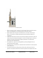
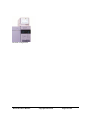
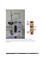
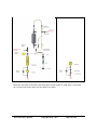
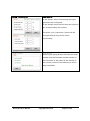
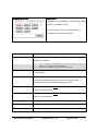
User Manual DVLS Liquefied Gas Injector Series 2 Date: 8/26/2014 v5.0 Table of Contents 1 ABOUT DA VINCI LABORATORY S OLUTIONS ..................................................... 4 2 US E OF THE US ER MANUAL ................................................................................ 5 3 S AFETY AND REGULATORY INFORMATION ....................................................... 6 4 5 6 3.1 GENERAL..............................................................................................................................6 3.2 LPG ....................................................................................................................................7 3.3 TRAINING AND USAGE ...........................................................................................................7 3.4 INJECTOR..............................................................................................................................7 3.5 PRESSURE STATION ................................................................................................................8 3.6 CONTROLLER ........................................................................................................................9 3.7 GAS CHROMATOGRAPH .........................................................................................................9 3.8 SYMBOLS .............................................................................................................................9 INTRODUCTION ................................................................................................. 10 4.1 SAMPLE INTRODUCTION VIA GASOLINE DIRECT INJECTION (GDI) ...............................................10 4.2 INJECTOR............................................................................................................................11 4.3 PRESSURE STATION ..............................................................................................................12 4.4 CONTROLLER ......................................................................................................................14 OPERATING INS TRUCTIONS .............................................................................. 16 5.1 PREPARING THE GC .............................................................................................................16 5.2 PREPARING THE PRESSURE STATION .......................................................................................16 5.3 PREPARING THE CONTROLLER................................................................................................20 5.4 SAMPLE ANALYSIS ...............................................................................................................23 APPLICATION 1: RES IDUE IN LPG ..................................................................... 27 6.1 BACKGROUND ....................................................................................................................27 6.2 LGI CONTROLLER SETTINGS...................................................................................................27 6.3 GC CONFIGURATION ............................................................................................................28 6.4 COLUMN INSTALLATION PROCEDURE ......................................................................................30 6.5 CHROMATOGRAM ...............................................................................................................31 6.6 INTEGRATION ......................................................................................................................31 6.7 CALIBRATION ......................................................................................................................32 6.8 CALCULATION OF UNKNOWN SAMPLES ...................................................................................33 DVLS LGI 2 User Manual Copyright 2014 – v5.0 Page 2 of 45 6.9 7 CALCULATION OF THE RECOVERY OF THE MINERAL OIL FRACTION ...............................................34 US ER MAINTENANCE ........................................................................................ 35 7.1 GENERAL............................................................................................................................35 7.2 PERIODIC MAINTENANCE ......................................................................................................35 7.3 NEEDLE REPLACEMENT .........................................................................................................37 8 S PARES AND CONS UMABLES ........................................................................... 39 9 TROUBLES HOOTING .......................................................................................... 41 DVLS LGI 2 User Manual Copyright 2014 v5.0 Page 3 of 45 1 About Da Vinci Laboratory Solutions As a versatile partner for analytical applications and authorized distributor of worldleading instrument manufacturers Da Vinci Laboratory Solutions (DVLS) is able to provide an expert advice and offers an extensive range of chromatographic systems, software, services and supplies. For information visit: www.davinci-ls.com or contact us at: Da Vinci Laboratory Solutions Cairostraat 10 3047 BC Rotterdam, The Netherlands Postbus 12103 3004 GC Rotterdam, The Netherlands T: +31-(0)10 258 1870 F: +31-(0)10 258 1879 E: [email protected] Note: In no event will Da Vinci Laboratory Solutions be liable for any loss or damage including incidental, indirect, special or consequential damages arising from the use of DVLS Liquefied Gas Injector. Note: Information, descriptions and specifications in this publication are subject to change without notice. DVLS LGI 2 User Manual Copyright 2014 – v5.0 Page 4 of 45 2 Use of the User Manual This guide is intended for users of the Da Vinci Liquefied Gas Injector (LGI). It describes the routine operational procedures of the LGI. The information in this guide not only applies to operation of the LGI, but contains information on the use of the LGI in certain applications as well, for instance residue analysis in LPG. Additionally, using the LGI with other sample matrices not described in this manual, e.g. Butadiene or Condensate, will require certain modifications to the instrument. Details on the use of the Gas Chromatograph (GC) and data acquisition software is not described in this document, but available from the manufacturer’s manuals. Note: There are several important safety notices to keep in mind when using the LGI, as described in Chapter 3. Note: Make sure you have read and understood all safety information before starting to use the instruments. Da Vinci does not hold liability for any (personal) damage that is caused by (the use) of the LGI. Note: For extra information which may not be found in this guide, we refer to the Da Vinci website or your local Da Vinci representative. DVLS LGI 2 User Manual Copyright 2014 v5.0 Page 5 of 45 3 Safety and regulatory information 3.1 General These instruments are designed to pressurize extremely flammable liquefied gasses and highly flammable volatile liquids and to inject an amount of this sample under pressure in an analyzer. Working with pressurized and highly / extremely flammable liquids holds certain risks. Read and use the following safety instructions. Potential dangerous voltages can exist on: All LGI and GC electronic boards and electrical connections All LGI and GC AC power supplies and electrical connections All electronic boards and connections are shielded by covers. Unless specifically instructed to, never remove the cover. Contact your Da Vinci service representative for assistance and instructions. Note: Note: Warning: Warning: Note: It is not allowed to make changes to the instruments or setup without consulting Da Vinci Laboratory Solutions B.V. All information in this manual applies to set up of the instrument for analysis of LPG. Use of the instrument in a manner not specified by the manufacturer or use for another application than described in this manual may result in a safety hazard. If parts are substituted, or unauthorized modifications are performed, this may result in a safety hazard. Using the LGI with other sample matrices than LPG, e.g. Butadiene or Condensate, will require certain modifications to the instrument for safe operation. Always wear safety glasses during operation of the LGI. DVLS LGI 2 User Manual Copyright 2014 – v5.0 Page 6 of 45 3.2 LPG LPG is a flammable mixture; all safety precautions must be taken. If the LGI is used for LPG injection, please refer to the following international guidelines: ASTM D1265: Practice for Sampling Liquefied Petroleum (LP) Gases. LPG Material Safety Data Sheet, usually to be obtained from the LPG supplier. 3.3 Training and Usage The LGI should be used by trained users only. Perform cleaning and maintenance as described in the chapter on Maintenance. Refer to qualified service personnel for servicing. Use of the instrument in a manner not specified by the manufacturer or use for another application than described in this manual may result in a safety hazard. If parts are substituted, or unauthorized modifications are performed, this may result in a safety hazard. 3.4 Injector The Injector has moving parts and a needle. These instructions must be followed: Wear safety glasses while operating the LGI. Turn off the power before removing the Injector tower or during maintenance. The needle is sharp. Never open the Cover when the Injector is in operation. When the instrument is unattended, never leave the needle in the Ex Needle position. Make sure the needle is in the needle waste vessel by Initialization via the Controller. Initialization is performed by pressing the Init button in the Diagnose screen (please refer to the operational chapter for details on the Controller). The Injector can be stopped at any time by pressing the red button on the Controller. All electronic wires and connections are shielded by covers. Only trained and authorized personnel are allowed to open the covers. DVLS LGI 2 User Manual Copyright 2014 v5.0 Page 7 of 45 3.5 Pressure Station Wear safety glasses while operating the Pressure Station. Never leave the LGI instrument unattended while the sample cylinder is installed and under pressure. Ensure the pressure rating for the sample cylinder, cylinder valves and quick connector of your choice (the choice of quick connector usually depends on the company standard) will withstand the factory set 35 bar / 507 psi pressure at which the pressure relief valve is installed. Never use a charging pressure higher than 25 bar / 363 psi, unless the Pressure Station is specifically set up for a higher maximum pressure. Read the pressure on the Pressure Station gauge when the cylinder with liquid gas is opened and make sure this pressure is maintained after closing the flow. A drop in pressure may be an indication of a leak in the flow system. Open the sample cylinder only to supply high pressure Nitrogen, to purge and to inject the sample. Close the cylinder immediately after purging and injection. Refer to the manufacturer’s manual for specific details on the quick connectors. Do not use the Pressure Station for anything outside the scope of the validated application. Note: Note: Warning: Never try to disconnect quick connectors if the system is still under pressure. The Nitrogen pressure must be released first. The Pressure Station must be connected to protective earth using the protective earth on the back of the Pressure Station. Always connect the earth clamp to the sample cylinder to prevent build up of static electricity. DVLS LGI 2 User Manual Copyright 2014 – v5.0 Page 8 of 45 3.6 Controller Power sockets must be fused with min. 16A and all power sockets must have protective earth. Never replace the power cord with another type. The Injector can be stopped at any time by using the red button on the Controller. All electronic boards and wires are shielded by covers. Only trained and authorized personnel is allowed to open the covers. 3.7 Gas Chromatograph Please refer to the GC manufacturer’s manual. 3.8 Symbols Warnings in the manual or on the instrument must be observed during all phases of operation, service, and repair of this instrument. Failure to comply with these precautions violates safety standards of design and the intended use of the instrument. Da Vinci holds no liability for the customer’s failure to comply with these standards. See accompanying instructions for more information. Crush hazard: keep hands clear. Hot surface. Earth (ground) terminal. DVLS LGI 2 User Manual Copyright 2014 v5.0 Page 9 of 45 4 Introduction 4.1 Sample introduction via Gasoline Direct Injection (GDI) The (liquefied) sample introduction principle used in the LGI is based on the Gasoline Direct Injector (GDI) technique commonly used in car engines. The GDI is filled with sample under pressure. After activation of the solenoid, the sample is injected through a needle either to waste (to purge), or to a GC column for analysis. Injection cycle of the GDI (a) The GDI is filled with the liquid sample under pressure. (b) After activation of the solenoid, the sample is pushed through the needle. (c) After injection, the position returns to start position. A complete LGI system consists of: The Injector which is the injection device that holds the GDI The Pressure Station The Controller DVLS LGI 2 User Manual Copyright 2014 – v5.0 Page 10 of 45 The combination of the Injector, Pressure Station and Controller is, hereafter, referred to as the Liquefied Gas Injector (LGI). Complete LGI application Residue in LPG analysis via GC is a proved application where the LGI is used, as described in subsequent chapters. The required GC configuration (column, inlet, detector etc.) used may vary depending on the analysis needed. 4.2 Injector The Injector consists of the GDI mounted in a housing, a stepper motor for movement of the GDO and a waste vessel. The Injector is placed on top of a GC using a specific mounting post. The stepper motor moves the GDI into position either for injection or purge to waste. A needle is attached to the GDI, allowing injection into a GC. The sample flows from the Pressure Station into the GDI. The function of the waste vessel is to collect the sample that comes out of the needle during needle rinsing. The sample is disposed via tubing attached to the DVLS LGI 2 User Manual Copyright 2014 v5.0 Page 11 of 45 waste vessel. The sample -either liquid or vapour- coming out of this tubing should be disposed appropriately. When the Injector is initialised via the Controller, the needle moves initially to the waste vessel. After activation of the GDI, the sample is pushed in discrete bursts through the needle, initially to waste but in a later stage to the GC inlet. Injector 4.3 Pressure Station For a representative analysis, the sample must remain in the liquid phase during the injection process, this is especially required for LPG or other chemicals that are gaseous at ambient pressures. To keep the sample under pressure, a device is used that adds high pressure Nitrogen to the sample cylinder and controls the outlet pressure and flow. This device is referred to as the Pres sure S tation. Two types of Pressure Stations are available: PTS 2 and PTS 3. In PTS2, the flow is controlled via a needle valve. In PTS3, the flow is controlled via a vaporizer. DVLS LGI 2 User Manual Copyright 2014 – v5.0 Page 12 of 45 Pressure Station type PTS2 with sample cylinder When the sample cylinder is opened, the liquid sample flows through the Pressure Station and subsequently to the GDI and back to the Pressure Station. Waste sample leaves the system via the Waste exit on the back of the Pressure Station, connected to a suitable waste system (see the Installation Manual for suggestions). In PTS2 the needle valve is the part until where the sample is pressurized. After the needle valve pressure becomes atmospheric and the LPG liquid vapors. In PTS3, the vaporizer is the part until where the sample is pressurized. The LPG liquid is vaporized by the heated vaporizer. The needle valve / vaporizer can be bypassed by opening the Bypass Switch, to quickly release leftover sample. The sample flow is controlled via a rotameter which also allows for visual inspection of the sample flow. The Pressure Station has a safety pressure relieve valve which opens when the pressure in the system exceeds the set maximum pressure (for example 35 bar / 507 DVLS LGI 2 User Manual Copyright 2014 v5.0 Page 13 of 45 psi), to make sure the pressure does not exceed the maximum pressure of the rotameter. Details on the function and operation of the Pressure Station switches, connections, needle valve (PTS2) and vaporizer (PTS3) are described in the operational chapter of this manual. 4.4 Controller The Controller unit contains the electronics to control the GDI and to start the GC. In some applications a GC valve is programmed as well. The Controller is operated via a touch screen, except for the start- and stop buttons. The stop button on the Controller immediately stops the Injector operation if required. Details on the various Controller commands are described in the operational chapter of this manual. Rinse pulse 400 ms Rinse cycles 10 Rinse interval 2s Vent 8s Inject pulse GDI 50 ms Inject pre-delay 1s Inject post-delay 2s Typical Controller settings DVLS LGI 2 User Manual Copyright 2014 – v5.0 Page 14 of 45 Controller on Agilent GC DVLS LGI 2 User Manual Copyright 2014 v5.0 Page 15 of 45 5 Operating instructions Note: In case of an emergency or in case pressure, flow or temperature readings are different from normal operation, first make sure the sample cylinder is closed. To stop the LGI immediately: push the red stop at the front panel of the Controller. Note: Always wear safety glasses! 5.1 Preparing the GC Using your GC data acquisition system, download the required GC set points. If required, start one or more blank analysis by starting the GC directly without the LGI, in order to clean the GC columns prior to injection. The signal is considered stable when the start and end signal value (pA) of two consecutive blank runs are within 5% deviation. An unstable baseline can be caused by a leak, detector gases, or by high boiling point components not completely eluted from the columns. In general, the signal height at the end of a calibration, validation or routine sample run should be similar to signal from a blank run. Refer to the Application chapter or the GC manufacturer’s manual for specific GC details. 5.2 Preparing the Pressure Station For PTS3 (Pressure Station type 3, with vaporizer): switch on the vaporizer by inserting the Pressure Station power cord into the socket. Allow the vaporizer to heat up for several hours (the vaporizer can be left on overnight and is usually only turned off when the system is not used for a longer period of time). Familiarize with the Pressure Station parts, as described on the next pages. DVLS LGI 2 User Manual Copyright 2014 – v5.0 Page 16 of 45 Depres s urize valv e Flex ible hos e Needle v alv e On / Off S w itch Pres s ure S am ple Input Quick Connector Pres s ure Flow m eter By pas s By pas s Needle v alv e Vaporizer Complete front view of PTS3 (left): in PTS3 flow is controlled via a vaporizer Front view of the flow controlling part of PTS2 (right): in PTS2 flow is controlled via a needle valve DVLS LGI 2 User Manual Copyright 2014 v5.0 Page 17 of 45 Schematic overview of PTS3 (left): in PTS3 flow is controlled via a vaporizer. Schematic overview of the flow controlling part of PTS2 (right): in PTS2 flow is controlled via a needle valve (other parts are the same as for PTS3). DVLS LGI 2 User Manual Copyright 2014 – v5.0 Page 18 of 45 S am ple Input Quick Connection for sample cylinder. Connect Flex ible hose 1) Supplies high pressure Nitrogen to the sample cylinder. Connection to the Sample cylinder with quick connect. 2) Can be directly connected to the Sample Input Quick Connect for rinsing Pressure Station and injection needle with Nitrogen. Press ure S w itch Opens the high pressure Nitrogen supply to the Flexible hose Vaporizer (PTS3 only) 1) Sample flow control 2) Heats and vaporizes the sample. The LPG sample is pressurized and in liquid phase until the vaporizer. After the vaporizer the sample becomes atmospheric and is directed to waste. Needle v alv e & 1) Sample flow control. Needle v alv e On / 2) The LPG sample is pressurized and in liquid phase until the Off S w itch (PTS2 only) vaporizer. After the needle valve, where pressure becomes atmospheric, the LPG liquid vapors and is directed to waste. Flow m eter 1) Rotameter type flow meter for flow control. 2) Allows visual inspection of the sample flow. Depres surize v alv e Opening this valve releases the Nitrogen Pressure from the Flexible hose. Note: Note: Note: Note: By pass S w itch Before opening the Depressurize valve, make sure the valves of the sample cylinder and the Pressure switch are closed. Always make sure that the Depressurize valve is closed after the Depressurization is finished. If the Depressurize valve is left open and Nitrogen Pressure is applied for removing the sample waste from the Pressure Station, then (part of) the sample waste will be forced via the Depressurize valve into the Flexible hose. This sample will not be disposed via the waste exit, but is blown out via the Flexible hose into the surrounding area. If the previous sample is not completely removed from the Pressure Station and a new sample cylinder is pressurized with Nitrogen Pressure while the Depressurize valve is open, then the previous sample is forced via the Flexible hose into the sample cylinder. The needle valve / vaporizer can be bypassed by opening the Bypass Switch, to quickly release leftover sample. DVLS LGI 2 User Manual Copyright 2014 v5.0 Page 19 of 45 5.3 Preparing the Controller Prepare the Controller as follows: Put the power plug into the socket. Switch on the Controller by pressing the On / Off switch on the back. Familiarize with the Controller screens, as described on the next pages. Load the typical Controller settings for your application. S tartup s creen: Com ments : By pressing the [Accept] button, the user is asked to confirm to study the manual before starting to operate the LGI system. Main s creen: Com ments : This is the default Controller screen which will show after initialization. It shows the actual status of the Injector, GC and vent valve controlled by the LGI (if applicable). The values between brackets are the values entered in the Setup screens. Selecting the [Rinse N] button will immediate start the rinsing process (N times) according to the setup details entered. DVLS LGI 2 User Manual Copyright 2014 – v5.0 Page 20 of 45 S etup 1&2 s creens : Com ments : In the Setup 1 menu rinse settings and inject pulse time are configured. In the Setup 2 menu the vent time and injection pre- and post-delay are entered. The pulse, cycle, interval etc. figures can be changed directly using touch-screen functionality. Help S creen: Com ments : Selecting the [Help] button will show the serial number and the firmware and GUI version of the Controller. It also refers to the manual; in the current version of the software no online help is available. DVLS LGI 2 User Manual Copyright 2014 v5.0 Page 21 of 45 Diagnose s creen: Com ments Diagnostics are available by selecting the [Diag] button on the Main screen. The functionality of the various buttons is described in the following table. Button Functionality [Ex Needle] Will bring the GDI in a position above the waste vessel to replace the needle. Note: Note: [Init] Never put the GDI in the [Ex Needle] position when sample (under pressure) is present in the Pressure Station and Injector. Always return the GDI to the [Init] position afterwards. Will bring the GDI to its initial and default position (needle in waste vessel). [Ex GDI] Will bring the GDI in a position in which the connections on the Y-piece can be easily accessed. E.g. to leach check these connections and to enable exchanging the GDI. [GDI] Will open the GDI valve once according to the Inject pulse GDI [setup 1] configuration. [Rinse 1] Will open the GDI valve once according to the Rinse pulse GDI [setup 1] configuration. [Vent] Will manually switch the vent valve (if present). [Beep] Switches on and of the touch sound of the Controller buttons. [GC-Start] Starts the GC program without starting the Injector. DVLS LGI 2 User Manual Copyright 2014 – v5.0 Page 22 of 45 5.4 Sample analysis 5.4.1 Configuration (if required) Using the Controller [setup 1] menu: 1. Set the Rinse pulse to 400 ms. 2. Set the Rinse cycle to 10. 3. Set the Rinse interval to 2 s. 5.4.2 Cleaning and depressurization prior to injection On the Pressure Station: 1. Connect the Flexible hose to the Sample Input Quick connector and turn the Pressure switch On (if not already). 2. Establish a rotameter flow of approx. 20-40 ml/min by turning the needle valve (PST2) or vaporizer (PST3). In case of PST2, make sure the needle valve On / Off switch is in the On position. 3. Allow approximately 5 minutes rinsing with Nitrogen. 4. Rinse the needle with Nitrogen by selecting the [Rinse N] button. 5. Turn the Pressure switch Off. 6. Turn the Bypass switch On. 7. Wait until the pressure gauge reads 0 bar / psi. 8. Turn the Bypass switch Off. 9. Verify that the pressure gauge remains 0 bar / psi, wait if necessary. 10. Verify that the rotameter flow reads 0. 5.4.3 Sample analysis On the Pressure Station: 1. After the pressure and the rotameter flow have dropped to 0, remove the Flexible hose from the Sample Input Quick connector. 2. Install the sample cylinder on the Sample Input quick connector. 3. Install the earth clamp on the cylinder (not on the cylinder valves, Quick connectors or eventual adapter pieces, but on the cylinder itself). DVLS LGI 2 User Manual Copyright 2014 v5.0 Page 23 of 45 Cylinder with earth clamp. Note: Install the earth clamp not on the cylinder valves / quick connect or eventual adapter pieces, but ON THE CYLINDER ITSELF! 4. Connect the Flexible hose to the top of the cylinder. 5. Verify that the Depressurize valve is closed (on top of the Pressure Station). 6. Close the flow Controller (needle valve / vaporizer) completely. 7. Turn the Pressure switch On. 8. Open the top valve of the cylinder. 9. Open the bottom valve of the cylinder. Now the Pressure Station will fill with gas and subsequently liquid, which is observed at the rotameter. 10. Slowly open the flow Controller (needle valve / vaporizer) to establish a flow of 5-10 ml/min. Purge the system for 1-2 minutes. During the purging, time select the [Rinse N] button. Note: The accuracy of the actual flow reading is depending on the type of Controller used. On some models it can be difficult to establish a stable flow of 5-10 ml/min. Use a lower flow set point, but longer time in this case. 11. Close the flow Controller completely. 12. After the rotameter ball has dropped to 0, select the [Rinse N] button. 13. Repeat 2 times with intervals of 10 seconds. 14. After the last rinse cycle, wait for 10 seconds and press the [Start] button on the Controller. 15. After injection, close the bottom valve of the cylinder 16. Close the top valve of the cylinder 17. Turn the Pressure switch Off. DVLS LGI 2 User Manual Copyright 2014 – v5.0 Page 24 of 45 18. Release the Nitrogen pressure by opening the Depressurize valve (on top of the Pressure Station). Wait for 5 seconds, then close the Depressurize valve again. Note: Note: Note: Note: Before opening the Depressurize valve, make sure the valves of the sample cylinder and the Pressure switch are closed. Always make sure that the Depressurize valve is closed after the Depressurization is finished. If the Depressurize valve is left open and Nitrogen Pressure is applied for removing the sample waste from the Pressure Station, then (part of) the sample waste will be forced via the Depressurize valve into the Flexible hose. This sample will not be disposed via the waste exit, but is blown out via the Flexible hose into the surrounding area. If the previous sample is not completely removed from the Pressure Station and a new sample cylinder is pressurized with Nitrogen Pressure while the Depressurize valve is open, then the previous sample is forced via the Flexible hose into the sample cylinder. 19. Release the sample pressure by turning the Bypass valve On. When the pressure has dropped to 0, turn the bypass valve Off and open the flow controller (needle valve / vaporizer). In case of PST2, make sure the Needle valve On / Off switch is in the On position. 20. Wait until the pressure and rotameter flow have completely dropped to zero. This may take a few minutes depending on the type of sample injected. 21. Disconnect the Flexible hose, remove the earth clamp and remove the cylinder. 22. Close the flow controller (needle valve / vaporizer). In case of PST2, make sure the needle valve On / Off switch is in the Off position. 5.4.4 Standby preparation 1. Follow the Cleaning and depressurization procedure described in paragraph 5.4.2. 2. After depressurization leave the Flexible hose connected to the Sample Input Quick connector to avoid dust / particles will enter this Quick Connector. 5.4.5 Additional pentane rinsing procedure If the sample contains high concentrations of heavier hydrocarbons, amines or other strong absorbing components it is recommended to test for carry over in between analyses using pentane cylinders. In such cases these steps should be followed: 1. Clean and prepare a sample cylinder with pentane. 2. Analyze the pentane according to the procedure under 5.4.3. DVLS LGI 2 User Manual Copyright 2014 v5.0 Page 25 of 45 Note: Carry out an additional rinsing sequence prior to injection [Rinse N]. 3. If memory of components of interest is visible in the chromatogram, repeat steps 1-2 until the system is clean. Note: In case the LGI system is not only used for injection of liquefied gasses, but also for injection of fluids that are in the liquid phase at atmospheric pressure, beside vapor, also liquid sample will elute from the Waste exit. As a consequence, care should be taken that the waste lines (Pressure Station waste and Injector waste) remove the liquid efficiently and quickly so that no accumulation of liquid occurs. If it is expected that accumulation of liquid will occur, the customer should make a facility to safely remove the liquid. For suggestions of how to connect the waste exit to different waste facilities, refer to the LGI Installation Manual. DVLS LGI 2 User Manual Copyright 2014 – v5.0 Page 26 of 45 6 Application 1: Residue in LPG 6.1 Background Control over the residue content is essential in end-use applications of automotive LPG. These residues can lead to troublesome deposits that will accumulate and corrode or plug the LPG fuel filter, the low pressure regulators, the fuel mixer or the control solenoids. LPG can become contaminated by oily residues during its production or transport. Transport contamination can come from shared pipelines, valves and trucks used for the distribution of other products. Production sources such as the desulfurization process may contribute sulphur absorbent oil to the LPG stream. 6.2 LGI Controller settings The following table shows the typical Controller settings for the Residue in LPG analysis under the conditions described in Chapter 6.3. Rinse pulse 400 ms Rinse cycles 10 Rinse interval 2s Vent 8s Inject pulse GDI 50 ms Inject pre-delay 1s Inject post-delay 2s DVLS LGI 2 User Manual Copyright 2014 v5.0 Page 27 of 45 6.3 GC configuration For residue analysis, the GC is equipped with an On-Column Inlet and solvent vent. The sample is injected on a 5 m coated stainless steel capillary. This retention gap is connected to a 3 m non polar retaining column, which is routed to the solvent vent for flushing the LPG light ends. Subsequently, the vent is closed and the flow is switched to the non-polar analytical column for residue separation by boiling point. DVE-01716 S tainles s Steel Tubing OD 1/16” ID 1.0 m m S S -100-6 1/16 S w agelok S S union DVE-095196 S ulfinert tubing 20 cm, 0.53 mm ID DVE-001818 LGI S ilFlow Wafer DVE-095196 S ulfinert tubing 5 m, 0.53 mm ID Schematic configuration of GC columns and connectors for residue analysis of LPG Tubing to v ent Analy tical column Pre column Pre column Retention gap LGI SilFlow Wafer configuration DVLS LGI 2 User Manual Copyright 2014 – v5.0 Page 28 of 45 Oven initial temp: 35 °C Inlet initial temp: 55 °C Oven initial time: 3 min. Inlet initial time: 3 min. Oven rate: 25 °C/min. Inlet rate: 25 °C/min. Oven final temp: 325 °C Inlet final temp: 325 °C Oven final time: 20 min. Inlet final time: 20 min. Detector Air flow: 350 ml/min. Detector Hydorogen 35 ml/min. flow: Detector make-up flow: 20 ml/min. Detector temp: 325 °C Pressure mode: Constant flow Column Flow: 6 ml/min. Septum purge flow: 12 ml/min. Vent flow (vent valve >40 ml/min. On) Purge flow (vent valve <1 ml/min. Off) Retention gap: Sulfinert® coated SS capillary 5m x 0.53 mm ID Pre-column: MXT-5, 3 m x 0.32 mm ID x 1.00 µm film thickness Analytical column: MXT-5, 27 m x 0.32 mm ID x 1.00 µm film thickness Split bracket-union Sulfinert® coated SS capillary 15 cm x 0.53 mm ID tubing: Union-vent valve Stainless steel, OD 1/16”, ID 1.0 mm tubing: Residue in LPG application: Typical Chromatographic parameters DVLS LGI 2 User Manual Copyright 2014 v5.0 Page 29 of 45 6.4 Column installation procedure 1. Connect all columns according to Figure 25 and 26. In general, it is important to make a clean, straight cut on the column. Most GC suppliers have ceramic cleaving wedges or other specific capillary column cutters available. After installing the column nut and ferrule on the column, cut the column and inspect the top of the column using a magnifier: Secondary, verify that an LGI needle smoothly fits in the column without any obstruction, straighten the column if required. Install the column in the GC inlet according to the manufacturer’s manual. If the Agilent Cool on Column inlet is used, insert the column until the spring is completely compressed. Slightly tighten the column nut. Mark the column and pull down the column 6 to 7 mm. Tighten the column nut further. More information on the column connection can be found in the Troubleshooting chapter of the User Manual. DVLS LGI 2 User Manual Copyright 2014 – v5.0 Page 30 of 45 For a leak tight connection of the Sulfinert tubing to the 1/16” Swagelok union (part. no. SS-100-6), replace one of the stainless steel ferrules of the union by a 0.53 mm SilTite™ ferrule (part. no. DVE-029797). For tightening use the procedure described in paragraph 5.1 for connection of the bleed capillary to the vent valve. 2. Allow at least 30 minutes of flushing of the columns with carrier gas before oven heat is applied. 3. Condition the columns according to the manufacturer’s instructions. 6.5 Chromatogram The chromatography should look like the chromatogram shown below. Verify whether the solvent peak is separated from the C10, the first component of the total of the residue. Example chromatogram of 50 ppm residue in LPG. 6.6 Integration Integrate the total area between C10 and C40. Refer to the data acquisition software manufacturer’s manual for details on total area integration. DVLS LGI 2 User Manual Copyright 2014 v5.0 Page 31 of 45 6.7 Calibration N-Alkane standard Determine the retention time of C10 and C40 by analyzing an LPG standard spiked with C10 and C40, or by analyzing a dedicated Alkane standard mixed with pentane. C10 is the first component to be determined as residue. LPG calibration standard Analyze an LPG standard with a matrix close to the matrix of the unknown samples. The recommended concentration of the mineral oil is 50 ppm. The response factor can be calculated with the following formula: Rf conc area where: Rf = Response factor Conc = Concentration of mineral oil in LPG Area = Summed area of C10-C40, after subtraction of a blank Pentane validation sample A mixture of mineral oil in pentane is a good validation standard. Several concentrations can be prepared. It is recommended to fill a clean sample cylinder with the standard and inject under equal conditions as to regular LPG samples. Note: In case the LGI system is not only used for injection of liquefied gasses, but also for injection of fluids that are in the liquid phase at atmospheric pressure, beside vapor, also liquid sample will elute from the Waste exit. As a consequence, care should be taken that the waste lines (Pressure Station waste and Injector waste) remove the liquid efficiently and quickly so that no accumulation of liquid occurs. If it is expected that accumulation of liquid will occur, the customer should make a facility to safely remove the liquid. For suggestions of how to connect the waste exit to different waste facilities, refer to the LGI Installation Manual. DVLS LGI 2 User Manual Copyright 2014 – v5.0 Page 32 of 45 6.8 Calculation of unknown samples Calculate the concentration of residue in the validation standard or the unknown sample as follows: Note: If the matrix of the calibration sample (e.g. pentane) is different from the unknown sample, a density correction should be applied according to ASTM D 7756. DVLS LGI 2 User Manual Copyright 2014 v5.0 Page 33 of 45 Concentrat ion area * Rf where: Concentration = Mineral oil content in ppm weight Area = Summed area of the area of C10-C40, after subtraction of the blank Rf = Concentration of the mineral oil in the calibration gas divided by the area. 6.9 Calculation of the recovery of the mineral oil fraction To maintain a quality control chart for this application it is recommended to monitor the recovery of the validation standard over time. The optimum recovery is 100%. Mineral Oil content in LPG in ppm weight= ppm theoretical/ppm measured*100% where: ppm theoretical = the recorded weight of mineral oil ppm measured = the result of the chromatographic analysis DVLS LGI 2 User Manual Copyright 2014 – v5.0 Page 34 of 45 7 User Maintenance 7.1 General Note: Before performing any maintenance, first check the instrument’s safety guidelines, and make sure the system is purged and in standby position. 7.2 Periodic maintenance The following table describes the recommended actions required to ensure good performance of the LGI application. For GC routine maintenance please refer to the GC manufacturer’s manuals. To prevent carry-over from previous samples it is recommended to purge the instrument with Nitrogen when the system is in standby. Note: Note: Before performing maintenance items marked with *): switch off the Controller and remove the power plug from the socket. Before performing maintenance items marked with **): remove the power plug of the Pressure Station from the socket (applies only to PST3; PST2 does not have any electrical power connections), switch off the Controller and remove the power plug of the Controller from the socket. DVLS LGI 2 User Manual Copyright 2014 v5.0 Page 35 of 45 Frequency Description Daily/Weekly Verify the pressure level of the supply gases to the instrument. Replace with new cylinders if required. Run a control sample and apply statistical quality control procedures. The exact frequency of the control sample depends on internal guidelines and on the average number of routine samples. Monthly Replace the septum of the GC inlet. Perform a leak check on the column connections inside the GC oven. Perform a leak check of the Pressure Station and Injector as described in the Installation Manual. Verify there is no abnormal pressure drop (monitor the pressure on the pressure gauge (no. 3). Vacuum any dust found inside the housing of the Injector, on and around the GDI*). Clean the exterior of the instrument using a damp (not wet) lintfree cloth**). Do not use chemical cleaners. Annually Replace the Sulfinert® retention gap. Replace the Pressure Station particle filter. (Replace more often than once a year in case the samples measured on the system frequently contains particles.) Replace the LGI needle. DVLS LGI 2 User Manual Copyright 2014 – v5.0 Page 36 of 45 7.3 Needle replacement 1. Press Ex Needle in the Diagnose screen of the Controller. This will move the needle upwards allowing to remove the needle. Never put the GDI in the [Ex Needle] position when sample (under pressure) is present in the Pressure Station and Injector. Note: 2. Remove the needle and make sure both Teflon O-rings are removed from the GDI housing. Needle nut 1.2 m m Teflon O-ring 2.5 m m Teflon O-ring Needle configuration 3. Assemble the Teflon O-rings on the new needle and finger tighten the needle nut on the house of the GDI Needle and finger tight needle nut connection DVLS LGI 2 User Manual Copyright 2014 v5.0 Page 37 of 45 4. Close the transparent Cover of the Injector housing. 5. Press Init in the Diagnose screen of the Controller. This will move the needle into the needle waste. Note: The LGI injection is time based. The amount of sample injected depends on the length of the inject pulse, the pressure of the sample and the restriction in the system. If the needle is exchanged, the restriction may change slightly because of (minimal) differences in needle ID. Therefore, recalibration is required. DVLS LGI 2 User Manual Copyright 2014 – v5.0 Page 38 of 45 8 Spares and Consumables LGI spare parts: Part num ber Des cription Recom m ended quantity DM-LG-IN-GK12 GDI injector, for LGI version 2 1 DVE-095192 Solvent vent valve 3/2 24V 1 DVE-095193 Connector for solvent vent valve 1 DVE-095194 Adapter 1/16”–M5 for solvent vent valve 3 DVE-095195 Sealing washer M5 for solvent vent valve 3 DVE-001818 Liquefied Gas Injector splitter/union complete incl. ferrules 1 SS-100-6 Stainless steel 1/16” union 1 DVE-017176 Stainless steel 1/16” tubing 1.0mm ID 10m 1 DVE-007002 Stainless steel front/back ferrule set for 1/16” nut 10pcs. 1 DVLS LGI 2 User Manual Copyright 2014 v5.0 Page 39 of 45 LGI consumables: Part num ber Des cription Recom m ended quantity DVE-093725 Injector needles 6pcs *) requires 6x DK-800183 2 DK-800183 Teflon o-ring special for LGI 2x6 DVE-095196 Sulfinert® Tubing 17ft x 0.53mm ID 1 DVE-090002 Solvent valve bleed capillary 10m 1 DVE-094424 12744, SILFLOW FINGERTITE FERRULES 0.75MM ID PK 1 DVE-094425 123743, SILFLOW FINGERTITE FERRULES 0.55MM ID PK 1 DVE-029795 Siltite ferrules 0.25 10pcs. 1 DVE-029797 Siltite ferrules 0.53 10pcs. 1 DK-095191 Residue in LPG analytical column, MXT-5 30m x 0.32mm ID 1 DVE-095191 RIVM mineral oil (1 ampoule) 3 DVE-044764 Manual syringe 50μl 1 On request LPG calibration gas On request DP-LG-XX-TC10 Sample cylinder to prepare liquid (calibration) samples with QTM4 quick connectors for use with Pressure Station with QTM4 quick connectors. Available with other connectors on request. 1 DVLS LGI 2 User Manual Copyright 2014 – v5.0 Page 40 of 45 9 Troubleshooting Symptom: LPG/Solvent peak tailing. Possible cause: Bad column cut, column height in the inlet. Suggested solution: Re-cut and inspect the column. Adjust the column height. Comments: Although the LPG or other solvent is mostly vented, a part of it will remain in the system. The peak shape is depending on the column fit, but also on the position of the needle in the column. If the needle depth is too far, LPG expansion may become difficult which could result in peak tailing (LPG/Solvent peak tailing has a negative impact on integration and the repeatability of the area). The following example shows the relation between needle depth and LPG tailing on the Agilent Cool on Column inlet. The blue chromatogram shows the result of an analysis with the column all the way up in the injection port. The other chromatograms correspond to tests with a lowered column position. DVLS LGI 2 User Manual Copyright 2014 v5.0 Page 41 of 45 Symptom: Bad repeatability between successive analyses of the same sample. Possible cause: Oil residue between GDI valve and waste vessel. Suggested solution: Rinse the needle between successive analyses. Follow the Standard Operating Procedure for LGI. Comments: Oil residue may accumulate in the needle between analyses, as a result of slight leakage in the GDI. If the GDI is not rinsed between analyses, this residue will be injected with the next sample on the column. If the needle is rinsed before the next injection, the needle residue will be removed. DVLS LGI 2 User Manual Copyright 2014 – v5.0 Page 42 of 45 Symptom: High column bleed signal. Possible cause: Carrier gas impurities, contaminated column, leaks. Suggested solution: Inspect the carrier gas purity, install filters if required. Inspect the column connection in the GC oven for leaks. Carry out a pressure test if needed. Condition or replace the column(s). Comments: The following chromatograms show 50 ppm oil in LPG results; The first run is resulting in excessive column bleed at higher oven temperatures. The second chromatogram was obtained using a well-conditioned column set and leak-tested instrument. DVLS LGI 2 User Manual Copyright 2014 v5.0 Page 43 of 45 Symptom: Unexpected hydrocarbon peaks in the C10-C20 area. Possible cause: Production oil present in the GDI valve. Suggested solution: Execute GDI cleaning procedure using pentane. Comments: Although the GDI valves are cleaned before shipment, GDI production oil may be visible in a blank pentane run, usually in the first runs after a new GDI valve is installed. To clean the GDI valve after installation, pressurize the Injector with pentane and rinse the LGI 99 times with a pulse time of 999ms. Then re-analyze the n-pentane sample to verify that the issue is resolved. DVLS LGI 2 User Manual Copyright 2014 – v5.0 Page 44 of 45 Symptom: Excessive signal increase over the complete range of the chromatogram. Possible cause: A particle inside the GDI valve. Suggested solution: Rinse the GID 99 times with a Rinse time of 20ms. Comments: A particle inside the GDI valve may cause a continuous sample flow through the GDI, and into the waste vessel and injection port. If rinsing does not resolve the issue, the GDI should be replaced. To verify if the issue is resolved, fill and pressurize the LGI with pentane. Put the Injector in the <Ex Needle> position. No visible sample should flow from the needle. DVLS LGI 2 User Manual Copyright 2014 v5.0 Page 45 of 45