1
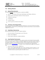
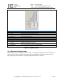
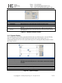
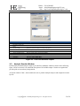
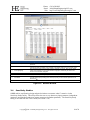
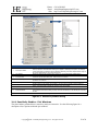
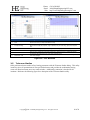
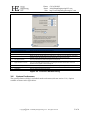
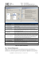
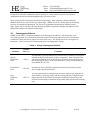
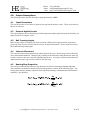
ORBIS
Modern Rolling-Element Bearing Analysis Software
USER’S MANUAL
(Updated for Version 2.2)
Copyright
2009 - 2012 Halpin Engineering, LLC. All rights reserved.
Table of Contents
1.0 Getting Started ................................................................................................................................. 4
1.1 System Requirements ..................................................................................................................... 4
1.2 End User License Agreement ......................................................................................................... 4
1.3 Installation Instructions .................................................................................................................. 4
1.4 Java Runtime Environment ............................................................................................................ 4
2.0 User Interface ................................................................................................................................... 5
2.1 Main Graphical Interface ................................................................................................................ 5
2.1.1
System Inputs .......................................................................................................................... 5
2.1.2
Dynamic Analysis Inputs ........................................................................................................ 6
2.1.3
System Display........................................................................................................................ 7
2.1.4
Bearing Row Inputs................................................................................................................. 8
2.1.5
Input Field Description ........................................................................................................... 8
2.1.6
User Menus ............................................................................................................................. 9
2.2 Database Editors ........................................................................................................................... 10
2.2.1
Bearing Database Editor........................................................................................................ 10
2.2.2
Material Database Editor ....................................................................................................... 12
2.2.3
Lubricant Database Editor ..................................................................................................... 12
2.3 Analysis Results Window............................................................................................................. 13
2.4 Sensitivity Studies ........................................................................................................................ 14
2.4.1
Sensitivity Studies - Plot Windows ....................................................................................... 15
2.5 Tolerance Studies ......................................................................................................................... 16
2.6 System Preferences ....................................................................................................................... 17
3.0 Technical Background ................................................................................................................... 18
3.1 Convergence Criteria .................................................................................................................... 19
4.0 Output Descriptions ....................................................................................................................... 20
4.1 Input Parameters ........................................................................................................................... 20
4.2 External Applied Loads ................................................................................................................ 20
4.3 Ball Crossing Angles .................................................................................................................... 20
4.4 Internal Clearances ....................................................................................................................... 20
4.5 Bearing Ring Properties ............................................................................................................... 20
4.6 Preload Data ................................................................................................................................. 21
4.7 Reaction Forces on Shaft .............................................................................................................. 21
4.8 Inner Ring Displacements ............................................................................................................ 21
4.9 Stiffness Output ............................................................................................................................ 21
4.9.1
Axial Stiffness ....................................................................................................................... 21
4.9.2
System Jacobian .................................................................................................................... 22
4.9.3
Row Stiffness Matrix ............................................................................................................ 22
4.10
Fatigue Life ............................................................................................................................... 22
4.11
Bearing Torque ......................................................................................................................... 22
4.12
Row Outputs (Element-Wise results) ....................................................................................... 22
4.12.1 Element Number ................................................................................................................... 22
4.12.2 Normal Ball Load .................................................................................................................. 23
4.12.3 Contact Angle........................................................................................................................ 23
4.12.4 Mean Hertz Stress ................................................................................................................. 23
4.12.5 Truncated Length .................................................................................................................. 23
4.12.6 Ellipse Semi Major ................................................................................................................ 23
4.12.7 Ellipse Semi Minor ............................................................................................................... 23
4.12.8 Max Sub-Surf Shear .............................................................................................................. 23
4.12.9 Max Shear Depth................................................................................................................... 23
Copyright
2009 - 2012 Halpin Engineering, LLC. All rights reserved.
4.12.10
Upper Edge Location ......................................................................................................... 23
4.12.11
Lower Edge Location ........................................................................................................ 23
4.12.12
Contact Normal Approach ................................................................................................. 24
4.12.13
Contact Normal Stiffness................................................................................................... 24
4.12.14
Spinning Velocity .............................................................................................................. 24
4.12.15
Rolling Velocity ................................................................................................................ 24
4.12.16
Spinning Torque ................................................................................................................ 24
4.12.17
Rolling Torque................................................................................................................... 24
4.12.18
Element Roll Velocity ....................................................................................................... 24
4.12.19
Pitch Orbit Velocity ........................................................................................................... 24
4.12.20
Minimum Film Height ....................................................................................................... 24
4.12.21
Minimum Lambda Value................................................................................................... 24
4.12.22
Centrifugal Force ............................................................................................................... 25
4.12.23
Gyroscopic Moment .......................................................................................................... 25
5.0 References ....................................................................................................................................... 26
Table of Figures
Figure 1. Main Graphical Interface .............................................................................................................. 5
Figure 2. System Inputs ............................................................................................................................... 6
Figure 3. Dynamic Analysis Inputs.............................................................................................................. 7
Figure 4. System Display ............................................................................................................................. 7
Figure 5. Bearing Row Inputs ...................................................................................................................... 8
Figure 7. User Menu's .................................................................................................................................. 9
Figure 6. Input Field Description ................................................................................................................. 9
Figure 8. Database Editors ......................................................................................................................... 10
Figure 9. Bearing Database Inputs ............................................................................................................. 11
Figure 10. Material Database Inputs .......................................................................................................... 12
Figure 11. Lubricant Database Inputs ........................................................................................................ 13
Figure 12. Results Window........................................................................................................................ 14
Figure 13. Sensitivity Studies Dialog ........................................................................................................ 15
Figure 14. Plot Windows ........................................................................................................................... 16
Figure 15. Tolerance Studies Dialog.......................................................................................................... 17
Figure 16. System Preferences ................................................................................................................... 18
Figure 17. Bearing Nomenclature .............................................................................................................. 21
Table of Tables
Table 1. Solver Convergence Criteria ........................................................................................................ 19
Copyright
2009 - 2012 Halpin Engineering, LLC. All rights reserved.
Phone: (310) 650-8982
Email: [email protected]
Web: http://www.HalpinEngineeringLLC.com
1.0
Getting Started
1.1 System Requirements
The following minimum system requirements are needed to run ORBIS.
Windows 7/Vista/Windows XP/Windows 2000/Windows 2003/Windows 2008 Server
Display monitor with minimum resolution of 1024 by 768 pixels
128 MB of free disk space
256 MB RAM
Available USB port
Java 6.0 or greater (see below for more details)
1.2
End User License Agreement
You must accept the terms and conditions specified in the End User License Agreement before installing
and using ORBIS. The agreement is provided during the installation routine and is also located within the
ORBIS folder on the CD.
1.3 Installation Instructions
Run the automated installer steps below to complete installation.
1. Insert the installation CD and navigate to your CD directory.
2. Double click the Setup.exe
3. Follow installer instructions to complete installation.
1.4 Java Runtime Environment
In order for the software to run properly, the host computer must have Java Runtime Environment (JRE)
version 6.0 or greater installed. The JRE is an industry standard and will generally already be installed on
most modern computers. If your computer does not have JRE 6.0 or greater already installed you may
install the version included from the installation directory or download the latest version from the
Sun/Oracle website (www.oracle.com). To install the version included from the ORBIS CD follow these
steps.
1. Open the Java folder on the CD (\\ORBIS\Java\)
2. Double click jre-6uXX-windows-i586-s.exe to install on Windows platforms (Windows 7, Vista,
Windows XP, Windows 2000, Windows 2003, and Windows 2008 Server). Note: the „XX‟ in
the filename denotes the particular update to the JRE Version 6.
Copyright
2009 - 2012 Halpin Engineering, LLC. All rights reserved.
4 of 26
Phone: (310) 650-8982
Email: [email protected]
Web: http://www.HalpinEngineeringLLC.com
2.0
User Interface
2.1 Main Graphical Interface
The main graphical interface allows the user to define their bearing system and perform analysis runs.
See subsequent sections (2.1.X) for detailed information about each input within the main graphical
interface. Once all necessary inputs have been entered the user selects the Analyze button to perform
their analysis. A new window will appear containing the analysis results. See section 2.3 for a
description on the Results window and section 4.0 for a detailed description on each output parameter.
System
Display
(2.1.3)
System
Inputs
(2.1.1)
Bearing Row
Inputs
(2.1.4)
Dynamic
Analysis
Inputs
(2.1.2)
Input Field
Description
(2.1.5)
Figure 1. Main Graphical Interface
2.1.1 System Inputs
The System Inputs area is where external loading and system material definitions are defined. See the
following figure for detailed descriptions of each input field.
Copyright
2009 - 2012 Halpin Engineering, LLC. All rights reserved.
5 of 26
Phone: (310) 650-8982
Email: [email protected]
Web: http://www.HalpinEngineeringLLC.com
1
2
3
4
5
6
7
8
9
10
11
12
#
Title
Description
1
Fx (lbf)
External axial load component (positive is toward the right)
2
Fy (lbf)
External radial load component (positive is upwards)
3
Fz (lbf)
External radial load component (positive is out of the page)
4
Fyy (in-lbf)
External moment about the Y-Axis
5
Fzz (in-lbf)
External moment about the Z-Axis
6
Load Location (in)
Location of external load point (along X-Axis)
7
Shaft Temperature (F)
Bulk temperature of the shaft
8
Housing Temperature (F)
Bulk temperature of the housing
10
Allowable Mean Hertzian
Stress (psi)
Shaft Material
Allows user to specify an allowable contact stress. All elements with contact stress above the specified
allowable will be highlighted in the output file.
Allows user to assign shaft material from the material database
11
12
Housing Material
Lubricant
Allows user to assign housing material from the material database
Allows user to assign lubricant to all bearing rows from the lubricant database
9
Figure 2. System Inputs
2.1.2 Dynamic Analysis Inputs
ORBIS offers both static and dynamic analysis modes. See the following figure for detailed descriptions
of the available options. Dynamic analysis mode provides additional user output parameters (such as
torque, fatigue life, film parameters, centrifugal and gyroscopic forces, etcetera).
Copyright
2009 - 2012 Halpin Engineering, LLC. All rights reserved.
6 of 26
Phone: (310) 650-8982
Email: [email protected]
Web: http://www.HalpinEngineeringLLC.com
1
2
3
4
5
6
#
Title
Description
1
Dynamic Analysis Checkbox
Selection of this checkbox activates the dynamic analysis inputs. Default is un-checked.
2
Rotational Member
Radio buttons allow user to specify either ‘shaft rotates’ or ‘housing rotates.’
3
Loaded Member
Radio buttons allow user to specify whether load is fixed relative to the shaft or housing.
4
Velocity (rmp)
Defines the rotational velocity, in RPM, of the rotational member
5
Reliability
6
Life Factor
Defines the reliability for fatigue life. Valid inputs are between 0 and 1, exclusive. Default is 0.9 (L10
equivalent).
Allows user to specify an overall combined life adjustment factor. ORBIS will compute reliability and
lubricant regime adjustment factors, however other factors such as material and operating environment
must included here.
Figure 3. Dynamic Analysis Inputs
2.1.3 System Display
The system display area provides a proportional sketch of the user defined system. See the following
figure for a detailed description of the information provided in the system display panel. It is
recommended that the user review the system sketch just prior to selecting the analyze button to ensure
their setup is correct.
1
6
2
4
7
8
3
#
5
9
Title
Description
1
Sketch – Bearing Name
Displays the name of each bearing row defined in the system.
2
Sketch – Bearing Orientation
Bearing is shown with defined contact angle.
3
Sketch – Row location
4
Sketch – Coordinate System
Axial location (x-axis) of each bearing row is shown. Left-most bearing or load point will be normalized to
zero position.
Coordinate system shown at relative load point.
5
Sketch – Load location
Axial location (along x-axis) of load application point shown.
6
Button – Sketch
Button refreshes the sketch window with current user-defined inputs.
7
Button – Bearings
Button opens the Bearing Database dialog window.
8
Button – Materials
Button opens the Material Database dialog window.
9
Button - Lubricants
Button opens the Lubricant Database dialog window.
Figure 4. System Display
Copyright
2009 - 2012 Halpin Engineering, LLC. All rights reserved.
7 of 26
Phone: (310) 650-8982
Email: [email protected]
Web: http://www.HalpinEngineeringLLC.com
2.1.4 Bearing Row Inputs
The Bearing Row Input area is where the user defines necessary inputs for each bearing row in the
system. See the following figure for a detailed description of each input type.
1
2
3
5
9
10
11
4
12
13
#
Title
6
14
7
15
8
16
Description
Drop-down selection allows up to 5 bearing rows to be specified. Row tabs (see #2) will be activated
based on number of bearing rows selected here.
Row tabs are activated based on the number of bearing rows selected. Selecting an active tab allows the
user to define parameters for that row.
Contact angle definition for active row. A divergent contact angle extends away from, or diverges, from
the spin axis as you traverse in the positive direction along the x-axis.
Specification for type of preloading. Options are rigid or spring. Rigid preloading activates input fields for
inner and outer ring clamping forces. Spring preloading activates inputs for the spring rate.
Specifies the condition at which the specified preload is defined. Un-mounted conditions means the rings
are radially free at the specified preload. Mounted conditions apply the preload force based on the
mounted fit-up conditions, which include changes to internal clearance from interference fitting and ring
clamping.
1
# Bearing Rows
2
Row Tabs
3
Contact Angle
4
Preload Type
5
Preload Condition
6
I.R. Clamp Load (lbf)
Input field for the inner ring clamp load. Only active for rigid preload type.
7
O.R. Clamp Load (lbf)
Input field for the outer ring clamp load. Only active for rigid preload type.
8
Spring Rate (lbf/in)
Input field for the preload spring stiffness. Only active for spring preload type.
9
Bearing
Drop-down selection to assign the bearing for the active row. The drop-down menu will contain all
bearings defined in the user defined bearing database.
10
Row Location (in)
Input field for the axial location (along x-axis) of the active bearing row.
11
I.R. Fitup (in)
12
O.R. Fitup (in)
13
Shaft I.D. (in)
14
Housing O.D. (in)
15
Row Preload (lbf)
16
Coeff of Friction, Ball Contact
Input field for the inner ring fitup to the shaft. Fitup is defined as the difference in the shaft O.D. to the
free bearing I.D. A positive value indicates interference fits.
Input field for the outer ring fitup to the housing. Fitup is defined as the difference in the free bearing
O.D. and the housing I.D. A positive value indicates interference fits.
Specifies the I.D. of a hollow shaft. For non-constant shaft wall thicknesses use the appropriate shaft I.D.
at the bearing row location. For a solid shaft input a zero value.
Specifies the O.D. of the housing. For non-constant housing wall thicknesses use the appropriate housing
O.D. at the bearing row location.
Specifies the preload force applied to the active bearing row. Preload forces are directional and must
include the appropriate sign convention. To preload a bearing through its contact angle, standard
preloading, specify a positive preload for divergent contact angles and a negative preload for convergent
contact angles.
Specifies the rolling contact friction coefficient for the active bearing row.
Figure 5. Bearing Row Inputs
2.1.5 Input Field Description
The input field description area provides helpful information to the user for all input fields. When the
user places their cursor in one of the input fields (done by clicking the mouse in a field or pressing the tab
Copyright
2009 - 2012 Halpin Engineering, LLC. All rights reserved.
8 of 26
Phone: (310) 650-8982
Email: [email protected]
Web: http://www.HalpinEngineeringLLC.com
button to advance to the next input field) a description about that field appears in the Input Field
description area. The following figure illustrates this.
Cursor placed in field
Figure 6. Input Field Description
2.1.6 User Menus
User menus are available within the main graphical interface. See the following figure for a detailed
description of the available menu options.
1
2
3
4
5
6
#
Title
Description
1
File Menu
The file menu provides standard file options such as Open, Save, Save As and Exit. ORBIS maintains its
own file type that allows the user to save their bearing analysis setup. All parameters within the main
graphical interface are preserved.
2
Tools Menu
The tools menu provides advanced analysis utilities.
3
Batch Process Load Cases
4
Sensitivity Studies
5
Tolerance Studies
6
System Preferences
Selecting this utility allows the user to load a pre-configured comma delimited file with an unlimited number
of load cases. Each load case is applied to the current defined bearing system and the results are saved to
separate results files.
Selecting this utility launches the Sensitivity Studies window. See section 2.4 for a detailed explanation of
the powerful capabilities of this utility.
Selecting this utility launches the Tolerance Analysis window. See section 2.5 for a detailed explanation of
the powerful capabilities of this utility.
Selecting this utility launches the System Preferences window. See section 2.6 for a detailed explanation of
the powerful capabilities of this utility.
Figure 7. User Menu's
Copyright
2009 - 2012 Halpin Engineering, LLC. All rights reserved.
9 of 26
Phone: (310) 650-8982
Email: [email protected]
Web: http://www.HalpinEngineeringLLC.com
2.2 Database Editors
Database editors allow the user to view, modify, add and delete bearing, material, and lubricant database
entries. The database editors are accessed from the buttons within the System Display area (see section
2.1.3).
Orbis uses bearing, material and lubricant databases to define the majority of input parameters required to
perform a bearing analysis. Once the user has defined their database entries they simply assign them to
their analysis via drop-down menus.
Figure 8. Database Editors
2.2.1 Bearing Database Editor
The Bearing Database Editor allows you to view, edit, add or delete bearing definitions to the bearing
database. See the following figure for a detailed description of the editor.
Copyright
2009 - 2012 Halpin Engineering, LLC. All rights reserved.
10 of 26
Phone: (310) 650-8982
Email: [email protected]
Web: http://www.HalpinEngineeringLLC.com
1
2
8
14
3
9
15
4
10
16
5
11
17
6
12
18
13
19
7
20
21
23
22
24
25
26
#
Title
Description
1
Bearing Name
Specify a name for the bearing.
2
Pitch Diameter (in)
Diameter that describes the rolling element centers (often the average between the bearing I.D. and O.D.)
3
Free Contact Angle (deg)
Contact angle of bearing with no external loading. Must be a positive value.
4
Element Diameter (in)
Diameter of the ball.
5
Number of Elements
Number of balls in a single bearing row.
6
RMS Roughness (Microinch)
Surface roughness, RMS, of the ball.
7
Material
Assign materials from Material Database to the rolling elements, inner ring and outer ring.
8
Inner Diameter (in)
Bearing’s inner diameter.
9
I.R. Width (in)
Width along the bearing axis of the inner ring.
10
Raceway Curvature
Inner ring curvature, expressed as the ratio of the raceway radius to the ball diameter.
11
Land Height (h/d)
12
Dam Height (h/d)
13
RMS Roughness (Microinch)
Surface roughness, RMS, of the inner raceway.
14
Outer Diameter (in)
Bearing’s outer diameter.
15
O.R. Width (in)
Width along the bearing axis of the outer ring.
16
Raceway Curvature
Inner ring curvature, expressed as the ratio of the raceway radius to the ball diameter.
17
Land Height (h/d)
18
Dam Height (h/d)
19
RMS Roughness (Microinch)
Surface roughness, RMS, of the outer raceway.
20
Edit Materials Button
Opens the Material Database Editor.
21
Clear All Entries Button
Clears all current input field entries. This does NOT clear the database entries.
22
Add To Database Button
23
Database Entry
24
View/Edit Properties Button
25
Delete Entry Button
With a database entry selected, this button will permanently delete the entry from the database.
26
Close Button
Closes the Bearing Database Editor.
Height of the land diameter expressed as the ratio of the radial height to the ball diameter. The land is
specified as the shoulder that contains the loaded contact zone.
Height of the dam diameter expressed as the ratio fo the radial height to the ball diameter. The dam is
specified as the shoulder the is unloaded, or opposite the contact angle.
Commits the specified input entries into the database under the bearing name specified. A warning will
occur if the specified bearing name already exists within the database.
This window provides all current bearing names within the database. This window will fill up with multiple
columns of data as eventually become a scrollable window to provide all database entries.
Once a database entry is selected within the database window, selecting this button will populate the
bearing parameters into the input fields.
Figure 9. Bearing Database Inputs
Copyright
2009 - 2012 Halpin Engineering, LLC. All rights reserved.
11 of 26
Phone: (310) 650-8982
Email: [email protected]
Web: http://www.HalpinEngineeringLLC.com
2.2.2 Material Database Editor
The material database editor allows the user to define their own unique materials. See the following
figure for a detailed description of the material editor.
1
2
3
4
5
6
7
8
9
10
11
#
Title
Description
1
Material Name
Specify a name for the material.
2
Young’s Modulus (psi)
Specifies Young’s Modulus for the material.
3
Poisson’s Ratio
Specifies Poisson’s ratio for the material.
4
Specific Density (lbm/in3)
Specifies the specific density of the material.
6
Coefficient of Thermal
Expansion (in/in-°F)
Clear Entries Button
7
Add To Database Button
Adds new entire to the Material Database.
8
Material Database Window
Shows the current entries in the Material Database.
9
View Parameters Button
Displays the parameters of a selected material database entry.
10
Delete From Database Button
Deletes the selected database entry from the database.
11
Close Button
Closes the Bearing Database Editor.
5
Specifies the coefficient of thermal expansion for the material.
Clears all input entries (does NOT clear the database entries).
Figure 10. Material Database Inputs
2.2.3 Lubricant Database Editor
The lubricant database editor allows the user to define their own unique lubricants. See the following
figure for a detailed description of the lubricant editor.
Copyright
2009 - 2012 Halpin Engineering, LLC. All rights reserved.
12 of 26
Phone: (310) 650-8982
Email: [email protected]
Web: http://www.HalpinEngineeringLLC.com
1
2
3
4
5
6
7
8
9
#
1
2
3
Title
Description
Lubricant Name
Specify a name for the lubricant.
Atmospheric Viscosity (lbfsec/in2)
Pressure Coefficient of
Viscosity (in2/lbf)
Specifies the viscosity of the lubricant.
Specifies the pressure coefficient of viscosity of the lubricant.
4
Clear Entries Button
Clears all input entries (does NOT clear the database entries).
5
Add To Database Button
Adds new entry to the Lubricant Database.
6
Lubricant Database Window
Shows the current entries in the Lubricant Database.
7
View Parameters Button
Displays the parameters of a selected lubricant database entry.
8
Delete From Database Button
Deletes the selected database entry from the database.
9
Close Button
Closes the Lubricant Database Editor.
Figure 11. Lubricant Database Inputs
2.3 Analysis Results Window
Professionally formatted analysis output is provided in a standalone window as shown in the following
figure. Refer to section 4.0 for a detailed description of all available output. Results are organized to
provide quick access and easy interpretation.
All results windows „float‟, which enables the user to perform multiple analyses and compare them sideby-side.
Copyright
2009 - 2012 Halpin Engineering, LLC. All rights reserved.
13 of 26
Phone: (310) 650-8982
Email: [email protected]
Web: http://www.HalpinEngineeringLLC.com
1
2
3
4
5
#
Title
6
7
Description
Key result parameters are tabulated for each bearing row. This area provides quick access to available key
parameters.
A scrollable/selectable text window containing the complete analysis output. See section 4.0 for a
comprehensive listing of available output contained in the detailed results section of the results window.
Result highlighting makes important result parameters impossible to overlook. Each element Hertzian
contact stress exceeding the user specified allowable is highlighted. Additionally, all elements with
truncation are automatically highlighted.
1
Result Summary
2
Detailed Results
3
Result Highlighting
4
Adjust Font Size
Font slider adjusts font size, in 1pt increments, for all the detailed results text.
5
Print Button
Brings up a standard print dialog. Only the detailed results are printed.
6
Save Button
Save copies the contents of the results window to a delimited text file. The delimited text file provides the
user with unlimited post processing options and easy importing to various software platforms such as
Microsoft Excel .
7
Close Button
Closes the results window.
Figure 12. Results Window
2.4 Sensitivity Studies
ORBIS enables rapid bearing design and quick solutions to common „what if‟ scenarios via the
Sensitivity Studies utility. This utility allows the user to vary almost any input parameter (independent
parameter) and plot them against any output parameter (dependent parameter). The Sensitivity Study
dialog is accessed from the „Tools‟ menu (see section 2.1.6).
Copyright
2009 - 2012 Halpin Engineering, LLC. All rights reserved.
14 of 26
Phone: (310) 650-8982
Email: [email protected]
Web: http://www.HalpinEngineeringLLC.com
1
2
3
4
5
6
7
8
#
9
Title
Description
1
Select Input Variable
Drop-down menu to select independent variable (see parameter options in the figure to the right). Note:
each input parameter associated with a bearing row is applied to all bearings in the system. For example,
if ‘Free Contact Angle’ is selected as the input parameter all bearing rows will be analyzed with the range of
free contact angles defined in entry fields 2 and 3 below.
2
Vary From/To
Specifies the minimum and maximum values, inclusive, to vary the independent variable between.
3
# of Increments
4
Nominal Value, Row 1
5
Select Output Row
Specifies which output row to be used to plot output (dependent variable).
6
Output Variable Selections
Checkbox selection of all possible output variables. User may select any number of output variables to
analyze. Orbis will provide a separate plot window for each output variable.
7
Export raw data to file
Selecting this checkbox will allow the user to save the raw plot data to a delimited text file.
8
Plot Results Button
Button to perform analysis and plot final results. If user selected ‘Export raw data to file’ checkbox the user
will be presented with ‘File Save’ dialog to specify a file name and directory for the data file prior to plotting
the data.
9
Close Button
Closes the Sensitivity Studies dialog.
Specifies the number of points to plot. Orbis will use the specified variable limits and number of increments
to determine equally spaced data points. Default value is 5 increments.
This is a non-editable field that provides the nominal value of the selected independent parameter. This is
provided for user reference.
Figure 13. Sensitivity Studies Dialog
2.4.1 Sensitivity Studies - Plot Windows
The plot windows generated from a sensitivity study are interactive. See the following figure for a
description of user options within the plot windows.
Copyright
2009 - 2012 Halpin Engineering, LLC. All rights reserved.
15 of 26
Phone: (310) 650-8982
Email: [email protected]
Web: http://www.HalpinEngineeringLLC.com
5
1
4
2
6
3
#
Title
Description
Data is plotted with a ‘smooth’ curve fit where actual solution points are indicated with circles. Note: the
smooth curve fit may not always follow data accurately.
The plot options dialog appears by selecting the right mouse button anywhere within the plot window.
Options exist to modify plot properties, copy to clipboard, save plot as an image, print, and zoom/scale
axes.
1
Curve
2
Plot Options Dialog
3
Independent Parameter
All plots have the independent parameter along the abscissa. Appropriate units will be specified.
4
Dependent Parameter
All plots have the dependent parameter along the ordinate. Appropriate units will be specified.
5
Mouse Zoom - Start
6
Mouse Zoom - End
Mouse zooming (rectangular) is achieved by selecting the upper left corner of a rectangle with the left
mouse button and dragging the mouse to the lower right hand corner.
To complete zoom release the left mouse button with the mouse pointer at the desired lower right corner
of the zoom rectangle.
Figure 14. Plot Windows
2.5 Tolerance Studies
Orbis performs tolerance studies of key bearing parameters with the Tolerance Studies dialog. This utility
iteratively solves all permutations of user specified tolerances and provides the combination causing
worst case Hertzian contact stress in a results window. Additionally, truncation is checked for all
iterations. Reference the following figure for a description of the Tolerance Studies utility.
Copyright
2009 - 2012 Halpin Engineering, LLC. All rights reserved.
16 of 26
Phone: (310) 650-8982
Email: [email protected]
Web: http://www.HalpinEngineeringLLC.com
1
2
3
4
5
6
7
8
#
9
Title
Description
1
Free Contact Angle (deg)
Specify min and max free contact angles in degrees.
2
Inner Raceway Curvature
Specify min and max inner raceway curvatures (ratio of raceway radius to ball diameter).
3
Outer Raceway Curvature
Specify min and max outer raceway curvatures (ratio of raceway radius to ball diameter).
4
Preload
5
Vary Sign Convention
6
Apply Tolerances to all rows
7
Row Selection Drop-down
When active the drop-down menu is used to specify which bearing row to apply the specified tolerances to.
8
Analyze Button
Button to begin analysis of tolerances.
9
Close Button
Closes the Tolerance Analysis dialog window.
Specify min and max preload (always as a positive value). Orbis will correct sign based on contact angle
orientation and the assumption that the preload should load through the contact angle.
Checkbox to specify if sign convention should be varied on all load components. Selecting this checkbox
will run all permutations of positive and negative load components.
Checkbox to specify how tolerances are applied to the system. Selecting this checkbox causes all bearing
rows to have specified tolerances analyzed. Un-selecting this checkbox activates item 7 below and
tolerances are only applied to selected bearing row.
Figure 15. Tolerance Studies Dialog
2.6
System Preferences
The system preferences dialog is available from the tools menu (reference section 2.1.6). Options
available are shown in the figure below.
Copyright
2009 - 2012 Halpin Engineering, LLC. All rights reserved.
17 of 26
Phone: (310) 650-8982
Email: [email protected]
Web: http://www.HalpinEngineeringLLC.com
1
2
8
9
5
7
3
10
6
11
12
4
13
14
#
Title
Description
1
Tabbed Pane Selection
Each system preference category is accessed by selecting the appropriate tab.
2
Database Location
3
Select Database Type
4
Load Remote Database
5
Remote Database Entries
6
Import button
7
Default Database Entries
Displays the entries from the user’s default database.
8
System Force Balance Error
This entry specifies the allowable system force balance error for solver convergence (Norm of the
residuals). Acceptable values are between zero and one exclusive [0<value<1]. The system force balance
convergence criteria will be determined by multiplying this value by the RSS of the applied external loading.
In the case where the RSS of the external loading is less than one this value will be used directly. For
example, if the RSS of the external loading is 1,000 lbf and the system force balance error is 1.0E-5
(default value), then the system will converge to equilibrium within 0.01 lbf.
9
Max Solver Iterations
Specifies the maximum number of numerical solver iterations before aborting.
10
Max Preload Error
This entry specifies the maximum allowable force error for determining the preloaded state. Acceptable
values are greater than zero [0<value].
11
Max Preload Iterations
Specifies the maximum number of numerical solver iterations on preload convergence before aborting.
12
Max Internal Clearance Error
Specifies the maximum allowable internal clearance error for convergence, in inches. Acceptable values are
greater than zero [0<value]. During mounting and preloading routines the solver will converge on each
bearing row’s change in internal clearance within this value.
13
Reset Defaults
Select this button to restore all solver options to their default values.
14
Close Button
Closes the system preference dialog window.
This area contains the folder location to the default database files. The browse button brings up a folder
selection dialog that allows the user to specify their preferred directory for storing their databases.
To perform a database import, or simply view contents of a database, the user must select which type of
database to be displayed. Once the type is specified the two scroll panes (see #6 & #7) populate with the
appropriate entry names.
Select this button to bring up a folder selection dialog. Within the folder selection dialog the user will
navigate to a desired database. Note: this button is only active once a database type is specified.
Displays entries from remote database. Single entry selection is achieved by mouse selection (left click) on
desired entry. Multiple entry selection is achieved by two methods: for consecutive entry selection select
the first desired entry and shift+click the last consecutive entry, for non-consecutive entry selection select
each entry while holding the control key.
Selecting this button imports the selected remote database entries into the default database. The database
does not allow duplicate entries and will check each import entry for existing names within the default
database. If duplicates are found the user will be asked to confirm overwriting or skip the duplicate import.
Figure 16. System Preferences
3.0
Technical Background
ORBIS uses numerical techniques to solve the user defined system of one or more bearing rows
simultaneously. A solution to the system is achieved when the sum of all bearing row reaction forces is
sufficiently close to the external applied forces (system equilibrium). ORBIS does not use pre-generated
Copyright
2009 - 2012 Halpin Engineering, LLC. All rights reserved.
18 of 26
Phone: (310) 650-8982
Email: [email protected]
Web: http://www.HalpinEngineeringLLC.com
lookup tables within the computations and all solutions are, unless otherwise specified, based on the
mathematical theories developed and published by A.B. Jones (1964).
Some outputs provide results based on mounted contact angle. When a bearing is defined within the
database editor the user specifies the free contact angle. ORBIS uses the free contact angle as the starting
point for all subsequent computations. The first set of computations determines the mounted contact
angle. Inputs such as I.R. and O.R. Fitup, Housing and Shaft Temperatures changes from ambient (68°F),
and preloads influence the mounted contact angle.
3.1 Convergence Criteria
ORBIS uses the IEEE 754 technical standards for all floating point arithmetic. All calculations use at
least 64-bit precision. Key calculations pertaining to matrix inversion and the overall system Jacobian are
extended to 128-bit precision to improve accuracy of the solver. The default criteria for convergence are
show below. Refer to section 2.6 for instructions on how to change these settings.
Table 1. Solver Convergence Criteria
Parameter
System
Equilibrium
Error
Preload Force
Error
Ring
Expansion
Error
Default
Error (±)
0.001%
Comments
The allowable system equilibrium error is defined as a percentage of the applied
external loading (Euclidean norm of force components). Error is defined as the
difference between the norm of all bearing row reaction forces and the norm of
the external applied forces. In the case where there is zero external loading the
error defaults to 1.0E-5 lbf.
1.0E-5 lbf.
Preload force error is defined as the difference between the bearing reaction
forces and the applied preload force.
1.0E-7 in.
The ring expansion error is defined as the difference between ΔPD input into the
Jones model (a „fixed ring‟ model) and the resulting ΔPD due to ring deflections.
Ring deflections are determined by using the resulting ball normal forces and
associated contact angle to determine an equivalent radial pressure on the bearing
ring.
Copyright
2009 - 2012 Halpin Engineering, LLC. All rights reserved.
19 of 26
Phone: (310) 650-8982
Email: [email protected]
Web: http://www.HalpinEngineeringLLC.com
4.0
Output Descriptions
The following sections describe the analysis output generated by ORBIS.
4.1 Input Parameters
This section provides a list of the user inputs used to generate the analysis results. These are provided to
the user as reference.
4.2 External Applied Loads
This section displays the user defined system load components and the application point at which they are
applied (location is along the x-axis).
4.3 Ball Crossing Angles
Ball Crossing Angles are displayed for each row and are defined as the angular rotation required by a
given ring, inner or outer, to cause a ball to travel to an adjacent ball station. These results are based on
the mounted bearing contact angle.
4.4 Internal Clearances
This section provides bearing diametral (or radial) and axial free-play. Results are given for both initial
(free) and mounted conditions. Diametral play is defined as the total linear radial distance the inner ring
can move relative to the outer ring with negligible applied force. Axial play is defined as the total axial
displacement the inner ring can move relative to the outer ring.
4.5 Bearing Ring Properties
This section provides the equivalent raceway diameters used for the mounting/preloading algorithm.
These diameters are defined as function of the bearing geometry as shown in the following figure. The
bearing inner and outer diameter expansion from fitup and preloading, at both unmounted and mounted
condition, is also included.
Copyright
2009 - 2012 Halpin Engineering, LLC. All rights reserved.
20 of 26
Phone: (310) 650-8982
Email: [email protected]
Web: http://www.HalpinEngineeringLLC.com
Figure 17. Bearing Nomenclature
4.6 Preload Data
This section provides the applied preload, resulting mounted preload and corresponding axial deflections
for each bearing row. The axial deflection shown is purely due to the mounted preload condition.
4.7 Reaction Forces on Shaft
This section provides the resulting bearing reaction force components on the shaft at each bearing row.
These forces include all mounting, preloading and external loading conditions and apply at the center of
their respective bearing row locations.
4.8 Inner Ring Displacements
This section provides the components of the displaced inner rings due to mounting, preloading and
external loading. All non-axial results are based on fixed outer ring theory developed by Jones (1964).
4.9 Stiffness Output
Orbis provides three different types of stiffness calculations: axial stiffness with ring compliance
considerations, system Jacobian diagonal terms, and complete 5x5 stiffness derivatives for each bearing
row. Refer to subsequent sections for a description of each type of stiffness result.
4.9.1 Axial Stiffness
This result provides the system axial stiffness, at mounted and preloaded state, with compliant ring
considerations. Effects from external loading are not included in this result.
Copyright
2009 - 2012 Halpin Engineering, LLC. All rights reserved.
21 of 26
Phone: (310) 650-8982
Email: [email protected]
Web: http://www.HalpinEngineeringLLC.com
4.9.2 System Jacobian
This result provides the system Jacobian diagonal terms. These result apply in the fully loaded condition.
Additionally, the system Jacobian assumes a rigid system during external load application. The system
Jacobian results apply at the center point of the user‟s system (e.g. if the user system contained two rows
placed at -0.5” and +0.5” along the x-axis the system Jacobian would be computed at x=0.0”).
4.9.3 Row Stiffness Matrix
This section provides complete 5x5 stiffness derivatives for each bearing row. Stiffness results
correspond to the quasi-static equilibrium state of the system in its final loaded state.
4.10 Fatigue Life
This section provides individual ring and total system fatigue cycles for various conditions. Note: Fatigue
results are only generated for dynamic analysis runs. Outputs include L10 life, adjusted L10 life, and
adjusted life with consideration for film thickness. L10 Fatigue life calculations are based on the
Lundberg – Palmgren theories as shown in Jones (1964). The adjusted life output is based on the life
factor theory adopted in AFBMA (1990) standards. This result includes the user defined life factor input
along with a computed factor based on the user reliability input.
The life factor input allows the user to enter a combined factor to account for items such as materials,
cleanliness, and misalignments. Bamberger (1971) provides a useful reference for computing various life
factors. The adjusted life with film includes an additional lubricant factor, which is also provided for
reference. The film parameter is from Bamberger (1971) and follows the AFMBA recommended average
curve and uses the minimum film parameter as discussed below. All fatigue calculations use the
individual rolling element results and do not require determination of an equivalent radial load on the
bearing row.
4.11 Bearing Torque
Bearing torque results are only generated for dynamic analysis runs. The bearing torque output represents
the torque associated with rolling and spinning within the contact area. Precisely, this is the torque due to
interfacial slip (aka Heathcoate Slip) at the contact ellipse. It is important to note that there are numerous
other factors, such as lubricant shear/churning or cage drag, which can have a profound effect on bearing
torque. ORBIS uses the „Race Control‟ theory from Jones (1964) and therefore only allows spin to occur
on one raceway. The computed torque output can be scaled with the coefficient of friction input
parameter. Reference Jones (1964) for the torque calculations used by ORBIS.
4.12 Row Outputs (Element-Wise results)
Detailed outputs for each element of each row are provided in tabular form. Output tables are repeated
for each bearing row in the user‟s system. These tables differ depending on whether the analysis is static
or dynamic. All outputs correspond to the system equilibrium state after application of all external
loading.
4.12.1
Element Number
The Element Number is simply an indexing scheme to identify each of the rolling-elements uniquely.
Copyright
2009 - 2012 Halpin Engineering, LLC. All rights reserved.
22 of 26
Phone: (310) 650-8982
Email: [email protected]
Web: http://www.HalpinEngineeringLLC.com
4.12.2
Normal Ball Load
The Normal Ball Load is the load applied by each ball into each raceway contact. This load is directly
normal to the contact ellipse.
4.12.3
Contact Angle
The Contact Angle output describes the angle of the normal ball load vector.
4.12.4
Mean Hertz Stress
The Mean Hertz Stress output represents the average Hertzian contact stress over the elliptical contact
area. Peak stress for an elliptical contact can be computed by multiplying the mean stress by 3/2. ORBIS
will automatically highlight, in red, all values that exceed the user defined allowable mean Hertzian stress
from the main user interface. All stress results assume the contact ellipse if fully contained within the
raceway.
4.12.5
Truncated Length
The Truncated Length represents the percent of the total length of the contact ellipse, along the major
axis, that is truncated due to shoulder or dam override. ORBIS will automatically highlight all elements
that have any truncation.
4.12.6
Ellipse Semi Major
The Ellipse Semi Major output represents one half of the major dimension of the contact ellipse.
4.12.7
Ellipse Semi Minor
The Ellipse Semi Minor output represents one half of the minor dimension of the contact ellipse.
4.12.8
Max Sub-Surf Shear
The Max Sub-Surface Shear is the peak shear stress developed below the raceway surface due to contact
stress.
4.12.9
Max Shear Depth
The Max Shear Depth is the location along the normal to the contact area, below the raceway surface, at
which maximum shear stress is developed.
4.12.10
Upper Edge Location
The Upper Edge Location represents the edge of the contact ellipse that is closest to the land diameter.
This value is represented as a ratio of its height from the center of the raceway to the ball diameter.
4.12.11
Lower Edge Location
The Lower Edge Location represents the edge of the contact ellipse that is closest to the dam diameter.
This value is represented as a ratio of its height from the center of the raceway to the ball diameter.
Copyright
2009 - 2012 Halpin Engineering, LLC. All rights reserved.
23 of 26
Phone: (310) 650-8982
Email: [email protected]
Web: http://www.HalpinEngineeringLLC.com
4.12.12
Contact Normal Approach
Contact Normal Approach represents the total combined deflection of the contacting bodies (rollingelement and raceway). This deflection is along the normal direction to the contact area.
4.12.13
Contact Normal Stiffness
Contact Normal Stiffness represents the stiffness of the rolling-element to raceway contact area stiffness
in the normal direction.
4.12.14
Spinning Velocity
Spinning Velocity is the angular velocity of rolling-element spin relative to the un-controlling raceway.
Per Jones‟ (1964) race control theory, spin can only occur on one raceway while pure rolling occurs on
the other. Based on the spinning velocity output one can deduce race control (i.e. if there is zero spinning
velocity on a given raceway than that raceway is „in control‟).
4.12.15
Rolling Velocity
Rolling Velocity is the absolute angular velocity of the rolling element relative to the raceways.
4.12.16
Spinning Torque
Spinning Torque is the component of torque generated by interfacial slip within the contact area due to
rolling-element spin.
4.12.17
Rolling Torque
Rolling Torque is the component of torque generated by interfacial slip within the contact area due to
pure rolling.
4.12.18
Element Roll Velocity
The Element Roll Velocity represents the rotational velocity of the rolling elements as seen relative to the
pitch orbit velocity.
4.12.19
Pitch Orbit Velocity
The Pitch Orbit Velocity is the rotational velocity of the bearing pitch diameter about its spin axis. This
is essentially the angular velocity of rolling-element cage or retainer.
4.12.20
Minimum Film Height
The Minimum Film Height represents the thinnest point of the lubricant within the contact ellipse. This
calculation is based on the „Hard-EHL‟ theory by Hamrock and Dowson (1981) for fully flooded
conditions.
4.12.21
Minimum Lambda Value
Lambda is a dimensionless parameter that is often used to describe the lubricant regime of the bearing.
Its value is determined by taking the ratio of the minimum film height to the root sum squares (RSS) of
the contacting surface roughness. Mathematically, lambda is defined as follows.
Copyright
2009 - 2012 Halpin Engineering, LLC. All rights reserved.
24 of 26
Phone: (310) 650-8982
Email: [email protected]
Web: http://www.HalpinEngineeringLLC.com
4.12.22
Centrifugal Force
The Centrifugal Force output represents the radial body force of the rolling element due to its orbital
velocity and mass. This force tends to create differing contact angles between the inner and outer race
contacts and is treated in the analysis per Jones (1964).
4.12.23
Gyroscopic Moment
The Gyroscopic Moment output represents the spinning body moment of the rolling element due to its
angular velocity and inertia. The influences of this force are treated in the analysis per Jones (1964).
Copyright
2009 - 2012 Halpin Engineering, LLC. All rights reserved.
25 of 26
Phone: (310) 650-8982
Email: [email protected]
Web: http://www.HalpinEngineeringLLC.com
5.0
References
Anon.,(1990) “Load Ratings and Fatigue Life for Ball Bearings,” ANSI/AFBMA 9-1990, The AntiFriction Bearing Manufacturers Associations, Washington, DC.
Bamberger, E. N. (1971) Life Adjustment Factors for Ball and Roller Bearings – An Engineering Design
Guide, American Society for Mechanical Engineers, New York
Hamrock, B. J. and Dowson, D. (1981) Ball Bearing Lubrication – The Elastohydrodynamics of Elliptical
Contacts, Wiley, New York, N.Y.
Jones, A. B. (1964) “The Mathematical Theory of Rolling-Element Bearings,” in Mechanical Design and
Systems Handbook, H. A. Rothbart, ed., McGraw-Hill, New York, N.Y. article 13.
Copyright
2009 - 2012 Halpin Engineering, LLC. All rights reserved.
26 of 26