1
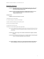
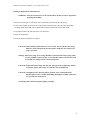
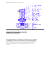
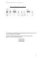
CIRCLE SEAL CONTROLS
ATKOMATIC SOLENOID VALVES
INSTALLATION, MAINTENANCE, AND OPERATION
INSTRUCTIONS
STAINLESS NORMALLY CLOSED SEMI-DIRECT LIFT VALVES
15800 SERIES
Installation Instructions
WARNING: These instructions should be read, understood, and followed before installation.
Failure to do this can extremely dangerous and cause valve malfunction.
1. An adequate filter system must be installed in the line ahead of each valve to prevent foreign matter from
damaging the seal faces and/or obstructing the valve orifices causing operational failure and leakage. A
maximum rating of such a filter is 40 microns to provide adequate protection.
2. Pipe thread sealing compounds and tape must be prevented from entering the valve.
3. New systems must be adequately flushed to remove all pipe scale, weld slag, thread burrs, etc. It is
typically necessary to flush new systems several times, removing contamination lodged in filters and
other components, until no debris is present.
4. Valves must be installed in a horizontal line with the coil oriented up (within +/- 10 degrees).
5. Mount the valve in the line such that the arrow cast into the valve body is in the direction of flow.
6. Check the nameplate and provide the specified voltage to the coil. Voltages must be as specified at the
coil rather than the power supply. This is particularly important with DC applications due to their
typically high voltage drop through supply lines. All AC coils are for single phase use only.
7 Coil housings may be rotated as required to match up with supply wiring. This is done by loosening the
housing nut at the top center of the coil housing, rotating the coil housing assembly, and re-tightening the
coil housing nut. Do not splice the lead wires inside the coil housing.
Note: On valves equipped with combination explosion proof and waterproof housings, the silicone
seal bead must be replaced after adjusting the housing to maintain the integrity of the water
proof housing.
Note: On valves equipped with explosion proof coil housings it is necessary to use shims to align
the coil housing. A set of these shims is included with each valve with an explosion proof
housing. The part number for this shim kit is 61427 (Atko p/n 229). If the angular alignment
of the coil housing is not important the installation of the shims is not required.
Atkomatic 15,800 Series Manual – Circle Seal Controls, Inc.
Instructions for Installing Shims
a. Unscrew the cast iron coil housing assembly from the valves bonnet or cylinder cap.
Note: If holding the valve in a vise, clamp on it either end to end or on the hex portion.
Do NOT clamp across the width of the valve body. This can distort the valve body
and prevent proper piston motion.
b. Place the shims over the cylinder cap tube so they rest on the cylinder cap or bonnet.
c. Screw the cast iron coil housing back onto the bonnet or cylinder cap.
Note: There are 4 shims with thickness of .005, .010, .015, and .020. Use any
combination of these that allow the coil housing thread to bottom out such that the
conduit fitting is oriented in the desired direction.
d. Repeat steps b and c as required.
Note: Do not use more than .050 if shims (all those provided) or the explosion proof
feature of the housing will be compromised.
8. Valve should be mounted a minimum of 6 feet from a pressure regulator.
9. Use the valve only on the fluid, voltage, and pressure specified on the nameplate.
10.To prevent slow valve operation caused by water loading, it is recommended that a steam trap be
installed upstream of all valves used on steam service.
CAUTION: Valves should be handled carefully during installation with care taken to
prevent damage to the cylinder cap tube inside the coil housing. Do Not tighten
the valve in the line by applying pressure or torque to the coil housing. Use the
wrench flats on either end of the valve body.
2
Atkomatic 15,800 Series Manual – Circle Seal Controls, Inc.
Maintenance Instructions
CAUTION: Only qualified maintenance personnel should work on the valve. If the valve is
within the warranty period, do not disassemble without approval from the
factory Returned Materials Department.
WARNING: Normal coil operating temperatures are high enough to cause severe burns –
DO NOT TOUCH HOT COILS OR COIL HOUSING WITHOUT
ADEQUATE PROTECTION.
Coil Replacement
WARNING: Turn off electrical power to the coil
1. Disconnect the coil’s electrical leads.
2. Loosen the housing screw and remove the nameplate.
3. Pull the coil and can assembly off of the cylinder cap tube.
4. DC only, remove the upper end plate.
5. Separate the coil from the coil can.
6. Replace the coil and reinstall the parts in their original order.
Note: On valves equipped with combination explosion proof and waterproof housings, the silicone
seal bead must be replaced after adjusting the housing to maintain the integrity of the water
proof housing.
CAUTION: Do not apply voltage to the coil until it is installed in the completely assembled
housing.
CAUTION: Be certain that all coil housing parts are reinstalled. Failure to install end plates,
coil can, or hold down spring will result in coil burn-out.
Note: All coils, including AC and Dc types, can be used interchangeably in the 15,800 series
without changing any other parts. Operational pressures are lower with DC coils.
3
Atkomatic 15,800 Series Manual – Circle Seal Controls, Inc.
Cleaning or Replacement of Internal Parts
WARNING: Turn off electrical power to the coil and reduce the line pressure to 0 psi before
beginning disassembly.
1. Remove the housing screw and lift the entire coil housing off of the body & cylinder cap.
2. Unscrew the cylinder cap from the valve body and lift it from the body. This will expose the plunger
assembly which can be held with one hand while lifting the cylinder cap with the other hand.
3. The piston assembly can pulled out of the valve body bore.
4. Inspect all components.
5. Clean and replace components as required
CAUTION: When cleaning out bleed and seat screw orifices, do not ream the out to larger
diameters as this will upset the pressure balance within the valve and prevent
proper operation.
Warning: Inspect all o-rings. Worn o-rings should be replaced and all Teflon o-rings (white
in color) should be replaced as they are not reusable. Failure to do this can result
in external valve leakage and be extremely dangerous.
CAUTION: Replacement piston rings must have the same gap as the original rings. Failure
to properly gap the piston rings can cause the valve to malfunction.
CAUTION: Attempting to take apart the plunger assembly is not recommended. The
threaded parts are not re-usable and building the plunger assembly requires the
use of special tools at the factory.
Note: Repair kits contain the complete plunger assembly.
4
Atkomatic 15,800 Series Manual – Circle Seal Controls, Inc.
Troubleshooting
1.
Valves has trouble opening
-
2.
Valve has trouble closing
-
3.
Is the fluid clean and free of contamination?
Is the valve mounted in a horizontal line with the coil on top?
Is the valve installed in the proper flow direction as indicated by the arrow cast into the
body or “in” and “out” stamps?
Is the voltage applied correct?
Is the voltage within +/- 10% of the nominal?
Is the voltage measured at the coil and with the valve energized? This is particularly
important on DC applications.
Is the ambient temperature above 104 F?
Is there an audible click when the valve is energized? This indicated pilot operation. If no
click is audible, check for contamination and/or bent or dented pilot tube.
Is the fluid the same as that indicated on the nameplate?
Has the pilot orifice become clogged with contaminates?
Is there 100% back pressure ( downstream piping shutoff ) on the valve?
Is the fluid clean and free of contamination?
Is the valve being used for the same type of fluid for which it was built?
Is the valve mounted in a horizontal line with the coil on top?
Is the voltage within +/- 10% ?
Is there a regulator or other flow restriction upstream of the valve?
Is the valve installed in a horizontal line with the coil on top?
Is the valve actually not closing or closing very slowly or leaking excessively?
Is there foreign matter lodged under the valve seat?
Is the fluid more viscous than 150 SUS?
Has the piston spring been removed from the valve?
Have the piston rings been damaged during re-assembly?
Have the expander rings beneath the piston rings been removed or damaged?
Is there 100% back pressure ( downstream piping shutoff ) on the valve or does the
downstream system pressure exceed the valve’s inlet pressure?
Has the bleed orifice(s) in the piston become clogged with foreign material?
Has the disc seal in the piston become worn or damaged?
Has the valve stem become worn or damaged?
Is the valve actually closing but leaking excessively?
Valve is leaking internally
-
-
Is the any contamination in the fluid?
How much is the leakage and at what pressure? If the leak is excessive it could be caused
by a bent or dented pilot tube. If the leak is small, how does it compare with the factory
leakage standard?
Is the fluid chemically compatible with the seat material?
Is the temperature of the fluid within the limits of the seat material?
Is the valve mounted in a horizontal line with the coil on top?
5
Atkomatic 15,800 Series Manual – Circle Seal Controls, Inc.
4.
Coil has burnt out
-
-
-
5.
Valve leaks externally
-
6.
Is the voltage applied correct?
Is the voltage within +/- 10% ?
Is the ambient temperature above 40 C (104 F)?
Is adjacent equipment or piping radiating excessive heat to the valve or raising the air
surrounding the coil above 104F?
Is the fluid temperature above that for which the valve is rated?
Is the valve’s coil housing assembled correctly? Has the customer opened up the coil
housing? Are the end plates installed and oriented correctly? Has the coil hold-down
spring been reinstalled?
Have the coil leads been cut or damaged in handling or installation?
Is contamination or physical binding preventing the plunger from actuating? This will
cause an AC coil to burn out. Monitoring the AC current draw and comparing the
measured value to the holding current given in the catalog can check the presence of this
condition.
Is the cycle rate excessive?
Is the valve mounted in an enclosure that prevents free circulation of the ambient air?
Was the coil failure immediate or did the burnout take hours or days? If immediate, the
coil may have been defective or damaged and have shorted internally.
Has the valve been disassembled? The body o-rings are frequently Teflon and may
require replacement to reseal.
Is the bonnet nut or cylinder cap adequately torqued?
Is the fluid chemically compatible with the seal material?
Is the temperature of the fluid within the limits of the seat material?
Valve wears out quickly
-
What is the cycle rate?
Is the valve chattering or internal pilot stem & seat wearing rapidly (gas application)?
Is there a regulator upstream of the valve (gas application)?
Is the fluid contaminated with an abrasive material?
Is the ambient or fluid temperature excessive?
Is the fluid chemically compatible with the seal material?
Is the temperature of the fluid within the limits of the seat material
What is the customer’s definition of premature wear?
Contamination in fluid systems is the largest single cause of operational problems. Frequently
contamination is present in new systems from sources such as pipe sealant, pipe scale, weld slag, and
metallic particles from the assembly of pipe fittings. Flushing of new systems is important to reduce the
occurrence of problems, however often even through flushing will not eliminate all contaminants that will
break loose during the initial operation of a new system. Filters are an essential component in many
systems to prevent valve problems. It is important to locate filters immediately upstream of the valves and
to size the filter rating correctly. A maximum micron rating to provide adequate protection is 40 microns.
Note that strainers or screens are generally not capable of providing this degree of filtration and a filter with
a depth type of element is necessary.
6
Atkomatic 15,800 Series Manual – Circle Seal Controls, Inc.
Standard Available Coils
Class B coils for 15,800 Series Valves
Voltage
110 VAC 50 Hz
115 VAC 60 Hz
220 VAC 50 Hz
380 VAC 50 Hz
460 VAC 60 Hz
Part Number Resistance +/-10% Inrush Amps Holding Amps
62170
62211
62181
62179
62179
32.25
23.24
126.1
381.5
381.5
1.0
1.14
0.50
0.28
0.28
0.52
0.58
0.26
0.15
0.15
Volt-Amps
110
131
110
129
129
Note: There is no class B coils available in DC voltages for these valve series.
Class H coils for 15,800 Series Valves
Voltage
24 VAC 50 Hz
24 VAC 60 Hz
100 VAC 60 Hz
110 VAC 50 Hz
115 VAC 60 Hz
200 VAC 60 Hz
220 VAC 50 Hz
230 VAC 60 Hz
380 VAC 50 Hz
460 VAC 60 Hz
12 VDC
24 VDC
32 VDC
72 VDC
125 VDC
250 VDC
Part Number Resistance +/-10% Inrush Amps Holding Amps
62175
62182
62171
62185
62212
62172
62189
62187
62177
62177
62174
62176
62185
62189
62178
62180
1.25
0.97
18.72
32.33
23.07
75.37
126.4
92.04
379.3
379.3
4.17
15.92
32.33
126.4
485.9
2212
4.80
5.73
1.25
1.00
1.14
0.64
0.50
0.54
0.27
0.27
2.94
1.52
2.5
3.21
0.60
0.52
0.58
0.31
0.27
0.28
0.14
0.14
2.11
1.07
0.98
0.55
0.24
0.11
Volt-Amps
115
138
125
110
131
128
110
131
124
124
35
36
31
40
30
28
7
Atkomatic 15,800 Series Manual – Circle Seal Controls, Inc.
OPERATION
Opening
When voltage is applied across the coil leads a current is produced in the coil windings which
generates a magnetic field. The magnetic field attracts the plunger and causes it to move
toward the center of the coil or magnetic stop. Initially the plunger slides freely on the stem
until it impacts the nut or shoulder at the end of the stem. The plunger’s momentum is then
transferred to the stem and the stem is lifted off the seat screw orifice ( This much of the
action is identical to the pilot operated valves ). The stem – plunger assembly continues its
motion until the shoulder on the stem contacts the piston rod link. The piston rod link is
attached to the piston, so as the stem – plunger assembly completes its motion, the piston is
pulled from the main valve seat effecting the full opening of the valve. In actuality, the fluid
force affect the motion of the piston at pressures above approximately 5 psig and the magnetic
force on the plunger ( through the mechanical connection of the stem to the plunger via the
piston rod link ) is sufficient to lift the piston at lower pressures.
Closing
When voltage is removed from the coil leads, the magnetic field collapses. Gravity pulls both
the plunger and stem down until the stem point seals off the orifice in the piston rod link.
Fluid flow from the valve’s inlet side through the bleed orifice in the piston charges the cavity
above the piston to a pressure equal to the valve’s inlet pressure. Since downstream pressure
is acting against the center portion of the bottom of the piston, the pressure forces acting on
the piston are unbalanced and act to push the piston to the closed position ( gravity and, in
some valves, a piston spring assists in the closing ).
Note: In this type of valve the piston opens and closes fully independent of line pressure or
system flow.
8
Atkomatic 15,800 Series Manual – Circle Seal Controls, Inc.
Shown is a Model 15840 1” Stainless Valve with a
Standard NEMA 1 Coil Housing
Parts that comprise standard repair kits are identified in the cross section above. Repair kit numbers are the
valve model number proceeded by a K/ . For instance the repair kit for a 15840-300HPLAA1S valve is
K/15840-300HPLAA1S. All other valve parts are available for repair purposes. When ordering specify the
parts desired by description the complete 9 digit catalog number. If the catalog number is unavailable, and
specify: 1) the valve base model, 2) the pipe size, 3) fluid, 4) operational pressure (minimum and
maximum), voltage and frequency, 5) temperature if different from ambient, and 6) any special
requirements.
9
Atkomatic 15,800 Series Manual – Circle Seal Controls, Inc.
Dimensions, Shipping Weights, and Cv Flow Factors
Catalog
Number
Prefix
Pipe
Size
Main Seat
Orifice Dia
15800
15810
15820
15830
15840
¼”
3/8”
½”
¾”
1”
3/8”
3/8”
¾”
¾”
1”
X
7 3/8”
7 3/8”
8 ¼”
8 ¼”
9 3/16”
Y
6 ½”
6 ½”
7 1/8”
7 1/8”
7 11/16”
Z
3”
3”
4 5/8”
4 5/8”
5 ¼”
Shipping
Weight (lbs.)
7
7
9
9
15
Cv
1.1
2.5
5.1
7.5
12.5
We manufacture a complete line of rugged dependable solenoid operated valves for
pressure ranging from 0 to 10,000 psi.
Download a complete catalog of the Atkomatic Valve Product Line from
http://www.circle-seal.com/Atkomatic.html
Circle Seal Controls
Atkomatic Product
2301 Wardlow Cir.
Corona, CA 92880
10