1
instructions for
Q-100
Noise Dosimeter
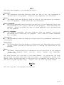
Note: Due to the new ATEX Directive in Europe, all references in this document to "Ex"
or "EEx" for intrinsic safety approvals should be disregarded effective 7/1/03 within the
member countries of the European Union (EU). At this time, this product is not approved
in accordance with the new ATEX Directive and is not sold for use in hazardous
atmospheres or explosive zones by customers within the EU. Outside of the EU, all
references to intrinsic safety continue without change.
56-200
04/97
Rev. F
TABLE OF CONTENTS
INTRODUCTION . . . . . . . . . . . . . . . . . . . . . . . . . . . . . . . . . . . . . . . . . . . . . . . . . . . . . . . . . . . . . . . . . . . . . . . . . . . . . . . .
1
BATTERY INSTALLATION . . . . . . . . . . . . . . . . . . . . . . . . . . . . . . . . . . . . . . . . . . . . . . . . . . . . . . . . . . . . . . . . . . . . . . . . .
2
CABLE REMOVAL OR ATTACHMENT . . . . . . . . . . . . . . . . . . . . . . . . . . . . . . . . . . . . . . . . . . . . . . . . . . . . . . . . . . . . . . .
3
USING THE MICROPHONE BOOM . . . . . . . . . . . . . . . . . . . . . . . . . . . . . . . . . . . . . . . . . . . . . . . . . . . . . . . . . . . . . . . . . .
4
UP AND RUNNING . . . . . . . . . . . . . . . . . . . . . . . . . . . . . . . . . . . . . . . . . . . . . . . . . . . . . . . . . . . . . . . . . . . . . . . . . . . . . .
Turning the Q-100 On . . . . . . . . . . . . . . . . . . . . . . . . . . . . . . . . . . . . . . . . . . . . . . . . . . . . . . . . . . . . . . . . . . . . . .
Resetting the Q-100 . . . . . . . . . . . . . . . . . . . . . . . . . . . . . . . . . . . . . . . . . . . . . . . . . . . . . . . . . . . . . . . . . . . . . . . .
Turning the Q-100 Off . . . . . . . . . . . . . . . . . . . . . . . . . . . . . . . . . . . . . . . . . . . . . . . . . . . . . . . . . . . . . . . . . . . . . .
Starting and Stopping Data Collection . . . . . . . . . . . . . . . . . . . . . . . . . . . . . . . . . . . . . . . . . . . . . . . . . . . . . . . . . .
4
4
4
4
4
DISPLAYED DATA AND OPERATION . . . . . . . . . . . . . . . . . . . . . . . . . . . . . . . . . . . . . . . . . . . . . . . . . . . . . . . . . . . . . . . .
Overload Indication - OL . . . . . . . . . . . . . . . . . . . . . . . . . . . . . . . . . . . . . . . . . . . . . . . . . . . . . . . . . . . . . . . . . . . .
5
7
RECORDING EVENTS . . . . . . . . . . . . . . . . . . . . . . . . . . . . . . . . . . . . . . . . . . . . . . . . . . . . . . . . . . . . . . . . . . . . . . . . . . . .
7
PRINTER USE . . . . . . . . . . . . . . . . . . . . . . . . . . . . . . . . . . . . . . . . . . . . . . . . . . . . . . . . . . . . . . . . . . . . . . . . . . . . . . . . . .
Printer Connection . . . . . . . . . . . . . . . . . . . . . . . . . . . . . . . . . . . . . . . . . . . . . . . . . . . . . . . . . . . . . . . . . . . . . . . . .
Preparing to Print . . . . . . . . . . . . . . . . . . . . . . . . . . . . . . . . . . . . . . . . . . . . . . . . . . . . . . . . . . . . . . . . . . . . . . . . . .
7
7
8
SAMPLE PRINTOUT . . . . . . . . . . . . . . . . . . . . . . . . . . . . . . . . . . . . . . . . . . . . . . . . . . . . . . . . . . . . . . . . . . . . . . . . . . . . .
Header Section . . . . . . . . . . . . . . . . . . . . . . . . . . . . . . . . . . . . . . . . . . . . . . . . . . . . . . . . . . . . . . . . . . . . . . . . . . .
Calibration Section . . . . . . . . . . . . . . . . . . . . . . . . . . . . . . . . . . . . . . . . . . . . . . . . . . . . . . . . . . . . . . . . . . . . . . . . .
Parameters Section . . . . . . . . . . . . . . . . . . . . . . . . . . . . . . . . . . . . . . . . . . . . . . . . . . . . . . . . . . . . . . . . . . . . . . . .
Time Summary / Data Summary Section . . . . . . . . . . . . . . . . . . . . . . . . . . . . . . . . . . . . . . . . . . . . . . . . . . . . . . . .
Event Summary Section . . . . . . . . . . . . . . . . . . . . . . . . . . . . . . . . . . . . . . . . . . . . . . . . . . . . . . . . . . . . . . . . . . . .
Time History Section . . . . . . . . . . . . . . . . . . . . . . . . . . . . . . . . . . . . . . . . . . . . . . . . . . . . . . . . . . . . . . . . . . . . . . .
% Time Statistical Distribution Section . . . . . . . . . . . . . . . . . . . . . . . . . . . . . . . . . . . . . . . . . . . . . . . . . . . . . . . . .
Exceedance Levels Section . . . . . . . . . . . . . . . . . . . . . . . . . . . . . . . . . . . . . . . . . . . . . . . . . . . . . . . . . . . . . . . . . .
9
9
9
10
10
11
12
14
15
CALIBRATING THE Q-100 . . . . . . . . . . . . . . . . . . . . . . . . . . . . . . . . . . . . . . . . . . . . . . . . . . . . . . . . . . . . . . . . . . . . . . . . . 16
CHECKING THE Q-100 CALIBRATION . . . . . . . . . . . . . . . . . . . . . . . . . . . . . . . . . . . . . . . . . . . . . . . . . . . . . . . . . . . . . . . 18
CHECKING THE Q-100 BATTERY CONDITION . . . . . . . . . . . . . . . . . . . . . . . . . . . . . . . . . . . . . . . . . . . . . . . . . . . . . . . . 18
SPECIFICATIONS . . . . . . . . . . . . . . . . . . . . . . . . . . . . . . . . . . . . . . . . . . . . . . . . . . . . . . . . . . . . . . . . . . . . . . . . . . . . . . . 19
PRINCIPLES OF OPERATION . . . . . . . . . . . . . . . . . . . . . . . . . . . . . . . . . . . . . . . . . . . . . . . . . . . . . . . . . . . . . . . . . . . . .
General Characteristics . . . . . . . . . . . . . . . . . . . . . . . . . . . . . . . . . . . . . . . . . . . . . . . . . . . . . . . . . . . . . . . . . . . . .
Microphone Characteristics . . . . . . . . . . . . . . . . . . . . . . . . . . . . . . . . . . . . . . . . . . . . . . . . . . . . . . . . . . . . . . . . . .
Weighting Characteristics . . . . . . . . . . . . . . . . . . . . . . . . . . . . . . . . . . . . . . . . . . . . . . . . . . . . . . . . . . . . . . . . . . .
22
22
23
23
SECURITY . . . . . . . . . . . . . . . . . . . . . . . . . . . . . . . . . . . . . . . . . . . . . . . . . . . . . . . . . . . . . . . . . . . . . . . . . . . . . . . . . . . . . 24
TYPICAL OPERATING PROCEDURE . . . . . . . . . . . . . . . . . . . . . . . . . . . . . . . . . . . . . . . . . . . . . . . . . . . . . . . . . . . . . . . .
As a Personal Noise Dosimeter . . . . . . . . . . . . . . . . . . . . . . . . . . . . . . . . . . . . . . . . . . . . . . . . . . . . . . . . . . . . . . .
As an Environmental Monitor . . . . . . . . . . . . . . . . . . . . . . . . . . . . . . . . . . . . . . . . . . . . . . . . . . . . . . . . . . . . . . . . .
As a Survey Event Monitor . . . . . . . . . . . . . . . . . . . . . . . . . . . . . . . . . . . . . . . . . . . . . . . . . . . . . . . . . . . . . . . . . .
24
24
26
27
ACCURACY . . . . . . . . . . . . . . . . . . . . . . . . . . . . . . . . . . . . . . . . . . . . . . . . . . . . . . . . . . . . . . . . . . . . . . . . . . . . . . . . . . . .
Low Level Measurements . . . . . . . . . . . . . . . . . . . . . . . . . . . . . . . . . . . . . . . . . . . . . . . . . . . . . . . . . . . . . . . . . . .
Accuracy of Readings . . . . . . . . . . . . . . . . . . . . . . . . . . . . . . . . . . . . . . . . . . . . . . . . . . . . . . . . . . . . . . . . . . . . . .
Microphone Positioning . . . . . . . . . . . . . . . . . . . . . . . . . . . . . . . . . . . . . . . . . . . . . . . . . . . . . . . . . . . . . . . . . . . . .
Microphone Windscreen . . . . . . . . . . . . . . . . . . . . . . . . . . . . . . . . . . . . . . . . . . . . . . . . . . . . . . . . . . . . . . . . . . . .
Windscreen Attenuation . . . . . . . . . . . . . . . . . . . . . . . . . . . . . . . . . . . . . . . . . . . . . . . . . . . . . . . . . . . . . . . . . . . . .
28
28
28
29
30
30
TROUBLESHOOTING . . . . . . . . . . . . . . . . . . . . . . . . . . . . . . . . . . . . . . . . . . . . . . . . . . . . . . . . . . . . . . . . . . . . . . . . . . . . 31
ACCESSORIES . . . . . . . . . . . . . . . . . . . . . . . . . . . . . . . . . . . . . . . . . . . . . . . . . . . . . . . . . . . . . . . . . . . . . . . . . . . . . . . . .
Microphone . . . . . . . . . . . . . . . . . . . . . . . . . . . . . . . . . . . . . . . . . . . . . . . . . . . . . . . . . . . . . . . . . . . . . . . . . . . . . .
Windscreen . . . . . . . . . . . . . . . . . . . . . . . . . . . . . . . . . . . . . . . . . . . . . . . . . . . . . . . . . . . . . . . . . . . . . . . . . . . . . .
Data Interface Modules . . . . . . . . . . . . . . . . . . . . . . . . . . . . . . . . . . . . . . . . . . . . . . . . . . . . . . . . . . . . . . . . . . . . .
Printer . . . . . . . . . . . . . . . . . . . . . . . . . . . . . . . . . . . . . . . . . . . . . . . . . . . . . . . . . . . . . . . . . . . . . . . . . . . . . . . . . .
Questware Software . . . . . . . . . . . . . . . . . . . . . . . . . . . . . . . . . . . . . . . . . . . . . . . . . . . . . . . . . . . . . . . . . . . . . . .
Calibrator Adapters . . . . . . . . . . . . . . . . . . . . . . . . . . . . . . . . . . . . . . . . . . . . . . . . . . . . . . . . . . . . . . . . . . . . . . . .
Tripods . . . . . . . . . . . . . . . . . . . . . . . . . . . . . . . . . . . . . . . . . . . . . . . . . . . . . . . . . . . . . . . . . . . . . . . . . . . . . . . . . .
32
32
32
32
32
32
33
33
QUEST SERVICE AND WARRANTY POLICY . . . . . . . . . . . . . . . . . . . . . . . . . . . . . . . . . . . . . . . . . . . . . . . . . . . . . . . . . . 34
APPENDIX A
Glossary
APPENDIX B
Q100 Dosimeter Setup Software
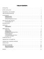
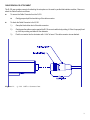
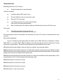
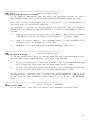
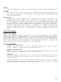
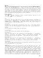
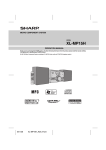
INTRODUCTION
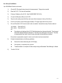
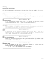
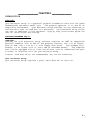
The Q-100 accumulates, calculates, and displays noise measurement data.
Figure 1.
Q-100 Noise Dosimeter.
1
The Q-100 can function as two simultaneous noise dosimeters (d1 and d2) operating with different thresholds.
The Q-100 functions as either a personal noise dosimeter, an environmental monitor or a survey event monitor.
#
When used as a Personal Noise Dosimeter:
The Q-100 may be clipped on a belt or worn in a shirt pocket. The small microphone is simply clipped to the
shirt or shirt collar near the ear.
#
When used as an Environmental Monitor or Events Monitor:
The Q-100 may be either hand held or mounted to a standard camera tripod. The microphone is connected
to the "Microphone Boom" and the unit is held as you would a sound level meter.
#
When used with a Printer:
The Q-100 can print detailed reports of noise events. It connects to a printer by using a Quest "Parallel Printer
Interface" or "Serial Computer Interface".
The Q100 DOSIMETER Setup Software allows the user to program the Q-100 from a personal computer.
BATTERY INSTALLATION
The battery must be a 9 Volt Alkaline type.
(Examples are: NEDA 1604A, IEC 6LF22, or IEC 6LR61)
#
2
Insert the battery into the battery compartment as follows:
1.)
Position the Q-100 so that the belt clip (back of the Q-100) is facing upwards.
2.)
The battery cover is fastened to the end of the Q-100 with a single captive Phillips screw. Use a screwdriver
to loosen the screw. Remove the battery cover.
3.)
View the battery terminal drawing on the back of the Q-100. Slide the battery into the battery compartment as
the drawing indicates.
4.)
Install the battery cover as follows:
A.)
Use the screwdriver to start the screw into the threaded opening in the Q-100.
B.)
As you tighten it, be sure that the two short posts on the inside of the cover align with the body of the
Q-100.
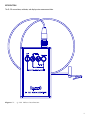
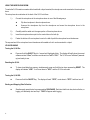
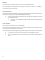
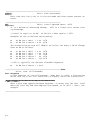
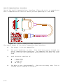
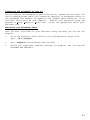
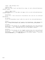
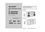
CABLE REMOVAL OR ATTACHMENT
The Q-100 uses a single connector for attaching the microphone or the serial or parallel data interface modules. Remove or
attach the Cable Connector as follows:
#
To remove the Cable Connector from the Q-100:
#
#
Gently grasp and pull the knurled ring of the cable connector.
To attach the Cable Connector to the Q-100:
1.)
Grasp the black rubber boot of the cable connector.
2.)
Gently press the cable connector against the Q-100 connector while slowly rotating it. When it is properly lined
up, it will stop rotating and slide into the dosimeter.
3.)
Push the connector into the dosimeter until a "click" is heard. The cable connector is now attached.
Figure 2.
Q-100 Cable Connection.
3
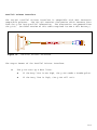
USING THE MICROPHONE BOOM
To make the Q-100 easier to use when either hand-held or tripod mounted, the microphone can be mounted on the microphone
boom.
The microphone boom attaches to the back of the Q-100 as follows:
1.)
Connect the microphone to the microphone boom in one of the following ways:
#
Clip the microphone to the microphone boom.
#
Unscrew the microphone clip from the microphone and screw the microphone boom to the
microphone.
2.)
Carefully wind the cable onto the upper portion of the microphone boom.
3.)
Insert the microphone boom pin into the center hole on the belt clip.
4.)
Fasten the bottom of the microphone boom to the belt clip with the microphone boom thumbscrew.
The exposed end of the microphone boom thumbscrew is threaded so that it can be mounted to a tripod.
UP AND RUNNING
Turning the Q-100 On:
#
Press and hold the ON/OFF Key for 1 second until the display lights. The display will briefly show the current
software revision "r2.xx", and then count down from "InI9" to "InI1". The Q-100 is now "initialized" (warmedup) and ready to use.
Resetting the Q-100:
#
To clear stored data from memory, simultaneously press and hold the two keys representing RESET. The
display will indicate "rES5". It will count down to "rES1" and the Q-100 is now reset.
Turning the Q-100 Off:
#
Press and hold the ON/OFF Key. The display will read "OFF5", count down to "OFF1" and then turn off.
Starting and Stopping Data Collection:
#
4
Simultaneously press the two keys representing RUN/PAUSE. Each time that this is done, data collection, or
logging, will alternately start and stop. "RUN" will appear while logging.
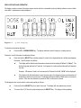
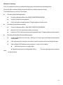
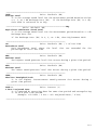
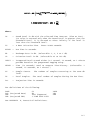
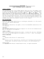
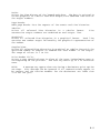
DISPLAYED DATA AND OPERATION
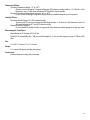
The display contains a central 4-character numeric section which is surrounded by various display indicators, some of which
show which measurement is being displayed.
Figure 3.
Q-100 Display.
To select the information displayed:
#
Press the UP or DOWN ARROW Key. The display indicators and will change in a rotating manner.
Dosimeter 1 and 2 information is selected as follows:
#
Each time that the SELECT key is briefly pressed, the data for the displayed function will alternate between
Dosimeter 1 and Dosimeter 2 as follows:
#
The Display will first indicate which dosimeter information will be displayed ("d1.xx" or "d2.xx"). The
last two digits (xx) indicate the Threshold. It will appear for a brief period and then will be followed by
the data.
Example: If Dosimeter 1 data is to be shown and its Threshold is 90 dB, "d1.90" will be displayed.
#
If the threshold for both dosimeters is set to the same value, the display for the second dosimeter will
instead show data for the current event. The display will be preceeded by "E xx" where xx is the event
number. Each time the dosimeter is placed into RUN, a new event is started.
The displayed value can be made to continuously update as follows:
#
Press and hold the SELECT Key for at least 3 seconds. The display will now update every second.
#
To remove the Q-100 from this mode, briefly press the SELECT Key. The display will stop updating.
5
The Data Functions (available for Dosimeters 1 and 2) are:
"DOSE"
"DOSE 8"
Dose
8 Hour Projected Dose
"LAVG"
Average Level with a 4, 5 or 6dB Exchange Rate
"LEQ" Average Level with a 3 dB Exchange Rate
"SPL"
Sound Pressure Level
"MAX" Maximum Level, weighted, with F or S time constant
"SEL"
Sound Exposure Level (3, 4, 5, 6 dB Exchange Rate)
"EXP"
Exposure (3 dB Exchange Rate only)
"TWA" Time Weighted Average
NOTE: See "APPENDIX A, Acoustical Definitions" for more detail about these functions.
The Security Feature, Run Time, Battery Indicator and Run appear as follows:
"SEC" Security Mode is ready to activate.
#
"xx:xx"
"Hr:xx"
"Hx:xx"
"xx:xx"
Only displayed if security mode has been activated by the Q100 DOSIMETER Setup software.
Total Run Time in Minutes : Seconds.
Total Run Time in Hours (if less than 100).
Total Run Time in Hours (if from 100 to 1000).
Total Run Time in Hours (if more than 1000).
#
"xx:xx" displayed if less than one hour of data has been logged.
#
"Hr:xx" only displayed if more than one hour of data has been logged.
#
"BAT"
Automatically appears when the battery is low.
#
"RUN"
6
Use the SELECT Key to alternate between Hours and Minutes/Seconds.
After first appearing, the battery is good for at least 8 more hours of operation.
Indicates that data logging is occurring.
Overload Indication - OL
If the sound pressure level exceeds the range of the instrument, "OL" will appear in the display, indicating an overload has
occurred. If this happens while in RUN, OL will remain in the display until the Q100 is reset. To view data after an OL occurs,
press and hold the SELECT key. (NOTE: newer model Q-100s have a separate OL indicator in the display, so that OL and data
may be viewed simultaneously.) OL conditions will appear on the printout as peaks of 113dB or greater on the low range, or
143dB or greater on the high range.
RECORDING EVENTS
The Q-100 will store up to 999 events. An Event will be stored each time that it is Run and Paused.
It is up to the operator to keep track of the location of each event as it is recorded.
Operate the Event Mode as follows:
#
Reset the Q-100. This clears all stored data.
#
Run and Pause the Q-100 for each Event. If the thresholds for dosimeters 1 and 2 are the same, the current
event data will be viewed instead of dosimeter 2.
#
Accumulate as many Events as desired.
#
Print directly from the Q-100 or use the Noise Manager software with a computer to review and/or print the
data.
PRINTER USE
Printer Connection:
The Q-100 can send data directly to a printer or personal computer. One of the following INTERFACE Modules is required:
#
PARALLEL PRINTER INTERFACE (Stk. # 056-957)
Converts the data to Parallel Printer compatability.
#
SERIAL COMMUNICATIONS INTERFACE (Stk. # 056-956 or
056-707)
Converts the data to RS-232 output for Serial Printer operation or downloading to a personal computer.
To connect the Q-100 to a printer:
1.)
Remove the microphone cable from the Q-100 as follows:
A.)
Grasp the knurled microphone cable connector and gently pull to remove the microphone cable.
7
2.)
3.)
Connect the PARALLEL PRINTER INTERFACE round cable connector to the Q-100 as follows:
A.)
Grasp the black rubber boot of the cable connector.
B.)
Gently press the connector against the Q-100 connector while slowly rotating it. When it is properly
lined up, it will stop rotating and slide into the dosimeter.
C.)
Push the connector into the dosimeter until a "click" is heard. The cable is now connected.
Insert the other cable connector (attached to the flat cable) into the printer.
When using a parallel printer there should be no additional setup required.
If a serial printer is used, it's data parameters must match that of the Q100 as follows:
9600 baud
1 Start bit
8 Data bits
1 Stop bit
No parity (disabled)
Preparing to Print
Use the Q-100 with a Printer as follows:
1.)
Accumulate data with the Q-100.
2.)
Place it in the Pause mode.
3.)
Remove the microphone from the Q-100 and connect the printer and appropriate Interface Module.
4.)
Turn on the printer and the Q-100.
5.)
Press the key combination for PRINT. "Prn" followed by "PAr" or SEr" will appear in the display. The printer
will begin to print data as described in the next section, SAMPLE PRINTOUT.
To abort a printout:
#
Press any key. "PAr" or SEr" will disappear from the display. The print function will halt.
NOTE: The printer may continue to print for several seconds after being aborted. If this is not
desired, shorten the length of the printer buffer (if possible). Consult the printer manual.
#
8
If you abort a printout, data stored in the Q-100 is not destroyed. Simply print again.
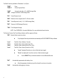
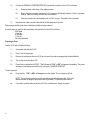
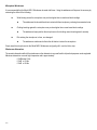
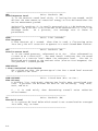
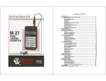
SAMPLE PRINTOUT
The following figures illustrate each section of the Printout.
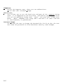
Header Section
Figure 4
The Header states the following:
#
The Model Number: (Q-100 Noise Logging Dosimeter)
#
The Unit Software Rev Level: (Unit Version Number: X.XX)
#
"Noise Manager" Software Rev Level: (Appears if used.)
#
The Serial Number: ( 2 Letters followed by 7 Digits)
The Header provides locations to write in the following data:
#
Name
#
Work Area
#
Comments
QUEST ELECTRONICS
Q-100 Noise Logging Dosimeter
Unit Version Number: 1.15
Serial Number: QA2050001
Name _____________________________________________________________________
Work Area ________________________________________________________________
Comments _________________________________________________________________
__________________________________________________________________________
__________________________________________________________________________
Figure 4.
Header Printout.
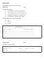
Calibration Section
Figure 5
The Calibration is printed out as follows:
Dosimeter Calibration:
Pre-survey
114.0dB
Calibrator:
Serial Number ___________________
Calibration Date ___________________
Figure 5.
12-JAN-93 @ 02:46:51PM
Calibration Printout.
9
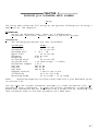
Parameters Section
Figure 6
The Parameters for Dosimeter 1 and Dosimeter 2 are printed out as follows:
Auto Settings:
Auto-On Disabled Mode - Daily
Time 12:00:00PM Duration 00:01 H:M
Dosimeter 1 Parameters:
Range
70-140dB
Criterion
90dB
Prj Period
8.00H
Weighting
Threshold
Upper Limit
A
80dB
115dB
Time Constant
Exchange Rate
Slow
5dB
Dosimeter 2 Parameters:
Range
70-140dB
Criterion
90dB
Prj Period
8.00H
Weighting
Threshold
Upper Limit
A
90dB
115dB
Time Constant
Exchange Rate
Slow
5dB
Figure 6.
Setup Printout.
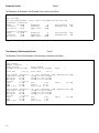
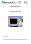
Time Summary / Data Summary Section
Figure 7
The Summary Printout (Time Summary / Data Summary) is printed out as follows:
Time Summary:
Number of Events
1
Event Started
12-JAN-93 @ 02:55:10PM
Event Stopped
12-JAN-93 @ 03:01:00PM
Total Run
Total Pause
0:05:49
Event
1
0:17:13
Data Summary [Dosimeter 1, A / Slow, Threshold 80dB, Exchange Rate 5dB]
Peak Level 108.8dB
12-JAN-93 @ 02:56:00PM
Max Level
98.4dB
12-JAN-93 @ 02:56:45PM
Min Level
58.3dB
12-JAN-93 @ 03:00:58PM
UL Time
0:00:00
Lavg
79.7dB
Dose
0.29%
SEL(5)
121.9dB
TWA
47.9dB
Dose[8]
23.93%
TWA[ 8.00]
79.7dB
Dose[ 8.00] 23.93%
Data Summary [Dosimeter 2, A / Slow, Threshold 90dB, Exchange Rate 5dB]
Peak Level 108.8dB
12-JAN-93 @ 02:56:00PM
Max Level
98.4dB
12-JAN-93 @ 02:56:45PM
Min Level
58.3dB
12-JAN-93 @ 03:00:58PM
UL Time
0:00:00
Lavg
71.5dB
Dose
0.09%
SEL(5)
113.8dB
TWA
39.7dB
Dose[8]
7.42%
TWA[ 8.00]
71.5dB
Dose[ 8.00]
7.42%
Figure 7.
10
Time Summary / Data Summary Printout.
Event Summary Section
Figure 8
Each time that the Q-100 is Run and Paused, an event is stored in memory. When printing, an Event Summary Printout will
automatically occur as follows:
Each Event Summary is computed for the Run Time of each event.
Event Summaries are printed as follows:
Event
1
Name _____________________________________________________________________
Work Area ________________________________________________________________
Comments _________________________________________________________________
__________________________________________________________________________
__________________________________________________________________________
Event Started
12-JAN-93 @ 02:55:10PM
Run Time
Event Stopped
12-JAN-93 @ 03:01:00PM
0:05:49
Data Summary [Dosimeter 1, A / Slow, Threshold 80dB, Exchange Rate 5dB]
Peak Level 108.8dB
12-JAN-93 @ 02:56:00PM
Max Level
98.4dB
12-JAN-93 @ 02:56:45PM
Min Level
58.3dB
12-JAN-93 @ 03:00:58PM
Lavg
79.7dB
Dose
0.29%
SEL(5)
121.9dB
TWA
47.9dB
Dose[8]
23.93%
TWA[ 8.00]
79.7dB
Dose[ 8.00] 23.93%
Data Summary [Dosimeter 2, A / Slow, Threshold 90dB, Exchange Rate 5dB]
Peak Level 108.8dB
12-JAN-93 @ 02:56:00PM
Max Level
98.4dB
12-JAN-93 @ 02:56:45PM
Min Level
58.3dB
12-JAN-93 @ 03:00:58PM
Lavg
71.5dB
Dose
0.09%
SEL(5)
113.8dB
TWA
39.7dB
Dose[8]
7.42%
TWA[ 8.00]
71.5dB
Dose[ 8.00]
7.42%
Figure 8.
Event Summary Printout.
11
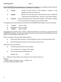
Time History Section
Figure 9
The Q100 DOSIMETER Setup Software allows you to determine which information is to be logged for printing at a later time.
Each Dosimeter will produce Time Histories based on the selection of the following:
#
"Log Avg"
Average Time History will print for either Dosimeter 1, dosimeter 2, or both
(depending on how the Q-100 was set up).
#
"Log Max"
Maximum Level Time History will print. Note that both Dosimeter 1 and Dosimeter
2 will always have the same Max Levels. Therefore, only one printout will appear.
#
"Log Peak"
Peak Level Time History will print. Note that both Dosimeter 1 and Dosimeter 2 will always
have the same Peak Levels. Therefore, only one printout will appear.
The Logging Interval (Time per Sample) is entered with the Q100 DOSIMETER Setup Software to be one of the following:
#
#
#
"1 second"
1 Second / Sample
"10 seconds" 10 Seconds / Sample
"1 minute"
1 Minute / Sample
Time Histories can be printed in either a Tabular or Graphical Format based on the selection you make with the Q100
DOSIMETER Setup Software. The length (and resolution) of the printout can be changed with the Setup Software by selecting
Samples / Line and changing the number from 1 to 120.
Time per Line appears on the printout and is defined as follows:
#
When printing Tabular information, it is the time between each value as it is printed moving left to right.
#
When printing Graphical information, it is the time between each line of type.
Calculate the Time per Line as follows:
#
The dosimeter logs information as Time per Sample.
(1 Sec / Sample) (10 Sec / Sample) (1 Min / Sample)
#
The Printout is programmed as Samples per Line:
(Samples / Line)
#
(1 to 120)
Multiply the "Time per Sample" by the "Samples per Line" to get the "Time per Line".
EXAMPLE:
(1 Minute / Sample) X (10 Samples / Line) = 10 Minutes / Line
A Time History Printout will appear as follows:
12
TABULAR FORMAT
Lavg TIME HISTORY [Dosimeter 1]
Weighting
A
Time Constant Slow
Threshold 80dB
Exchange Rate 5dB
1
(Sec)
12-JAN-93
Time
02:55:10PM
02:55:15PM
Lavg
87.6dB
88.4dB
Max TIME HISTORY
Weighting
A
1
(Sec)
12-JAN-93
Time
02:55:10PM
02:55:15PM
84.6dB
85.5dB
84.7dB
83.7dB
88.0dB
87.1dB
1
Page
1
Page
1
Page
1
89.0dB
87.9dB
Time Constant Slow
Max
88.2dB
89.0dB
86.7dB
87.5dB
86.6dB
84.3dB
88.9dB
88.3dB
89.8dB
88.4dB
Peak TIME HISTORY
1
(Sec)
12-JAN-93
Time
02:55:10PM
02:55:15PM
Page
Peak
100.7dB
106.7dB
100.7dB
106.7dB
102.0dB
104.2dB
102.0dB
100.4dB
101.9dB
100.9dB
GRAPHICAL FORMAT
Lavg TIME HISTORY [Dosimeter 1]
Weighting
A
Time Constant Slow
Threshold 80dB
Exchange Rate 5dB
1
(Sec)
12-JAN-93
Time
02:55:10PM
02:55:11PM
02:55:12PM
Lavg
87.6dB
84.6dB
84.7dB
Max TIME HISTORY
Weighting
A
1
(Sec)
12-JAN-93
Time
02:55:10PM
02:55:11PM
02:55:12PM
40
60
80
100
120
140
+----+----+----+----+----+----+----+----+----+----+
************************
***********************
***********************
Page
Max
88.2dB
86.7dB
86.6dB
40
60
80
100
120
140
+----+----+----+----+----+----+----+----+----+----+
=========================
========================
========================
Peak TIME HISTORY
1
(Sec)
12-JAN-93
Time
02:55:10PM
02:55:11PM
02:55:12PM
Peak
100.7dB
100.7dB
102.0dB
Note:
Figure 9.
1
Time Constant Slow
Page
1
40
60
80
100
120
140
+----+----+----+----+----+----+----+----+----+----+
-------------------------------------------------------------------------------------------These printouts have been shortened to save space.
Time History Printout.
13
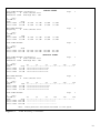
% Time Statistical Distribution Section
Figure 10
The % Time Statistical Distribution will appear as follows:
% TIME STATISTICAL DISTRIBUTION
Weighting
A
Time Constant Slow
Total Samples
Total Run
dB
58
59
60
61
62
63
64
65
66
67
68
69
70
71
72
73
74
75
76
77
78
79
80
81
82
83
84
85
86
87
88
89
90
91
92
93
94
95
96
97
98
dB
14
1
11198
0:05:49
Samples
60
83
74
172
123
146
33
10
70
45
48
202
494
653
668
1064
733
612
809
472
245
254
288
286
435
449
441
401
414
361
305
167
139
142
113
62
49
21
18
25
12
Samples
Figure 10.
Page
% Time
0.53%
0.74%
0.66%
1.53%
1.09%
1.30%
0.29%
0.08%
0.62%
0.40%
0.42%
1.80%
4.41%
5.83%
5.96%
9.50%
6.54%
5.46%
7.22%
4.21%
2.18%
2.26%
2.57%
2.55%
3.88%
4.00%
3.93%
3.58%
3.69%
3.22%
2.72%
1.49%
1.24%
1.26%
1.00%
0.55%
0.43%
0.18%
0.16%
0.22%
0.10%
% Time
0
20
40
60
80
100
+----+----+----+----+----+----+----+----+----+----+
*
*
*
*
*
*
*
*
*
*
*
*
***
***
***
*****
****
***
****
***
**
**
**
**
**
***
**
**
**
**
**
*
*
*
*
*
*
*
*
*
*
+----+----+----+----+----+----+----+----+----+----+
0
20
40
60
80
100
% Time Statistical Distribution Printout.
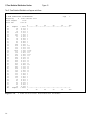
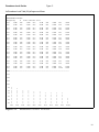
Exceedance Levels Section
Figure 11
An Exceedance Level Table (LN) will appear as follows:
EXCEEDANCE LEVELS
Weighting
A
Time Constant Slow
L01
L06
94dB
89dB
L02
L07
92dB
88dB
L03
L08
91dB
88dB
L04
L09
90dB
88dB
L05
L10
90dB
87dB
L11
L16
87dB
86dB
L12
L17
87dB
85dB
L13
L18
86dB
85dB
L14
L19
86dB
85dB
L15
L20
86dB
84dB
L21
L26
84dB
83dB
L22
L27
84dB
83dB
L23
L28
84dB
82dB
L24
L29
83dB
82dB
L25
L30
83dB
82dB
L31
L36
82dB
80dB
L32
L37
81dB
79dB
L33
L38
81dB
79dB
L34
L39
81dB
79dB
L35
L40
80dB
78dB
L41
L46
78dB
76dB
L42
L47
77dB
76dB
L43
L48
77dB
76dB
L44
L49
77dB
76dB
L45
L50
77dB
76dB
L51
L56
76dB
75dB
L52
L57
76dB
75dB
L53
L58
75dB
75dB
L54
L59
75dB
74dB
L55
L60
75dB
74dB
L61
L66
74dB
73dB
L62
L67
74dB
73dB
L63
L68
74dB
73dB
L64
L69
74dB
73dB
L65
L70
73dB
73dB
L71
L76
73dB
72dB
L72
L77
73dB
72dB
L73
L78
73dB
72dB
L74
L79
73dB
72dB
L75
L80
72dB
72dB
L81
L86
71dB
71dB
L82
L87
71dB
70dB
L83
L88
71dB
70dB
L84
L89
71dB
70dB
L85
L90
71dB
70dB
L91
69dB
L92
69dB
L93
67dB
L94
64dB
L95
63dB
L96
62dB
L97
61dB
L98
61dB
L99
59dB
L100
58dB
___________________________________________________________________
140
130
120
110
100
90
80
70
60
50
40
*
*
*
*
*
*
*
*
*
*
*
L01
*
*
*
*
*
*
*
*
*
*
L10
Figure 11.
*
*
*
*
*
*
*
*
*
L20
*
*
*
*
*
*
*
*
*
L30
*
*
*
*
*
*
*
*
L40
*
*
*
*
*
*
*
*
L50
*
*
*
*
*
*
*
L60
*
*
*
*
*
*
*
L70
*
*
*
*
*
*
*
L80
*
*
*
*
*
*
*
L90
*
*
*
*
L100
Exceedance Levels Printout.
15
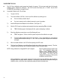
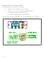
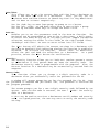
CALIBRATING THE Q-100
#
The Q-100 has a calibration sound pressure level stored in its memory. This level must match that of the Acoustic
Calibrator used to calibrate the instrument. The Q-100 has this level factory set to 114.0dB. Use the Q100
DOSIMETER Setup software to change this level.
#
Acoustically Calibrate the Q-100 as follows:
1.)
Turn the Q-100 On.
2.)
Turn on the calibrator (1000 Hz). Listen to see if the calibrator is producing a tone.
#
If a tone is heard, proceed to step 3.
#
If no tone is present, see the calibrator's manual to correct the problem.
3.)
Insert the Microphone and Adapter into the calibrator. (See Figure 12.)
4.)
Start the CAL Process by simultaneously pressing the two keys representing CAL on the label.
#
5.)
"CAL" will briefly appear in the display while the system is attempting to calibrate.
When the calibration process is done, one of the following will occur:
#
"FAIL" may appear. If it does, check the system and perform the calibration over again.
#
The actual calibrator dB level will appear on the display. To be a valid calibration, it must match the
computer-entered calibrator level by +/- 0.1 dB. If not, check the system and perform the calibration
over again.
6.)
After a successful calibration, the Q-100 will be operating in the SPL mode.
#
The Sound Level Calibrator output will be affected slightly due to altitude (atmospheric pressure). Therefore,
if calibrating at high altitudes, see the calibrator manual for altitude correction values.
NOTE: During calibration the A weighted SPL and C weighted
SPL are measured and set equal to each
other. The unweighted logging peak
detector is also calibrated, setting its
output at 3dB above the RMS level shown
in the display. The Q100 must be
calibrated at a frequency of 1kHz, as this
condition is only true at 1kHz.
As the peak detector is most accurate over the upper portion of the range, the calibration value should be in
the upper 40dB of the range used for calibration. It is important to not disturb the microphone during the
calibration routine, as this may cause a high peak reading and result in bad peak data.
16
Figure 12.
Calibrating the Microphone Sensitivity.
The Q-100 will maintain its accuracy for many months of use.
However, it is recommended that the unit be returned once a year to a Quest Authorized Service Station for a complete checkout
and recalibration.
Accurate calibration standards are maintained and used by Quest. They are traceable to the National Institute of Standards
and Technology (NIST).
17
CHECKING THE Q-100 CALIBRATION
It is recommended that the Q-100 calibration be checked before and after each use. This will verify that the unit was in
calibration between the checks.
Check the Q-100 Calibration as follows:
1.)
Place the unit into the Pause mode.
2.)
Turn on the calibrator (1000 Hz). Listen to see if the calibrator is producing a tone.
#
If a tone is heard, proceed to step 4.
#
If no tone is present, see the Calibrator Manual to correct the problem.
3.)
Insert the Microphone and Adapter into the Calibrator.
4.)
Read the SPL dB value. It should match the calibrator level by +/- 0.5 dB. If it does, the Q-100 is still in
calibration.
NOTE:
If the Q100 is being operated in the (40 dB - 110 dB) range
and the calibrator is a 114 dB model, this step may
not be be
possible due to the overrange of the calibrator. A 94 dB calibrator is better suited for low range calibration
and
check.
CHECKING THE Q-100 BATTERY CONDITION
18
#
If the lower left corner of the display indicates "BAT", the battery is low and should be replaced.
#
If the lower left corner of the display starts to indicate "BAT" during a measurement period, the battery will be
able to operate the unit for at least 8 more hours.
SPECIFICATIONS
Standards:
ANSI S1.25 - 1991
ANSI S1.4 - 1983, type 2
IEC 651 - 1979, type 2
IEC 804 - 1985, type 2
IEC 1252 - 1993
Detector:
True RMS
Frequency Weighting Networks:
"A" and "C" Weighting.
Response:
"SLOW" or "FAST" Response.
Pulse Range:
63 dB from 80 dB (RMS) to 143 dB (Peak)
Measuring Range:
All "A" or "C" Weighted SPL's from 70 dB to 140 dB (143 dB Peak) or from 40 dB to 110 dB (113 dB Peak) depending
upon range, will be measured. Note that the highest RMS dB level that can be measured will vary with the Crest Factor
of the SPL being measured. For example, with a Crest Factor of 20 dB, the highest RMS dB level that can be measured
is 120 dB.
Unweighted Peak SPL's are measured either from 100 dB to 143 dB or from 70 dB to 113 dB depending upon the range
setting.
Reference Range / Linearity Range / Primary Indicator Range:
Total Dynamic Range of 70 to 140 dB, High Range (Sinusoidal Signal) or 40 to 110 dB, Low Range (Sinusoidal Signal).
Type 2 accuracies apply to these Dynamic Ranges.
Level Linearity:
Within the Primary Indicator Range, referenced from the Reference SPL (114 dB), tested with a sinusoidal input signal,
it is within +/- 0.7 dB.
Microphone:
8mm Shoulder-Mount, Type 2 (with cable and connector)
Reference SPL:
114 dB
Reference Frequency:
1 kHz
Calibration at the Reference SPL and Reference Frequency:
Performed with an acoustic calibrator.
114 dB (Reference SPL) at 1 kHz (Reference Frequency).
#
Note that other Reference SPL's can be used (preferably between 90 dB and 115 dB), but the
Reference Frequency must always be 1 kHz.
See "CALIBRATING THE Q-100" for more detail.
19
Reference Direction:
The microphone used on the Q-100 is a Random Incidence (Diffuse Field) type. The angle of incidence is 70o.
Warm-Up and Settling Time:
10 seconds. The display will count down from "ini9" to "ini1" at unit turn-on. Warm-Up and Settling occur during the
count down.
Fixed Integration Periods:
Normally, the Q-100 integrates over the period that is desired. However, it can be programmed by the user for a fixed
integration period (Timed Run). This period can be set in 1 minute increments from 1 minute to 99 hours and 59
minutes.
Integration Time:
Signal dependent: With a 3dB exchange (doubling) rate and a constant level of 140dB the integration time would be
62 hours. As the signal level decreases and the exchange rate increases, the integration time increases to 145 hours
max.
Display:
Liquid Crystal Display, 4 Digits with the following Annunciators:
BAT, RUN, DOSE, 8, LAVE, 3, SPL, MAX, SEL, EXP, and TWA.
Data Output:
Uses Interface Modules to condition the data.
Baud: 9600
Connector: Uses the microphone connector to communicate with each Interface Module.
See the APPENDIX A for more information on:
Parallel Printer Interface
Serial Communications Interface
Battery:
Single 9-volt alkaline.
Battery Life:
Approximately 45 Hours. Shelf life is approximately 4 months due to memory and clock requirements.
Battery Test:
"BAT" appears in the display when the battery is low. From the first indication, the battery will operate the unit for at
least 8 more hours.
Memory and Clock/Calendar Battery Backup:
Lithium cell, 2 to 3 year life not including time that the 9 volt battery is removed. For long life, keep a good 9 volt battery
installed.
(Replacement only by Authorized Service Center)
20
Temperature Effects:
Operating Temperature Range: -10o to +50oC
Accuracy over the Operating Temperature Range (at 65% relative humidity) is within +/- 0.5 dB of the 1 kHz
Reference Level (114 dB) when calibrated at 20oC and 65% relative humidity.
Storage Temperature Range (battery removed): -20o to +60oC
Do not exceed the Storage Temperature Range because possible damage to the unit may result.
Humidity Effects:
Operating Humidity Range: 30 to 90% relative humidity.
Accuracy (at 40oC) over the Operating Humidity Range is within +/- 0.5 dB of the 1 kHz Reference Level (114
dB) when calibrated at 40oC and 65% relative humidity.
Maximum Humidity Limitation:
Do not exceed 95% relative humidity for long periods of time because possible damage to the unit may result.
Electromagnetic Field Effects:
Negligible below 50 Oersteds at 50 to 60 Hz.
Tested for RF susceptibility with < 1dB error at field strengths to 10 V/m over the frequency range of 10 MHz to 500
MHz.
Size:
4.5 x 2.8 x 1.0 inches (114 x 71 x 26 mm)
Weight:
11.5 ounces (326 grams) including microphone.
Construction:
Extruded aluminum housing, fully immersible.
21
PRINCIPLES OF OPERATION
General Characteristics
The Q-100 utilizes low power state-of-the-art circuitry. The Q-100 is very stable and reliable over a wide range of environmental
conditions.
The low power circuitry gives the unit a long battery life. When the battery is changed, all stored information is retained due to
an internal Lithium battery. The Lithium battery lasts for many years before needing replacement. (See SPECIFICATIONS)
A Keypad is used to select and display various data. To program various parameters, the Q-100 uses a personal computer with
Quest Q100 DOSIMETER Setup Software.
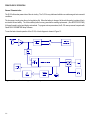
To see the basic internal operation of the Q-100, a block diagram is shown in Figure 13.
Figure 13.
22
Block Diagram of the Q-100.
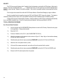
Microphone Characteristics
The Q-100 Noise Dosimeter uses an 8 mm omnidirectional ceramic microphone. It is buffered by a high impedance FET input
stage. (See Figure 14.)
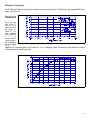
Weighting
Characteristics
The Q-100 has
both "A" and "C"
weighting
characteristics
as shown in
Figure 15. For
most industrial
and community
n o i s e
measurement
requirements,
the "A" weighting
should be used. Figure 14. Q-100 Microphone Frequency Response.
T h e
" A "
weighting has a response similar to the human ear. The "C" weighting is used for measuring noise reduction in hearing
protectors and other scientific purposes.
Figure 15.
A and C Weighting.
23
SECURITY
The Q100 has a security feature which, if enabled, locks the dosimeter controls while in RUN unless a 4 digit code is
entered. If secured, the display will show "____". To disable the security, use the arrow keys to set the first digit and press
SELECT to enter that digit. Repeat for the next three digits. If the code is successfully entered, the dosimeter will function
normally.
The four digit code is entered from either the Q100 Setup software or Quest Noise Manager pc support software.
Security is enabled from the keypad by placing the Q100 into RUN while "SEC" shows in the display. This display is
reached by pressing the arrow keys, but is only available if security has been enabled through the software package.
Another security option involves the Auto-On feature. Using the software, the Q100 may be configured to automatically
turn on and RUN at a specific time. If Auto-On Security has been selected, it will be secured while it is in RUN.
TYPICAL OPERATING PROCEDURE
As a Personal Noise Dosimeter
24
1.)
Use the computer and Q100 DOSIMETER Setup software to check the Q-100 setup. Be sure that it is proper
for the application. Change where needed.
2.)
Reset the Q-100.
3.)
Perform a Calibration of the Q-100. (See CALIBRATING THE Q-100.)
4.)
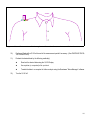
Attach the microphone to the operator's shirt as shown in Figure 16. Keep it high on the shoulder and away
from the neck as far as practical.
5.)
Simultaneously press the two keys representing RUN/PAUSE to place the Q-100 into the RUN mode.
6.)
Attach the unit to the operator's belt or pocket.
7.)
At the end of the measurement period, remove the unit from the operator's belt or pocket.
8.)
Simultaneously press the two keys representing RUN/PAUSE to place the Q-100 into the PAUSE mode.
9.)
Remove the Q-100 and microphone from the operator.
Figure 16.
Placement of Microphone When Used as a Personal Monitor.
10.)
Perform a Check of the Q-100 at the end of the measurement period if necessary. (See CHECKING THE Q100 CALIBRATION.)
11.)
Evaluate the desired data by the following method(s):
12.)
#
Read out the desired data using the Q-100 Display.
#
Use a printer (or computer) to list a printout.
#
Transfer the data to a computer for further analysis using the Questware "Noise Manager" software.
Turn the Q-100 off.
25
As an Environmental Monitor
Use the Q-100 as an Environmental Monitor as follows:
1.)
Use the computer and Q100 DOSIMETER Setup software to check the Q-100 setup. Be sure that it is proper
for the application. Change where needed.
2.)
Perform a Calibration of the Q-100. (See CALIBRATING THE Q-100.)
3.)
Connect the Microphone Boom to the Q-100.
4.)
Wrap the cable neatly around the Boom and connect the microphone to the top of the Boom.
5.)
Attach the unit to a tripod if desired.
6.)
Point the microphone upward forming approximately a 70 degree angle with the noise source.
7.)
Reset the Q-100.
8.)
Simultaneously press the two keys representing RUN/PAUSE to place the Q-100 into the RUN mode.
9.)
Perform the measurement for the desired time period.
10.)
Simultaneously press the two keys representing RUN/PAUSE at the end of the period to place the Q-100 into
the PAUSE mode.
11.)
Perform a Check of the Q-100 at the end of the measurement period if necessary. (See CHECKING THE Q100 CALIBRATION.)
12.)
Evaluate the desired data by the following method(s):
13.)
26
#
Read out the desired data using the Q-100 Display.
#
Use a printer (or computer) to list a printout.
#
Transfer the data to a computer for further analysis using the Questware "Noise Manager" software.
Turn the Q-100 off.
As a Survey Event Monitor
Up to 999 different Events can be stored.
1.)
Check all Q-100 setups that are relevant to the measurement. Change where needed.
2.)
Reset the Q-100. This clears all stored data.
3.)
Perform a Calibration of the Q-100. (See CALIBRATING THE Q-100.)
4.)
Connect the Microphone Boom to the Q-100.
5.)
Wrap the cable neatly around the Boom and connect the microphone to the top of the Boom.
6.)
Point the microphone upward forming approximately a 70 degree angle with the noise source.
7.)
Run and Pause the Q-100 for each event location as needed. Accumulate as many Events as desired.
1st Location:
2nd Location:
etc.
#
Event will be # 1.
Event will be # 2.
Event data is only displayed in the Q-100 if both dosimeters have the same threshold. Then the event
data will be displayed instead of dosimeter 2. Otherwise it only will appear in the printout. Therefore,
as measurements are made, list each location along with its associated event number.
Be sure that a representative sample of noise in each location has been accumulated.
8.)
9.)
Evaluate the desired data by the following method(s):
#
Read out the desired data using the Q-100 Display.
#
Use a printer (or computer) to list a printout.
#
Transfer the data to a computer for further analysis using the Questware "Noise Manager" software.
Turn the Q-100 off.
27
ACCURACY
For maximum accuracy, it is important to use the Q-100 correctly and to understand its limitations.
It will correctly integrate all sound levels within its operating ranges of 70 to 140 dB or 40 to 110 dB ("A" or "C" Weighting).
A few items related to accuracy are as follows:
Low Level Measurements
The Q-100 will accurately measure and display "A" and "C" weighted SPL down to the bottom of the selected measuring range.
Values below this are displayed as "LO". (See SPECIFICATIONS, Measuring Range.)
#
Functions such as TWA and LEQ are computed from SPL's. Since these are computed values, they can read
below 70 dB and still be valid.
#
For example, a 1 hour LAVG (5dB Exchange Rate) of 75 dB will calculate to (and be displayed as) a
TWA of 60 dB.
Accuracy of Readings
There is a tendency to overestimate the accuracy of digital readings.
The values (such as LEQ) are computed to a precision of 0.1 dB. However, the absolute accuracy of the reading is not 0.1 dB,
but is accurate to the overall stated tolerance of the instrument.
The 0.1 dB resolution is useful in determining the minimum sample time required to get an accurate short term measurement.
28
#
If, for example, the Leq is fluctuating 0.3 dB every second, then a longer sample time is required.
#
If the Leq is remaining stable from second to second within a few tenths of a dB, then the sample time is long
enough.
Microphone Positioning
The Q-100 measures sound most accurately without the presence of sound reflecting or absorbing objects.
Any near-by object or surface (including the operator) will act as a reflector or absorber of sound.
To minimize these errors, use the Q-100 as follows:
#
#
#
When taking Hand-Held measurements:
#
Connect the Microphone Boom. (See USING THE MICROPHONE BOOM.)
#
Hold the Q-100 with your arm extended.
#
Point the microphone upwards at about a 70 degree angle from the noise source.
When taking Tripod-Held measurements:
#
Connect the Microphone Boom. (See USING THE MICROPHONE BOOM.)
#
Mount the Q-100 to the tripod mount located on the belt clip.
#
Position the Q-100 so that the microphone points upwards at about a 70 degree angle from the noise source.
When taking Personal Noise Dosimeter Measurements:
#
Connect the Microphone to the shirt collar. (See Figure 16.) Keep it high on the shoulder and away from the
neck if possible.
#
If the noise seems to be coming from one location, place the microphone near the ear facing that location.
#
Keep the Model WS-5 Windscreen on the microphone. It helps to do the following:
#
levels
holds the microphone in an upright position.
# keeps the microphone from brushing against clothing.
This can produce higher than normal noise
into the microphone.
29
Microphone Windscreen
It is recommended that the Model WS-5 Windscreen be used at all times. Using the windscreen will improve the accuracy by
minimizing the effect of the following:
#
Wind blowing across the microphone can produce higher than normal sound level readings.
#
#
Clothing brushing against the microphone can produce higher than normal sound level readings.
#
#
The windscreen blocks wind from direct contact with the microphone, producing less unwanted noise.
The windscreen helps position the microphone so that clothing cannot brush against it as easily.
Dirt entering the microphone, in time, can damage it.
#
The windscreen catches and collects this dirt before it enters the microphone.
Simply insert the microphone into the Model WS-5 Windscreen and gently pull it over the Velcro strip.
Windscreen Attenuation
The acoustic attenuation effect of the windscreen on the dosimeter is very small and for all practical purposes can be neglected.
Maximum attenuation occurs at high frequencies and is approximately:
0.0 dB below 2 kHz
0.3 dB at 5 kHz
0.5 dB at 8 kHz
30
TROUBLESHOOTING
Blank display when the Q-100 is turned on:
#
Change the battery with a known fresh battery.
Unit does not calibrate:
#
Low Battery Indicator (BAT) must not be on.
#
Check the Calibrator; Listen for a tone from its output.
#
Reset the Q-100 and try again.
#
Try a different microphone if you have another dosimeter.
If this works the microphone needs replacing.
#
Make sure that the level of the calibrator matches the calibration level stored in the Q-100's memory.
Unit is erratic:
#
Try another microphone if you have another unit.
(The microphone could be intermittent, loose cable, etc.)
If the above attempts to restore normal operation are unsuccesful, return the Q-100 to Quest or an authorized service center
for service.
Memory Warning Messages
At turn on, the display normally briefly displays the software revision "r2.xx" followed by an initialization countdown
"InI8", "InI7", etc. If, instead of "InIx", "dFxx" is displayed, some setup information has been lost, probably due to a weak
internal memory backup battery. The battery should be replaced by an authorized Quest service center.
dF1x indicates that the peak calibration values have been lost, resulting in inaccurate peak readings.
dF2x indicates that the serial number has been lost. The serial number may be re-entered in memory by sending the command
#SAQxxxxxxxx (where xxxxxxxx is the remainder of the unit's serial number) via the serial interface module. A communications
package such as Procomm or Windows Terminal may be used.
dF4x indicates that the dosimeter setup information has been lost. Setup has reverted back to factory default settings. Check
setup parameters via the Q-100 setup program before performing a study.
dF3x indicates that both 1 and 2 have occurred.
dF5x indicates that both 1 and 4 have occurred.
dF6x indicates that both 2 and 4 have occurred.
dF7x indicates that 1, 2 and 4 have occurred.
31
ACCESSORIES
Microphone
56-963 8mm Shoulder-Mount Q-100 Dosimeter Microphone, Type 2 (with cable and connector)
56-830 Clothing Clips, package of 5, for microphone cable.
58-852 Earloops to hold microphone at the ear(10 per pack)
Windscreen
58-452 WS-5 Windscreen (8mm I.D.), package of 10.
Data Interface Modules
56-957 Parallel Printer Interface
(Centronics Compatible)
56-956 Serial Communications Interface (older version)
(25-pin, RS-232 Female)
#
Powered by either:
#
(One 9 Volt Battery, included)
#
(MODEL 920 AC Power Supply, not included)
56-707 Serial Communications Interface (newer,self powered)
Printer
80 Column Parallel Printer, 110 volt only.
Questware Software
#
All of the following software includes the Serial Communications Interface, 56-956 or 56-707
56-236 "Set-Up" Software (5.25" Floppy)
56-235 "Set-Up" Software (3.5" Floppy)
"Questsuite For Windows" PC support software
Calibrator Adapters
58-839 Calibrator Adapter (8 mm Mic. to 1 1/8 inch Coupler) Fits CA-12, CA-15, CA-22, CA-32
56-989 Calibrator Adapter (8 mm to 1 inch) Fits QC-10, QC-20
Tripods
59-045 TP-1 Tripod
(Large - will not fit into carrying cases)
59-046 TP-2 Tripod (Small - fits into some carrying cases)
32
QUEST SERVICE AND WARRANTY POLICY
Service Policy
The Quest product you have purchased is one of the finest acoustic instruments available. It is backed by our full one year
warranty which seeks complete customer satisfaction. This is your assurance that you can expect prompt courteous service
for your equipment from the entire Quest service organization.
Should your Quest equipment need to be returned for repair or recalibration, please contact the Service Department at
1(800)245-0779 (USA) or Fax (414)567-4047 for a Return Authorization Number. The RA number is valid for 30 days, and must
be shown on the shipping label and purchase order/cover letter. If you are unable to return instruments in that time call for a
new RA number. Send it prepaid and properly packed in the original shipping carton directly to Quest Technologies, 510 S.
Worthington St., Oconomowoc, WI 53066 U.S.A.
Repair or replacement work done under warranty will be performed free of charge, and the instrument will be returned to you
prepaid. Your copy or a photocopy of the Quest Registration Card will serve as proof of warranty should the factory require this
information.
If for any reason you should find it necessary to contact the factory regarding service or shipping damage, please direct your
calls or letters to the attention of the Service Manager, Quest Technologies, (414) 567-9157 or (800) 245-0779. Office hours
are from 8 AM to 5 PM (Central Standard Time) Monday through Friday.
Warranty:
Quest Technologies warrants our instruments to be free from defects in materials and workmanship for one year under normal
conditions of use and service. For U.S.A. customers we will replace or repair (our option) defective instruments at no charge,
excluding batteries, abuse, misuse, alterations, physical damage, or instruments previously repaired by other than Quest
Technologies. Microphones, sensors, printers and chart recorders may have shorter warranty periods. This warranty states
our total obligation in place of any other warranties expressed or implied. Our warranty does not include any liability or obligation
directly resulting from any defective instrument or product or any associated damages, injuries, or property loss, including loss
of use or measurement data.
For warranty outside the U.S.A., a minimum of one year warranty applies to the same limitation and exceptions as above with
service provided or arranged through the authorized Quest sales agent or our Quest European Service Laboratory. Foreign
purchasers should contact the local Quest sales agent for details.
33
APPENDIX A
TABLE OF CONTENTS
APPENDIX A
Glossary
Acoustical Definitions . . . . . . . . .
Acoustical Formulas . . . . . . . . . .
Microphone Input / Data Output Connector
Parallel Printer Interface . . . . . . .
Serial Communications Interface . . . .
.
.
.
.
.
.
.
.
.
.
.
.
.
.
.
.
.
.
.
.
.
.
.
.
.
.
.
.
.
.
.
.
.
.
.
.
.
.
.
.
.
.
.
.
.
.
.
.
.
.
.
.
.
.
.
.
A-1
. . A-6
. . A-8
. . A-9
. A-10
Glossary
Acoustical Definitions
All definitions are in reference to the way that they are used in the Q-100.
W444444444444444444444444444444444444444444444444444444444444444U
BAUD:
Units: Bits per Second
Baud Rate
The rate of data transfer between the Q-100 and a computer (or printer)
in the serial output mode.
W444444444444444444444444444444444444444444444444444444444444444U
CL:
Units: decibels (dB)
Criterion Level
It is the constant sound level that, if applied for 8 hours, would
accumulate a DOSE of 100%. (Used in Dose measurements.)
W444444444444444444444444444444444444444444444444444444444444444U
COM PORT:
The DOSIMETERS (All Models) communicate with the computer via the RS232C communications port in the back of the computer.
W444444444444444444444444444444444444444444444444444444444444444U
Units: Percent (%)
DOSE:
Dose
A percentage of the maximum allowable daily noise dose.
This as a
computation that is based on the following variables: Criterion Level
(CL), Lower Threshold (LT), and Exchange Rate (ER).
W444444444444444444444444444444444444444444444444444444444444444U
EOL:
Units: LF and CR
End of Line Character
These are printer instructions that can be placed at the end of each
line of type in the printout. The Q-100 uses a Carriage Return (CR)
followed by a Line Feed (LF).
W444444444444444444444444444444444444444444444444444444444444444U
ER:
Units: decibels (dB)
Exchange Rate
It is the number of dB that a sound must change to either halve or
double the rate of dose accumulation.
(3, 4, 5, or 6 dB exchange rates are common.)
W444444444444444444444444444444444444444444444444444444444444444U
A-1
W444444444444444444444444444444444444444444444444444444444444444U
EVENTS:
Units: Each occurrence
Events
Each time that the Q-100 is in the Run mode and then Pauses creates an
event.
W444444444444444444444444444444444444444444444444444444444444444U
EXP:
Units: Pascal Squared Hours (Pa2H)
Exposure
It is a method of measuring dosage. Pa 2H is a linear unit rather than
a percentage.
94 dB for 1 Hour equals 1 Pa2H.
1 Pascal is equal to 94 dB.
Examples of the 94 dB/time relationship:
#
#
94 dB for 1 Hour = 1.00
94 dB for 8 Hours = 8.00
Pa2H
Pa2H
The accumulation of Pa2H will double (or halve) for every 3 dB of change
from 94 dB as follows:
#
#
#
#
#
97
94
91
88
85
dB
dB
dB
dB
dB
for
for
for
for
for
1
1
1
1
1
Hour
Hour
Hour
Hours
Hours
= 2.00
= 1.00
= .50
= .25
= .125
Pa2H
Pa2H
Pa2H
Pa2H
Pa2H
1 Pa2H is typically the maximum allowable Exposure.
#
85 dB for 8 Hours = 1 Pa2H
W444444444444444444444444444444444444444444444444444444444444444UFAST:
Units: Time (milliseconds)
Fast Response
A Time Constant of 125 milliseconds. When Fast is used, a fluctuating
noise into the Q-100 will cause SPL to closely track the fluctuation.
W444444444444444444444444444444444444444444444444444444444444444U
<"KEY">+<"KEY">:
When a plus sign appears between keynames, it means that you must hold
down the first key and then depress the second, as in <Alt> + <Esc>, for
example.
W444444444444444444444444444444444444444444444444444444444444444U
A-2
W444444444444444444444444444444444444444444444444444444444444444U
LAVE:
Units: decibels (dB)
Average Level
It is the average sound level for the measurement period based on either
a 4, 5, or 6 dB Exchange Rate (ER). If the Exchange Rate (ER) is 3 dB,
then LAVG is referred to as LEQ.
W444444444444444444444444444444444444444444444444444444444444444ULEQ:
Units: decibels (dB)
Equivalent Continuous Sound Level
It is the average sound level for the measurement period based on a 3 dB
Exchange Rate (ER).
If the Exchange Rate (ER) is 4, 5, or 6 dB, then LEQ becomes LAVG.
W444444444444444444444444444444444444444444444444444444444444444U
LN:
Units: decibels (dB) / % of Run Time
Exceedance Level
Each Exceedance Level shows the level that was exceeded for
percentage of total Run Time.
the
W444444444444444444444444444444444444444444444444444444444444444U
MAX:
Units: decibels (dB)
Maximum Level
The highest sound pressure level that occurs during a given time period.
W444444444444444444444444444444444444444444444444444444444444444U
MIN:
Units: decibels (dB)
Minimum Level
The lowest sound pressure level that occurs during a given time period.
W444444444444444444444444444444444444444444444444444444444444444U
PEAK:
Units: decibels (dB)
Absolute Unweighted Peak
It is the highest instantaneous sound pressure that occurs during a
given time period.
W444444444444444444444444444444444444444444444444444444444444444U
DOSE 8:
Units: Percent (%)
8 Hour Projected Dose
It is computed by measuring dose for some time period and extrapolating
it to an 8 hour time period.
(Example: 25% Dose / 4 hrs = 50% Projected Dose / 8 hrs)
W444444444444444444444444444444444444444444444444444444444444444U
A-3
W444444444444444444444444444444444444444444444444444444444444444U
SEL:
Units: decibels (dB)
Sound Exposure Level
It is the constant sound level which, if lasting for one second, would
deliver the same amount of acoustical energy as that delivered over the
entire measurement period.
Technically speaking, it is usually measured with a 3 dB Exchange Rate.
However, the Q-100 will also allow SEL to be measured with 4, 5, or 6 dB
Exchange Rates.
On a printout, the exchange rate is shown in
parenthesis.
W444444444444444444444444444444444444444444444444444444444444444U
SLOW:
Units: Time (seconds)
Slow Response
A Time Constant of 1 second. When Slow is used, a fluctuating noise
into the Q-100 will cause SPL to operate in a much slowed-down fashion.
W444444444444444444444444444444444444444444444444444444444444444U
SPL:
Units: decibels (dB)
Sound Pressure Level
It is the sound pressure, referenced to 20 uPa. (Also referenced to
0.00002 Pa or 0.00002 N/m2). The word "Level" indicates that the sound
pressure is a certain level above the reference level.
The SPL is
displayed each second as the maximum value (Slow or Fast Response) for
the previous 1 second period.
STATISTICS:
% Time Statistical Distribution
For a given run time, the percentage of time that a sound level occurred
at a specific dB level.
W444444444444444444444444444444444444444444444444444444444444444U
TIME HISTORY:
Units: Listed Form (Min. or Sec.)
Time History
A Printout list (and Graph) showing how levels were accumulated over
time. A printout can be made for each of the following: Lavg, Lmax,
Peak, and LC-A.
C - A is used
effectiveness.
mainly
when
determining
earmuff
noise
reduction
W444444444444444444444444444444444444444444444444444444444444444U
TL:
Units: decibels (dB)
Threshold Level
It is a preset dB level below which sound is not accumulated or averaged
into LAVG, LEQ, or Dose.
W444444444444444444444444444444444444444444444444444444444444444U
A-4
W444444444444444444444444444444444444444444444444444444444444444U
TWA (Prt):
Units: decibels (dB)
Projected Time Weighted Average
It is used to determine the TWA when the operator wishes to use a
measurement time that is different from the worker's exposure time.
Note that a short term sample can only be used if the average noise in
the work area is relatively constant.
For example, a worker is only working a 4 hour day and you wish to
determine the worker's TWA by making a 5 minute measurement, do as
follows:
1.)
Program the Projection Time (Prt) to 4 hours. Note that the preset
time period can be set from 1 to 16 Hours in 1/4 Hour steps.
2.)
Take a 5 minute sample. This average level is then assumed to be
constant over the Projection Time (Prt).
3.)
Read out the Projected Time Weighted Average [TWA (Prt)].
W444444444444444444444444444444444444444444444444444444444444444U
TWA:
Units: decibels (dB)
Time Weighted Average
It is the sound level that is accumulated for any time period but with
its average level computed over an 8 hour time period.
#
If the time period is less than 8 hours, the Time Weighted Average
will always be less than the Average Sound Level (LAVG).
#
If the time period is more than 8 hours, the Time Weighted Average
will always be more than the Average Sound Level (LAVG).
It is usually measured with A Weighting, Slow Response, and a 5 dB
Exchange Rate. However, the Q-100 will allow either A or C-Weighting,
either Slow or Fast Response, and either a 3, 4, 5, or 6 dB Exchange
Rate.
W444444444444444444444444444444444444444444444444444444444444444U
UL:
Units: Minutes / Seconds
Upper Limit Time
It is the total time that the sound level exceeds a preset level.
A-5
Acoustical Formulas
The Q-100 uses the following formulas to calculate the accumulated data:
A-6
Where:
LS
=
Sound Level in dB with the selected Time Constant (Slow or Fast).
Its value is entered only when the Sound Level is greater than the
Threshold Level. It is entered as minus infinity if the level is
less than the Threshold Level.
TC
=
8 Hour Criterion Time.
RTIME
=
Run Time in seconds.
ER
=
Exchange Rate in dB. (Selectable 3, 4, 5 or 6 dB)
CL
=
Criterion Level in dB. (Selectable 40 to 140 dB)
LHIST
=
Integrated Level stored either in 1 second, 10 second, or 1 minute
periods based on the programmed Logging setup.
HTIME
=
Time (in seconds) used to compute Time History. (Selectable: 1
second, 10 seconds, or 1 minute.)
SC
=
Sample Counts.
level.
TS
=
Total Samples.
Prt
=
Projection Time in seconds.
Enter 28800 seconds.
The number of samples occurring at the same dB
The total number of samples during the Run Time.
For definitions of the following:
DOSE
PrD (Projected Dose)
TWA
TWA (Projected TWA)
See APPENDIX
CL
ER
Pa2H (Exposure)
% TIME STAT DIST
LAVG
LEQ
SEL
A, Acoustical Definitions.
A-7
Microphone Input / Data Output Connector
The Connector of the Q-100 has 2 functions:
#
Connects the Microphone / Cable Assembly.
#
Connects to one of the following INTERFACE Module:
#
PARALLEL PRINTER INTERFACE Module
#
SERIAL COMMUNICATIONS INTERFACE Module
The functions for the 10 terminals within the connector are as follows:
Figure 17.
A-8
Microphone Input / Data Output Connector.
Parallel Printer Interface
The 056-957 Parallel Printer Interface is compatible with most Centronic
compatible printers. The 056-957 contains electronics which converts data
from the Q-100 into parallel information. The electronics are powered from
the Q-100. (An older version of this cable required its own 9 volt battery.)
Figure 18.
Parallel Printer Interface.
The Output Format of the Parallel Printer Interface:
#
The Q-100 sets up 8 data lines.
#
If the Busy line is not high, the Q-100 sends a Strobe pulse.
#
If the Busy line is high, the Q-100 will wait.
A-9
Serial Communications Interface
Use of the Serial Communications Interface allows the Q-100 to communicate
with a Computer RS-232 Port or serial printer operating at 9600 baud.
Figure 19. Serial Communications Interface.
The Output Format of the Serial Communications Interface:
#
The Output is RS-232 compatible.
#
The Q-100 Baud Rate is 9600. This Baud Rate passes through the
Serial Communications Interface. The computer COM Port must also
be set with the Q100 DOSIMETER Setup software to match the 9600
Baud.
#
Each character consists of:
#
#
#
#
#
A-10
1 Start Bit
8 Data Bits
1 Stop Bit
No Parity
The data is sent asynchronously. The Data Set Ready (DSR) line is
checked before sending a character.
APPENDIX
B
Q100 DOSIMETER
Setup Software
Version 1.20
March 11, 1994
Table of Contents
CHAPTER 1 INTRODUCTION . . . . . . . . . . . . . . . . . . . . . .
OVERVIEW . . . . . . . . . . . . . . . . . . . . . . . . . . .
SOFTWARE/HARDWARE REQ'D . . . . . . . . . . . . . . . . . . .
B- 1
B- 1
B- 1
CHAPTER 2 COMPUTER OPERATION . . . .
INSTALLING Q100 DOSIMETER SETUP
CONNECTING THE DOSIMETER TO YOUR
EXECUTING Q100 DOSIMETER SETUP .
. .
. .
PC
. .
.
.
.
.
.
.
.
.
.
.
.
.
.
.
.
.
.
.
.
.
.
.
.
.
.
.
.
.
.
.
.
.
.
.
.
.
.
.
.
.
.
.
.
.
.
.
.
.
. .
.
. .
. .
BBBB-
2
2
3
3
CHAPTER 3 Q100 DOSIMETER SETUP OPERATION
SCREEN CONTENTS . . . . . . . . . .
MISC DEFINITIONS . . . . . . . . . .
USING THE WINDOWS . . . . . . . . .
.
.
.
.
.
.
.
.
.
.
.
.
.
.
.
.
.
.
.
.
.
.
.
.
.
.
.
.
.
.
.
.
.
.
.
.
.
.
.
.
.
.
.
.
.
.
.
.
.
.
.
.
.
.
.
.
BBBB-
4
4
4
5
SETUP
. . .
. . .
. . .
. . .
. . .
. . .
. . .
. . .
. . .
. . .
. . .
. . .
SCREENS
. . . .
. . . .
. . . .
. . . .
. . . .
. . . .
. . . .
. . . .
. . . .
. . . .
. . . .
. . . .
.
.
.
.
.
.
.
.
.
.
.
.
.
.
.
.
.
.
.
.
.
.
.
.
.
.
.
.
.
.
.
.
.
.
.
.
.
.
.
.
.
.
.
.
.
.
.
.
.
.
.
.
.
.
.
.
.
.
.
.
.
.
.
.
.
.
.
.
.
.
.
.
.
.
.
.
.
.
.
.
.
.
.
.
.
.
.
.
.
.
.
.
.
.
.
.
.
.
.
.
.
.
.
.
.
.
.
.
.
.
.
.
.
.
.
.
.
.
.
.
.
.
.
.
.
.
.
.
.
.
.
.
.
.
.
.
.
.
.
.
.
.
.
B-7
B-7
B-7
B-7
B-8
B-8
B-8
B-9
B-12
B-12
B-12
B-13
B-13
.
.
.
.
.
.
.
.
.
.
.
.
.
.
.
.
.
.
.
.
.
.
.
.
.
.
.
.
.
.
.
.
.
.
.
.
.
.
.
.
.
.
.
.
.
.
.
.
.
.
.
.
B-14
B-14
B-14
B-15
CHAPTER 4 DETAILED Q100 DOSIMETER
Setup . . . . . . . . . . .
Dosimeter . . . . . . .
Parameters . . . .
Date/Time . . . .
Auto-On . . . . .
Security
. . . .
Print Options
.
Computer . . . . . . .
Serial Port . . .
Password Change .
Help . . . . . . . . . . . .
Exit . . . . . . . . . . . .
CHAPTER 5 PROBLEMS AND WARRANTY
Communication Problems . .
Running Problems . . . . .
WARRANTY . . . . . . . . .
.
.
.
.
.
.
.
.
.
.
.
.
.
.
.
.
.
.
.
.
.
.
.
.
S))))))))))))))QCHAPTER1S))))))))))))))Q
INTRODUCTION
OVERVIEW:
Q100 Dosimeter Setup is a graphical program intended to work with the QUEST
TECHNOLOGIES Dosimeter model Q100.
The program operates in an IBM PC or
compatible environment. Q100 Dosimeter Setup provides an easy mechanism to
retrieve data from, or send data to a Dosimeter. Q100 Dosimeter Setup allows
the user to configure a Q100 Dosimeter. Step by step instructions guide the
user on installation and startup.
SOFTWARE/HARDWARE REQ'D:
COMPUTER:
Running the Q100 Dosimeter Setup software requires an IBM® or compatible
personal computer with an EGA or VGA graphics monitor, DOS 3.31 or higher,
640K of RAM, and a 5.25 or 3.5 inch floppy disk drive. (For Windows only.
Windows 3.0 or higher with at least 2MB of extended memory). The computer
must also be equipped with at least one RS-232C (serial) communications port
in order to interface with the Q100 Dosimter Setup.
A mouse, hard disk drive are recommended, but are not mandatory.
Q100 Dosimeter Setup:
Q100 Dosimeter Setup requires a Quest cable #056-956 or #056-707.
B-1
S)))))))))))))))QCHAPTER 2S)))))))))))))))Q
COMPUTER OPERATION
INSTALLING Q100 DOSIMETER SETUP (On a Hard Disk):
If you have Q100 Dosimeter Setup on a 5 1/4 inch disk, your corresponding
drive will probably be "A". If you ordered a 3 1/2 inch diskette and have 2
floppy drives, your corresponding drive will probably be "B". For example
purposes, we will assume that your floppy disk drive will be "A".
1.
Insert the Q100 Dosimeter Setup program disk into floppy drive A.
2.
From the DOS environment (if in Windows, exit to DOS), type the
following:
A:INSTALQ1 A C <Return/Enter>
where A is the source drive and C is the destination drive.
The installation program creates a directory named DOSQ100 and copies the
following files into that directory:
DOSQ100S.EXE
- The MS-DOS executable.
EGAVGA.BGI
- The graphics display driver.
HELPQ100.DAT
- The help data file.
Q100SETU.DAT
- Icons file.
QSX.@@@
- Serial number file.
Q1SUCOMM.CFG
- Serial port setup.
Q1SET.UP
- User parameters for Q100.
INSTALQ1.BAT
- Installation batch file.
B-2
CONNECTING THE DOSIMETER TO YOUR PC:
You can connect the Dosimeter to your PC by merely connecting the end of the
serial communications cable (with connector identical to microphone cable) to
the DOSIMETER and connect the opposite end (Ribbon Cable Connector) to an
available serial port on your computer. Execute Q100 Dosimeter Setup and
proceed to Setup, Computer, Serial Port, to set the appropriate serial port
and baud rate.
EXECUTING Q100 DOSIMETER SETUP:
Once you have installed the Q100 Dosimeter Setup software you can run the
program.
1.
Go to the directory which contains the Q100 Dosimeter Setup files.
Type: CD C:\DOSQ100.
2.
Type: DOSQ100S <Return/Enter>(DOS version).
3.
Should you experience problems running the program, see the section
PROBLEMS AND WARRANTY.
B-3
S)))))))))))))))QCHAPTER 3S)))))))))))))))Q
Q100 DOSIMETER SETUP OPERATION
SCREEN CONTENTS:
Q100 Dosimeter Setup's main window appears when you start the program. Here
is where you open new windows to display or manipulate data. Q100 Dosimeter
Setup has the following menu selections: "Setup", "Help", and "Exit". Each
menu selection will be discussed in detail in the following sections. To
select the first item using a mouse, click the left mouse button on the
desired item. To select the first item from the main menu using the keyboard,
use <Alt>+<underlined character>. To exit the current display window at any
time, press <Alt>+<F4>. For further instructions on navigating the menus and
windows, see "USING THE WINDOWS" section in this chapter.
MISC DEFINITIONS:
Below are some common definitions or techniques referred to in this manual
that the user should understand.
BAUD RATE:
The baud rate determines the speed at which the DOSIMETER communicates with
the computer.
COM PORT:
The DOSIMETER communicates with the computer via the RS-232C communications
port in the back of the computer.
<"KEY">+<"KEY">:
When a plus sign appears between key names, it means that you must hold down
the first key and then depress the second, as in <Alt> + <Esc>, for example.
MOUSE OPERATIONS:
CLICK:
Depress and release of a mouse button
DRAG:
Depress the left mouse button, and while still holding the button down,
"drag"(move) the pointer across the screen to the desired position.
DOUBLE CLICK:
Depress and release a mouse button twice, in rapid succession.
B-4
POINT:
Move the mouse until the tip of the pointer rests on the desired item.
POINTER:
The small arrow on the screen which indicates the relative position of
the mouse. The pointer will change to an hour glass while processing
certain operations.
SCROLL BAR:
Some parts of the program use a scroll bar to ease viewing of the
information on the screen. The scroll bar is located on the right side
of the window with an up arrow at the top of the column and a down arrow
at the bottom.
Inside the column is a position box which indicates
where the information viewed is located relative to the entire text.
Using the key board, press <PG UP>, <PG DOWN>, or up/down arrow keys to
scroll through the text. When using the mouse, click the left mouse
button on the arrows in the scroll bar or drag the position box up or
down.
USING THE WINDOWS:
MOVING THE WINDOW:
Using the keyboard, press <Alt>+<F7>. This will highlight the window,
indicating that it has been selected. Use the direction (arrow) keys to move
the window and press <Return/Enter> to secure the window to the new location.
When using the mouse, point to the window's title bar and click and hold the
left mouse button. Drag the window to your desired location. Release the
mouse button to secure the window in a new location.
SIZING THE WINDOW:
MINIMIZE (windows only):
Either press <Alt>+<F9> or click on the minimize box using the left mouse
button. Repeat to toggle back to the original state.
MAXIMIZE (windows only):
Either press <Alt>+<F10> or click on the maximize box using the left mouse
button. Repeat to toggle back to the original state.
ANY SIZE:
Using the keyboard, press <Alt>+<F8>. Then use the Direction keys to move the
lower right corner of the window to the new location. Press <Return/Enter> to
size the window.
Using the mouse, point to a window border (either an edge or a corner - double
direction arrows will appear). Click the left mouse button and drag the border
to a new location, then release the mouse button.
B-5
MOVING BETWEEN WINDOWS:
To move back and forth between windows, press <Alt>+<F6> or click the left
mouse button on some exposed portion of the desired window.
GETTING AROUND WITHIN A WINDOW OR MENU:
If you are using a mouse, point to the
a menu selection, use the mouse to move
menu area and click the left button.
following are suggestions to manipulate
menu.
object you wish to select. To cancel
the arrow to a blank area outside the
If you are not using a mouse, the
and select items within the window or
1.
When the window you are using has a vertical (pull down) or horizontal
(toolbar) lists of choices, typing the underlined letter will initiate that
selection for you. A common example found in almost all window oriented
programs is the File function. Typing "F" is the equivalent of selecting
"File" with the mouse. For toolbar menus, <Alt>+<underlined letter> must be
used to go to the selection the first time. <ESC> is used to return to the
attached window. Use the arrow keys to move to the other selections and press
<Return/Enter> to initiate the selection. <ESC> will remove the current pull
down menu if one exists. Also, up and down arrow will display any pull down
menu items for a highlighted toolbar selection.
2.
Whenever you are moving to "buttons" such as Get, Save, Send, Close, OK,
Cancel, Done, etc. or need to move around to different groups (multiple
fields in a sub window of the current window) or fields (not in a group)
within the window, use the <Tab> key. Whenever the button (or field) is
highlighted, <Return/Enter> will activate that command (or for input fields
enter data appropriately). Using the up, down, left and right arrows will
move you around to different selections within a group.
Additionally,
buttons may be executed by choosing <Alt>+<underlined letter>.
As an example, return to the main menu by hitting <Alt>+<F4>. This can be
considered to be a group. Since this is the only group available, using the
<TAB> key will have no effect. Use the left/right arrow keys or underlined
letters to maneuver around the different selections. You can use up/down
arrow keys, and then using the up/down or right/left arrow key, see what's
under the main selections. If the selection has a black filled arrow prompt
on the right, that means that this item, when selected, brings up a sub-menu.
CLOSING A WINDOW:
To close a window, press <Alt>+<F4>. If the
to select the "system" box, then "Close" or
button (Cancel, Close, Done) using the left
letter>. The system box is on the far left
B-6
window provides it, use the mouse
select the select the appropriate
mouse button or <Alt>+<underlined
corner of the title bar.
S)))))))))))))))QCHAPTER 4S)))))))))))))))Q
DETAILED Q100 DOSIMETER SETUP SCREENS
Setup
The Setup menu selection will bring up two options allowing you to setup a
Dosimeter or the Computer.
Dosimeter:
Within the Dosimeter menu, there are 5 subfunctions:
Parameters, Date/Time, Auto-On, Security and Print Options.
Parameters:
The following parameters are user selectable:
Parameters
Threshold 1
Threshold 2
Exchange Rate
Upper Limit
Response
Weighting
Criterion Level
Projected Time
Dosimeters Logged
Log Avg
Log Max
Log Peak
Logging Interval
Calibration
Measuring Range
Range
40 to 140 dB
40 to 140 dB
3 to 6
dB
40 to 140 dB
Slow or Fast
A or C
40 to 140 dB
1 to 18hrs(steps = 0.25hrs)
1 or 2
YES or NO
YES or NO
YES or NO
1 Sec/10 Sec/1 Min
90.0 to 125.0 dB
40 to 110dB / 70 to 140dB
NOTE!
Measuring Range has no affect when used with a Q100 dosimeter prior
to version 2.00.
You may Save the current Parameter Settings to a User Parameters file, Get
parameters from a dosimeter, or Send the current parameters to dosimeter.
Saved User Parameters may be retrieved from a Saved file by selecting the
User Parameter name in the User Parameter pull down menu.
B-7
Date/Time:
This allows you to Get the current date and time from a dosimeter or
Send a new date and time to a dosimeter.
Also, you may set the
dosimeter Date and Time formats to "Month-Day-Year" or "Day-Month-Year"
and "12 Hour or 24 Hour" respectively.
Use the <Tab> key to move from group to group or to a button.
Use the left, right, up and down arrow keys to move within a group.
Use the up and down arrow keys to change the month field.
Auto-On:
Enables you to set the parameters used in the Auto-On function. The
Dosimeter can be programmed to turn on for a date event, a daily event,
or events that occur on any day of the week you wish. Toggle the desired
selection, noting the effect in the fields on the right marked "Time",
"Weekdays" and "Date". Be sure to enter values into all fields.
The "Get" button will obtain the current settings in a dosimeter with
the Auto-On Enabled field indicating whether the function is enabled or
disabled.
To activate the function,
select "YES". To deactivate,
select the "NO" and Send the selections to a dosimeter.
As a good
practice, select the "Get" button for verification.
Security:
The Security function allows you to "Lock-Out" another person's access
to a Dosimeter if that person does not know the security code. The
dosimeters security code is programmable with the computer. Also, the
Auto-On function in a dosimeter may be automatically secured from the
computer.
Secure Code:
This function allows you to change a 4-digit security code in a
dosimeter after you successfully enter the password for the PC.
the
the
A window will appear prompting you for the password for the PC. Once
password is entered and you select "OK", the password is verified and
program proceeds.
The screen prompts you for a new 4-digit security code followed by two
spaces. Once the new code is entered, the user " Sends" the security
code to a dosimeter.
A "Get" may be used to retrieve a dosimeters serial number and security
code. As a good practice, the user may want to verify the security code
setting.
B-8
Secure:
This function allows you to have the choice of enabling "Secure Option",
along with "Secure Auto-On". "Secure Option" will allow the user to
scroll the Q100 dosimeter menu items to a selection which will secure
the Q100. To secure the Q100 away from the PC, rotate the display using
the arrow keys until "SEC" appears. Then put the dosimeter into the
"RUN" mode. If auto-on was secured, the unit will automatically power
down (see Q100 operation manual). For the Q100, the Auto-On function
will be secured if Auto-On was previously enabled.
Print Options:
The Print
Options function allows
selected, specific to a dosimeter:
various
printer
options
to
be
All:
Prints all the data for each of the available options including all
events and all logged data at the logging interval in which the data was
logged (e.g. 1 Sample/Line).
The page breaks and tabular/graphical
selections must also be specified.
Selected:
Prints only the options selected by the user.
The page breaks,
samples/line and tabular/graphical selections must also be specified.
Header:
Prints the blank header from the dosimeter.
Calibration:
Prints the calibration history for the dosimeter.
Dosimeter 1:
Adds the printing of the information for dosimeter 1. Parameters,
Summary, Statistics, LN Levels, Events, Time History Averages and
Maximums are printed for dosimeter 1 when selected and available.
Dosimeter 2:
Adds the printing of the information for dosimeter 2.
Parameters,
Summary, Statistics, LN Levels, Events, Time History Averages and
Maximums are printed for dosimeter 2 when selected and available.
Parameters:
Adds the settings used during the collection of the data for each of the
selected dosimeters to the output.
Summary:
Adds the data summary for the overall time the dosimeter was run. The
information which is provided may include the dosimeter settings, Peak,
Max and
Min levels with date/time stamps, Upper Limit time, Lavg or
Leq (3dB exchange
rate and 40 dB threshold), Dose, Projected Eight
Hour Dose (Dose[8.00]), Projected Dose (Dose[Projected Time]), Time
Weighted Average (TWA), Projected Time Weighted Average (TWA[Projected
Time]), Sound Exposure Level for the
dosimeters exchange rate
(SEL(exchange rate)), Level Day/Night (Ldn) only on
dosimeter 1
overall summary; if the dosimeter was performing this function the user
will have the value displayed, otherwise, "OFF" is displayed, Exposure
B-9
(Expo) (3dB exchange rate).
Summary Peak:
Adds the Peak level and date/time stamp to each selected dosimeter
summary output.
Summary Upper Limit:
Adds the amount of time above the Upper Limit to each selected dosimeter
summary output.
Statistics:
Prints the % Time Statistical Distribution for each of the selected
dosimeters.
LN Levels:
Prints the Exceedance Level table for each of the selected dosimeters.
Events:
Prints the information for all events in the dosimeter. The information
may include the headers and summaries for each selected dosimeter.
Averages:
Prints the Time History of the logged averages data for each selected
dosimeter.
The data is printed in either graphical or tabular form
with Samples/Line
combined into each of the output numbers.
Maximums:
Prints the Time History of the logged maximums data for each selected
dosimeter.
The data is printed in either graphical or tabular form
with Samples/Line
combined into each of the output numbers. Q100 only
contain maximums for
dosimeter 1.
B-10
Peaks:
Prints the Time History of the logged peak data. The data is printed in
either graphical or tabular form with Sample/Line combined into each of
the output numbers.
Page Breaks:
Adds page breaks into the reports of the events and time histories.
Tabular:
Prints all selected Time Histories in a tabular format.
consecutive output numbers are combined on each output line.
Five
Graphical:
Prints all selected Time Histories in a graphical format. Each line
contains one number output followed by the graphical representation of
the number.
Samples/Line:
Prints all selected Time Histories in graphical or tabular form with the
specified number of samples to combine for each number in the output.
The range of values is 1 to 120.
Print Header Title:
Prints a user specified name in place of the Quest Technologies name at
the beginning of the printout. The user may enter up to a 72 character
name.
NOTE!
A message may appear when retrieving a dosimeters print option
settings. This message can be ignored if all communications appear to
be correct and the version numbers for the dosimeters are lower than
1.24 for the Q100.
B-11
Computer:
Within the Computer menu, there are two subfunctions:
Serial Port and Password Change.
Serial Port:
This allows you to set the baud rate and port of the computer being
used. It is suggested to use 9600 Baud. The Baud of your PC must match
that of the Dosimeter being read. (Note 1, the Q100 only allows 9600
baud). (Note2, remember that using (Com 1 and Com 3) or (Com 2 and Com
4) simultaneously is prohibited!)
Password Change:
This allows the user to change the Password for the PC so that the user
must know the password to allow dosimeter security code changes.
B-12
Help
The help menu supports the following topics:
Keyboard:
The Keyboard function displays help on how to use the keyboard to
interact with the program. Shortcut key sequences are discussed.
Mouse:
The Mouse function displays help on how to use the mouse to interact
with the program. Mouse shortcuts are discussed.
Setup Commands:
The Setup Commands function displays help on all the functions which can
be performed in the "Setup" section of the program. Also mentioned are
special
notes to guide the user to avoid problems with the execution
of the program.
General Commands:
The General Commands function displays help on general activities
performed while executing the program. Such items as window commands
are included.
Procedures:
The Procedures function displays help on specific procedures used within
the program.
Using Help:
The Using Help function displays information that describes how the help
system works and how to interact with it during the execution of the
program.
About...:
The About function displays information on the specifics of the program
(e.g. the program name, version, serial number and copyright
information).
The help screens all function in the same manner. By selecting the Help
option from the main menu and then the topic, an information screen will
appear. Move the position box in the scroll bar to advance the screen (or use
the arrow or page up/down keys). Select <F3> to close any help window.
Exit
The user may exit the program or continue.
B-13
S)))))))))))))))QCHAPTER 5)))))))))))))))Q
PROBLEMS AND WARRANTY
Communication Problems:
If you are having problems getting your dosimeter to work with your PC, check
the following:
1.
Make sure the baud rate set on the unit matches the baud rate you
selected in the Computer Serial Port Setup Window. Refer to the dosimeter
user's manual for
setting the baud rate on the unit if applicable.
2.
Check to be sure you set up the COM port according to the suggestion
outlined in the Setup section of this manual.
3.
Check your serial communications cable It must be a Quest Technologies
serial cable #056-956 and it must be turned on.
4.
Check the cable connections for a proper and secure fit.
5.
Is your battery LOW? A low battery will cause unpredictable serial
communication errors. Use an AC to DC converter when ever possible.
6.
Verify the dosimeter status is correct.
The Q100 should display "Ser".
7.
Check to make sure the unit has not locked up. Press the ON/OFF button
on the unit for a few seconds. The display should start counting down. If
it doesn't, the unit is locked up. If the unit is locked up, disconnect the
power and try again.
Running Problems:
1.
B-14
Check the amount of memory available to run this application. Typically
400K+ is needed.
If insufficient memory exists, you will need to
move/remove some of the Terminate and Stay Resident (TSR) programs
currently resident in memory. Consult your DOS manual for details on
what needs to be done.
WARRANTY:
LIMITED WARRANTY.
Quest Technologies guarantees that the software will perform in accordance
with the accompanying manual for 90 days after the date of shipment to
original customer.
There are no other warranties, either express or implied, with respect to the
software and the accompanying manual. Quest Technologies liability shall in
no event exceed the price paid to Quest Technologies for the software and
manual.
Products must be returned properly packaged with transportation charges
prepaid to Quest Technologies. You must specify the defect which you claim in
writing and include it with the material which is returned.
B-15
Service Policy
The Quest product you have purchased is one of the finest acoustic
instruments available. It is backed by our full one year warranty which seeks
complete customer satisfaction. This is your assurance that you can expect
prompt courteous service for your equipment from the entire Quest service
organization.
Should your Quest equipment need to be returned for repair or recalibra-tion,
please contact the Service Department at (800)245-0779 (USA) or Fax (262)5674047 for a Return Authorization Number. The RA number is valid for 30 days,
and must be shown on the shipping label and purchase order/cover letter. If
you are unable to return instruments in that time call for a new RA number.
Send it prepaid and properly packed in the original shipping carton directly
to Quest Technologies, 1060 Corporate Center Drive, Oconomowoc, WI 53066
U.S.A.
Repair or replacement work done under warranty will be performed free of
charge, and the instrument will be returned to you prepaid. Your copy or a
photocopy of the Quest Registration Card will serve as proof of warranty
should the factory require this information.
If for any reason you should find it necessary to contact the factory
regarding service or shipping damage, please direct your calls or letters to
the attention of the Service Manager, Quest Technologies, (262) 567-9157 or
(800) 245-0779. Office hours are from 7 AM to 6 PM (Central Standard Time)
Monday through Friday.
For service or recalibration outside the U.S.A., please contact your local
Quest Dealer or fax Quest U.S.A. at (262)567-4047.
B-16