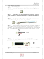
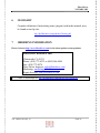
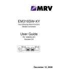
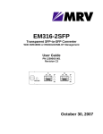
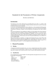
1
NC316BU-IDC Single-Slot Chassis With Internal 48VDC Power Supply User’s Guide Fiber Driver NC316BU-1DC Registration Card Your name: Mr./Ms___________________________________________ Organization: ________________________Dept. __________________ Your title at organization:______________________________________ Telephone: ___________________________ Fax:__________________ Organization's full address:____________________________________ __________________________________________________________ Country:___________________________________________________ Date of purchase (Month/Day/Year):_____________________________ Serial number: Product was purchased from: Reseller's name:____________________________________________ Telephone:___ __________________ Fax:_______________________ Reseller's full address___________________________________________________ ___________________________________________________ Answers to the following questions help us to support your product: 1. Where and how will the product primarily be used? Home Office Travel Company Business Home Business Personal Use 2. How many employees work at installation site? 1 employee 2-9 10-49 50-99 100-499 500-999 1000+ 3. What network medium/media does your organization use ? Fiber-optics Thick coax Ethernet Thin coax Ethernet 10BASE-T UTP/STP 100BASE-TX 100BASE-T4 100VGAnyLAN Others_________________ 4. What category best describes your company? Aerospace Engineering Education Finance Hospital Legal Insurance/Real Estate Manufacturing Retail/Chain store/Wholesale Government Transportation/Utilities/Communication VAR System house/company Other________________________________ 5. Would you recommend your Fiber Driver product to a friend? Yes No Don't know yet P/N: 1200003-002, REV_D PAGE 2 Fiber Driver NC316BU-1DC Single-Slot Chassis With Internal 48VDC Power Supply User’s Guide P/N: 1200003-002, REV_D PAGE 3 Fiber Driver NC316BU-1DC TABLE OF CONTENTS 1 INTRODUCTION 2 HARDWARE INSTALLATION 3 TROUBLESHOOTING 4 TECHNICAL SPECIFICATIONS 5 CONTACT INFORMATION 6 GLOSSARY 7 ORDERING INFORMATION P/N: 1200003-002, REV_D PAGE 4 Fiber Driver NC316BU-1DC 1 INTRODUCTION About this Manual This manual is a guide to the installation and operation of the NC316BU-1DC Fiber driver single slot chassis. Product description describes the product, its functions, features, protocol supported, minimum requirements, and typical applications. Installation guides you through the setup of the NC316BU-1DC to your network. Customer support provides information on return policy and customer support information. Glossary provides definition to terms used in this manual. Before unpacking please refer to section 2 (Hardware Installation) Product Description This is a 6.25” x 1.5” x 8”chassis designed to power any single module Fiber Driver (EM316 Family). It comes with a –48VDC power supply. The chassis can be used with a wall-mounting bracket, if needed. Features • • • Chassis can be used to power all EM316 single module Uses a -48VDC power supply Can be Desktop or Wall Mount *For dB budget see: ftp://ftp.fiberdriver.com/pub/doc/spec/fiberdriver P/N: 1200003-002, REV_D PAGE 5 Fiber Driver NC316BU-1DC Typical Applications NC316BU-1DC (Shown with an installed Fiber Driver module) P/N: 1200003-002, REV_D PAGE 6 Fiber Driver NC316BU-1DC 2 HARDWARE INSTALLATION PREPARATION STEP 1 Follow all Safety Regulations 1 Eliminate static electricity in the workplace by grounding operators, equipment, and devices (components and computer boards). Grounding prevents static charge buildup and electrostatic potential differences. Transporting products in special electrostatic shielding packages avert electrical field damage. 2 An effective workplace should be outfitted with the following items: a) ESD protective clothing/smocks: Street clothing must not come in contact with components or computer boards since the various materials in clothing can generate high static charges. ESD protective smocks, manufactured with conductive fibers, are recommended. b) Electrostatic shielding containers or totes: These containers (bags, boxes, etc.) are made of specially formulated materials, which protect sensitive devices during transport and storage. c) Antistatic or dissipative carriers: These provide ESD protection during component movement in the manufacturing process. It must be noted that antistatic materials alone will not provide complete protection. They must be used in conjunction with other methods such as totes or electrostatic shielding bags. d) Dissipative tablemat: The mat should provide a controlled discharge of static voltages and must be grounded. The surface resistance is designed such that sliding a computer board or component across its surface will not generate more than 100 V. e) Personal grounding: A wrist strap or ESD cuff is kept in constant contact with bare skin and has a cable for attaching it to the ESD ground. The purpose of the wrist strap is to drain off the operator’s static charge. The wrist strap cord has a current-limiting resistor for personnel safety. Wrist straps must be tested frequently to ensure that they are undamaged and operating correctly. When a wrist strap is impractical, special heel straps or shoes can be used. These items are effective only when used in conjunction with a dissipative floor. P/N: 1200003-002, REV_D PAGE 7 Fiber Driver NC316BU-1DC f) STEP 2 ESD protective floor or mat: The mat must be grounded through a currentlimiting resistor. The floor or mat dissipates the static charge of personnel approaching the workbench. Special conductive tile or floor treatment can be used when mats are not practical or cause a safety hazard. Chairs should be conductive or grounded with a drag chain to the flooring. Determine the best location for the chassis. Affix the chassis to a 19” or 23” rack using the enclosed rack mount ears, or place the unit on a secure, flat surface. Ensure that the unit is within reach of the necessary connections (i.e. power outlet, Ethernet connections, and, if the chassis will be monitored via serial port, and either a PC, UNIX workstation, or modem). STEP 3 Make sure there is enough space to pull and connect both the electrical and optical cables without stressing them beyond the manufacturer’s limitation (bend radius minimum). STEP 4 The ambient temperature within the rack may be greater than the room ambient temperature. Installation should be such that the amount of airflow required for safe operation is not compromised. The maximum temperature for the equipment in this environment is 50oC. Consideration should be given to the maximum rated ambient temperature. STEP 5 STEP 6 Installation should be such that a hazardous stability condition is not achieved due to uneven loading. STEP 7 Check nameplate ratings to assure there is no overloading of supply circuits that could have an effect on over-current protection and supply wiring. STEP 8 When installing 48VDC rated equipment, it must be installed only per the following conditions: a) Connect the equipment to a 48VDC supply source that is electrically isolated from the alternating current source. The 48VDC source is said to be reliably connected to ground or connected to a 48VDC SELV source. b) To be installed only in restricted access areas (dedicated equipment rooms, equipment closets or the like) in accordance wit articles 110-16, 110-17, and 11018 of the National Electrical Code, ANSI/NFPA 70. c) Input wiring to terminal block must be routed and secured in such a manner that is protected from damage and stress. Do not route wiring past sharp edges or moving parts. P/N: 1200003-002, REV_D PAGE 8 Fiber Driver NC316BU-1DC d) A readily accessible disconnect device, with a 3mm minimum contact gap, shall be incorporated in the fixed wiring. STEP 9 Plug in the chassis Connect the power cord (s) to the chassis and an outlet. Turn the power switch (es) to ON position. The wide-ranging power supply adjusts to any outlet. STEP 10 Unpacking the unit Verify that no visible damage has been caused to the outer box. Remove all material from the packing box and confirm receipt of the following: Fiber Driver module unit User’s manual (this manual in printed format or on a CD) In the unlikely event that anything is missing, contact your authorized dealer or representative. If it becomes necessary to return the unit, repackage the unit in its original box. P/N: 1200003-002, REV_D PAGE 9 Fiber Driver NC316BU-1DC UNIT INSTALLATION STEP 1 Remove the Wago connector (shown below) which is plugged into the front of the unit. STEP 2 Prepare the 18 AWG wires (minimum gage wire required) you’re your 48VDC power source by stripping back approximately ¼” of insulation and exposing the bare wire. STEP 3 You will need a small screwdriver to wedge into the connector above the wire in order to open the pathway for the wire. See pictures below. STEP 4 Notice that the Wago connector is keyed. In the picture below install the red wire (+), chassis ground (center wire) and black wire (-), as shown. Insert a screwdriver as shown above, in the top rectangular holes and press upward then insert the wire into the round hole. Remove the screwdriver and tug on the wire to maker sure the connection is secured. Black Ground Red STEP 5 Now insert the plug into the front of the NC316BU-1DC in the receptacle provided. See picture below. Plug here STEP 6 Turn on your 48VDC power source when you are ready to use the NC316BU- 1DC. P/N: 1200003-002, REV_D PAGE 10 Fiber Driver NC316BU-1DC 3 TROUBLESHOOTING The Fiber Driver series are highly reliable units. If there are any operating problems, the fault probably lies in some other aspect of the configuration. However, if after following the troubleshooting steps below (in order), you find that the unit is still not functioning correctly, please contact your local MRV representative. Ensure that DC power is coming from the outlet. Please follow all safety precautions when doing this step. Install a functioning EM316 Fiber driver module and verify if the LED indicators of the module illuminates. If there are no lights coming from the LED indicators of the module, check for any loose connections, and verify all cable connections. If replacing the cable or reconnecting any loose connections, did not solve the problem, the unit power supply may be faulty, and the unit must be returned or replaced. Remove the module from the unit. Turn off your 48VDC power source. P/N: 1200003-002, REV_D PAGE 11 Fiber Driver NC316BU-1DC 4 TECHNICAL SPECIFICATIONS Electrical Input: 36-75VDC, Fuse= 0.5ADC Output: 5VDC, 2A Max Operating Temperature Range 0°C - +50 °C (32°F – 122°F) Storage temp -10°C - +60°C (28°F – 140°F) Relative Humidity 85% maximum non-condensing Emissions & Safety Compliance FCC Part 15, Sub. J, Class A ETL (UL-1950), TUV/VDE, cUL Physical Dimensions 1.5” high x 6.25” wide x 8” deep (3.81cm x 15.88cm x 20.32cm) Weight 3.5 lb (1.575 kg) Color Black P/N: 1200003-002, REV_D PAGE 12 Fiber Driver NC316BU-1DC 5 CUSTOMER SUPPORT Contact Information If you have any questions, please do not hesitate to contact us at: Americas Support MRV (East Coast USA) 295 Foster Street Littleton, MA 01460-2016 Tech Support: (800) 338-5316 Tech Support: (800) 952-4700 E-mail: [email protected] Fax: (978) 952-4880 URL: http://www.fiberdriver.com MRV (West Coast USA) 20415 Nordhoff St. Chatsworth, CA 91311 Tel. (800) 338-5316 Tel. (818) 773-0900 International Support Europe – Asia – Africa Industrial Zone P.O Box 614 Yokneam, 20682 Israel Tel: 972-4-993-6200 Fax: 972-4-989-2743 Email: [email protected] International Support: [email protected] International Field Offices UK Tel: 011-44-20-8564-0562 South Africa Tel: 011-27-11-664-6963 Israel Tel: 972-4-9936221 Australia & New Zealand Email: [email protected] Asia (excluding China) Email: [email protected] Benelux Hof van den Houte 77 4873 AZ Etten Leur The Netherlands Tel: (31) 76-508-3525 Fax: (31) 76-508-3535 Email: [email protected] France 11 Avenue de l'Isle St. Martin 92737 Nanterre Cedex France Tel: (33) 01 - 47 84 78 66 Fax: (33) 01 - 47 84 78 67 Email: [email protected] Germany Business Park Moerfelden Waldeckerstrasse 13 64546 Moerfelden-Walldorf Germany Tel: (49) 6105/207-0 Fax: (49) 6105/207-100 Email: [email protected] Italy Via Carlo Borromeo, 8 20059 Vimercate (MI) Italy Tel: (39) 039-661-2908 Fax: (39) 039-661-2943 Email: [email protected] Latin America Av. Alicia Moreau de Just 1050 - P.2 Buenos Aires 1107, Capital Federal Argentina Tel/Fax: (541) 14 345 6456 Email: [email protected] Russia Trubnaya str., 12 Moscow 103045 Russia Tel: (007) 095-787-2783 Fax: (007) 095-787-2759 Email: [email protected] Scandinavia Email: [email protected] UK 2 Manor Court, High Street Harmondsworth, Middlessex UB7 OAQ United Kingdom Tel: (44) 0208 - 564 0564 Fax: (44) 0208 - 564 0501 Email: [email protected] China COFCO PLAZA, room B1020 Tower B, 8 Jianguomennei Ave. Beijing 100005 China Tel: (86) 10-652-77-539 Fax: (86) 10-652-69-921 Email: [email protected] Manual Information: The most recent version of this manual may be found on our ftp site: ftp://ftp.fiberdriver.com/pub/doc/manuals/ P/N: 1200003-002, REV_D PAGE 13 Fiber Driver NC316BU-1DC 6 GLOSSARY Complete definition of networking terms (jargon) used in this manual, may be found on our ftp site: ftp://ftp.fiberdriver.com/pub/doc/Glossary.pdf 7 ORDERING INFORMATION Please visit us at http://www.fiberdriver.com for the latest updates on our products. Fiber Driver Division of MRV Chatsworth, CA 91311 Phone: (818) 772-6235 or (800) 966-4444 Fax: (818) 772-0576 Fiber Driver Inquiries: [email protected] Marketing: [email protected] Repair Services: [email protected] *Note: For dB budget see: ftp://ftp.fiberdriver.com/pub/doc/spec/fiberdriver P/N: 1200003-002, REV_D PAGE 14 Fiber Driver NC316BU-1DC This Page is Intentionally Left Blank P/N: 1200003-002, REV_D PAGE 15 Fiber Driver NC316BU-1DC This Page is Intentionally Left Blank P/N: 1200003-002, REV_D PAGE 16 Fiber Driver NC316BU-1DC This Page is Intentionally Left Blank P/N: 1200003-002, REV_D PAGE 17 Fiber Driver NC316BU-1DC This Page is Intentionally Left Blank P/N: 1200003-002, REV_D PAGE 18 P/N: 1200003-002, REV_D ------------------------------------------------ ------------------------------------------------ ------------------------------------------------ 8928 Fullbright Avenue Chatsworth, California 91311 U.S.A. Place Stamp Here Fiber Driver NC316BU-1DC PAGE 19