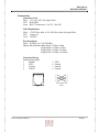
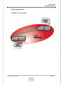
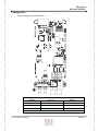
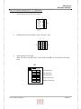
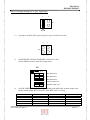
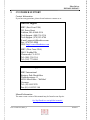
1
EM316T1 EM316E1 Fiber Driver Modem User’s Guide Fiber Driver EM316E1/EM316T1 Registration Card Your name: Mr./Ms___________________________________________ Organization: ________________________Dept. __________________ Your title at organization:______________________________________ Telephone: ___________________________ Fax:__________________ Organization's full address:____________________________________ __________________________________________________________ Country:___________________________________________________ Date of purchase (Month/Day/Year):_____________________________ Serial number: Product was purchased from: Reseller's name:____________________________________________ Telephone:___ __________________ Fax:_______________________ Reseller's full address___________________________________________________ ___________________________________________________ Answers to the following questions help us to support your product: 1. Where and how will the product primarily be used? Home Office Travel Company Business Home Business Personal Use 2. How many employees work at installation site? 1 employee 2-9 10-49 50-99 100-499 500-999 1000+ 3. What network medium/media does your organization use ? Fiber-optics Thick coax Ethernet Thin coax Ethernet 10BASE-T UTP/STP 100BASE-TX 100BASE-T4 100VGAnyLAN Others_________________ 4. What category best describes your company? Aerospace Engineering Education Finance Hospital Legal Insurance/Real Estate Manufacturing Retail/Chain store/Wholesale Government Transportation/Utilities/Communication VAR System house/company Other________________________________ 5. Would you recommend your Fiber Driver product to a friend? Yes No Don't know yet P/N: 1218003-001, REV_O PAGE 2 Fiber Driver EM316E1/EM316T1 EM316E1 EM316T1 Fiber Driver Modem User’s Guide P/N: 1218003-001, REV_O PAGE 3 Fiber Driver EM316E1/EM316T1 TABLE OF CONTENTS 1 INTRODUCTION 2 HARDWARE INSTALLATION 3 TROUBLESHOOTING 4 TECHNICAL SPECIFICATIONS 5 CONTACT INFORMATION 6 GLOSSARY 7 ORDERING INFORMATION P/N: 1218003-001, REV_O PAGE 4 Fiber Driver EM316E1/EM316T1 1 INTRODUCTION About this Manual Before unpacking please refer to section 2 (Hardware Installation) This manual is a guide to the installation and operation of the EM316E1/T1 Fiber Modem. Product description describes the product, its functions, features, protocol supported, minimum requirements, and typical applications. Installation guides you through the setup of the EM316E1/T1 to your network. Customer support provides information on return policy and customer support information. Glossary provides definition to terms used in this manual. Product Description The EM316T1 and the EM316E1 modules of the Fiber Driver Family are Fiber Modems designed to extend the distance and transmission reliability of T1 (1.544Mbps) or E1 (2.048Mbps) traffic. These units convert the electrical signals to optical signals and transmit them over distances of up to 4km on multimode fiber, or distances of up to 100km on singlemode fiber. The EM316T1 and EM316E1 are transparent to the framing format, and support AMI or B8ZS (T1) and HDB3 (E1) line codes respectively. They include an internal elastic buffer to remove jitter from transmit data. Six LED indicators help monitoring and trouble-shooting, and a management agent is incorporated on the module to enable remote in-band and out-of-band control and management in conjunction with the Fiber Driver SNMP management card. The EM316E1/T1 single fiber modules use unique technology that provides the ability to combine TX and RX signals onto a single fiber strand. This effectively doubles the available fiber in a network and eliminates the need for additional fiber connections. An identical unit is required on the other end, using either standard APC (Angled PC) patch cords finish or a 3M VAR APC finish. The standard APC finish provides a <-60dB back reflection, whereas the 3M VAR exceeds –70dB. Both APC finishes are polished to an 8o angle and minimize back reflection by forcing the reflected rays into the cladding. The Fiber Driver family provides conversion solutions with greater distances and better manageability than any other products on the market. Multimode to Singlemode fiber conversion modules offers link distances from 0 km to 100 km. P/N: 1218003-001, REV_O PAGE 5 Fiber Driver EM316E1/EM316T1 Features • • • • • • • • • Modules can be Inserted / Removed without powering off the chassis Extensive Network Management Support when used with EM316NM Provide Fiber Link for T1(ANSI T1.403) or E1 (G.703) Applications Built-in Elastic Buffer to Remove Jitter LED Indicators to help Trouble-Shooting Support AMI/B8ZS/HDB3 Line Codes Up to 100km Transmission on Singlemode or 4km on Multimode Fiber AC 110-220 volts or -48 DC power Supports Local & Remote Loopback Test *For dB budget see: ftp://ftp.fiberdriver.com/pub/doc/spec/fiberdriver Requirements for Managed Module EM316NM Management Firmware version 3.43 or later For firmware released version go to: ftp://ftp.fiberdriver.com/pub/software/em316nm For firmware beta version go to: ftp://ftp.fiberdriver.com/pub/software/beta/em316nm MegaVision Network Management version 1.17 or later P/N: 1218003-001, REV_O PAGE 6 Fiber Driver EM316E1/EM316T1 Connectivity Connectors Used Fiber: ST, or SC-APC (for single fiber) UTP: RJ48-MDI Coax: BNC (2 connectors: 1 for TX, 1 for RX) Cable Requirement Fiber: ST-ST fiber cable, or SC-APC fiber cable (for single fiber) UTP: Category 5 Coax: RG58/U Port Description Input: E1 (BNC) or T1 (UTP-RJ48) Output: Fiber Modem, Multi-Mode: 1310nm, 0-2km Single Mode: 1310nm, 0-25km Single Mode: 1310nm, 25-50km Single Mode: 1550nm, 50-100km Connector Pin-out Female RJ-48 (MDI) 1 RRING 2 RTIP 3 Unused 4 TRING 1 5 6 7 8 TTIP Unused Unused Unused 8 1 1 2 2 4 4 5 5 Crossed Cable Pin-Out RJ48 Connector Pin-Out Figure 2 Figure 1 P/N: 1218003-001, REV_O PAGE 7 Fiber Driver EM316E1/EM316T1 Display Information (LED Definition) • PWR/NMS: • • • TX: RX: AIS: • LOS: • SD: P/N: 1218003-001, REV_O illuminates when unit is powered (green color), flashes (green color) when remote or local loop back is enabled by management. The remote loop back feature provides a quick check of the basic functionality of both modems and both fiber optic cable paths. It will send a signal that causes the remote EM316E1/T1 fiber modem to loop its received data and send it back out as its transmitted optical signal, this will cause the loop back indicator to flash (green color) flashes when Fiber TX is active, (OFF through all zeros transmission) flashes when Fiber RX is active Alarm Indication Signal illuminates when unframed all-ones condition is detected, using the detection criteria of less than 9 zeroes out of 8129 bit periods. Loss of Signal illuminates when 175 consecutive zeroes have been received. LOS return low when the ones density reaches 12.5% (based upon 175 bit periods starting with a one & containing less than 100 consecutive zeroes). illuminates when fiber signal is detected PAGE 8 Fiber Driver EM316E1/EM316T1 Typical Applications EM316E1/T1 (Fiber Modem) P/N: 1218003-001, REV_O PAGE 9 Fiber Driver EM316E1/EM316T1 Configuration Jumper Settings: (Factory Default) DO NOT CHANGE THE JUMPER SETTINGS BELOW JUMPER SETTINGS JP2 OPEN Factory Use Only JP9 OPEN Factory Use Only W1 OPEN Factory Use Only Note: P/N: 1218003-001, REV_O RESULTS * Jumper settings with asterisk (*) are factory default PAGE 10 Fiber Driver EM316E1/EM316T1 EM316E1 Jumper Settings for E1 120Ω Application : 1) Install jumpers between JP3 pins 1 and 2, 2 4 JP3 1 2) 3 No jumpers on JP4 and JP5 open, (all pins are open) JP4 JP5 1 3) 1 Set all switches on S1 to ON. (BIT2=ON, BIT1=ON, BIT0=ON), for E1 and choose HDB3 as encoder & decoder testing mode S1 O N 1 2 LINE LENGTH BIT1 3 LINE LENGTH BIT2 4 RECEIVE CODE TYPE 5 P/N: 1218003-001, REV_O LINE LENGTH BIT0 TRANSMIT CODE TYPE PAGE 11 Fiber Driver EM316E1/EM316T1 EM316E1 Jumper Settings for E1 75Ω Application : 1) Install jumpers between JP3 pins 3 and 4, 2 4 JP3 1 2) 3 Install jumpers between JP4 pins 1 and 2, JP5 pins 1 and 2 2 2 JP5 JP4 1 3) 1 Set all switches on S1 to ON. (BIT2=ON, BIT1=ON, BIT0=ON), for E1 and choose HDB3 as encoder & decoder testing mode S1 O N 1 2 LINE LENGTH BIT1 3 LINE LENGTH BIT2 4 RECEIVE CODE TYPE 5 P/N: 1218003-001, REV_O LINE LENGTH BIT0 TRANSMIT CODE TYPE PAGE 12 Fiber Driver EM316E1/EM316T1 EM316T1 Jumper Settings for T1 100Ω Application : 1.) Install jumpers between JP3 pins 1 and 2, 2 4 JP3 1 2.) 3 No jumpers on JP4 and JP5 open, (all pins are open, no headers, not used) 2 2 JP5 JP4 1 3) 1 Set RECEIVED CODE and TRANSMIT CODE on S1 to ON. (Choose B8ZS as encoder & decoder testing mode) S1 O N 1 2 LINE LENGTH BIT1 3 LINE LENGTH BIT2 4 RECEIVE CODE TYPE 5 4) LINE LENGTH BIT0 TRANSMIT CODE TYPE Set LINE LENGTH (BIT0, BIT1, BIT2) according to the table below to match copper cable length (default settings: BIT2=ON, BIT1=OFF, BIT0=OFF, 0-133 feet) BIT2 ON OFF OFF OFF OFF P/N: 1218003-001, REV_O BIT1 OFF ON ON OFF OFF BIT0 OFF ON OFF ON OFF Copper cable length 0 - 133 feet 133 - 266 feet 266 - 399 feet 399 - 533 feet 533 - 655 feet PAGE 13 Fiber Driver EM316E1/EM316T1 Theory of Operation Data encoding used on the EM316E1/T1 Fiber Modem consists of converting the incoming AMI B8ZS or HDB3 to a format suitable for fiber optic communication. A proprietary coding scheme is used which combines the input clock and data into a composite signal that is then transmitted over the fiber. At the receiver, this composite signal is then separated back into their respective formats. This coding technique provides a composite data pulse for each incoming data bit. This assures that the original timing information for each bit is transferred and can be recovered. Decoding long zero runs in the AMI code does not rely on timing interpolation between the transfer of AMI ones. Each incoming logic one data bit produces a pulse having a fixed width of approximately 2/3 the bit rate and a logic zero data bit produces a pulse width of approximately 1/3 the bit rate. The leading edge of all data bits is synchronous to the input and output data clock. Since the composite fiber data stream utilizes this pulse width scheme, no synchronizing headers are required which results in faster recovery from loss of signal data errors and guaranteeing true data and timing transparency. P/N: 1218003-001, REV_O PAGE 14 Fiber Driver EM316E1/EM316T1 2 HARDWARE INSTALLATION PREPARATION STEP 1 Follow all Safety Regulations 1 Eliminate static electricity in the workplace by grounding operators, equipment, and devices (components and computer boards). Grounding prevents static charge buildup and electrostatic potential differences. Transporting products in special electrostatic shielding packages avert electrical field damage. 2 An effective workplace should be outfitted with the following items: a) ESD protective clothing/smocks: Street clothing must not come in contact with components or computer boards since the various materials in clothing can generate high static charges. ESD protective smocks, manufactured with conductive fibers, are recommended. b) Electrostatic shielding containers or totes: These containers (bags, boxes, etc.) are made of specially formulated materials, which protect sensitive devices during transport and storage. c) Antistatic or dissipative carriers: These provide ESD protection during component movement in the manufacturing process. It must be noted that antistatic materials alone will not provide complete protection. They must be used in conjunction with other methods such as totes or electrostatic shielding bags. d) Dissipative tablemat: The mat should provide a controlled discharge of static voltages and must be grounded. The surface resistance is designed such that sliding a computer board or component across its surface will not generate more than 100 V. e) Personal grounding: A wrist strap or ESD cuff is kept in constant contact with bare skin and has a cable for attaching it to the ESD ground. The purpose of the wrist strap is to drain off the operator’s static charge. The wrist strap cord has a current-limiting resistor for personnel safety. Wrist straps must be tested frequently to ensure that they are undamaged and operating correctly. When a wrist strap is impractical, special heel straps or shoes can be used. These items are effective only when used in conjunction with a dissipative floor. P/N: 1218003-001, REV_O PAGE 15 Fiber Driver EM316E1/EM316T1 f) STEP 2 ESD protective floor or mat: The mat must be grounded through a currentlimiting resistor. The floor or mat dissipates the static charge of personnel approaching the workbench. Special conductive tile or floor treatment can be used when mats are not practical or cause a safety hazard. Chairs should be conductive or grounded with a drag chain to the flooring. Determine the best location for the chassis. Affix the chassis to a 19” or 23” rack using the enclosed rack mount ears, or place the unit on a secure, flat surface. Ensure that the unit is within reach of the necessary connections (i.e. power outlet, Ethernet connections, and, if the chassis will be monitored via serial port, and either a PC, UNIX workstation, or modem). STEP 3 Make sure there is enough space to pull and connect both the electrical and optical cables without stressing them beyond the manufacturer’s limitation (bend radius minimum). STEP 4 Plug in the chassis Connect the power cord (s) to the chassis and an outlet. Turn the power switch (es) to ON position. The wide-ranging power supply adjusts to any outlet. STEP 5 Unpacking the unit Verify that no visible damage has been caused to the outer box. Remove all material from the packing box and confirm receipt of the following: Fiber Driver module unit User’s manual (this manual in printed format or on a CD) In the unlikely event that anything is missing, contact your authorized dealer or representative. If it becomes necessary to return the unit, repackage the unit in its original box. P/N: 1218003-001, REV_O PAGE 16 Fiber Driver EM316E1/EM316T1 UNIT INSTALLATION STEP 1 Remove required amount of blank panels from the NC316BU-xx. NOTE: Per FCC regulations, either a panel or a module should always cover chassis slots. FIGURE 1.1 Take out the required amount of blank panels. STEP 2 Align the edges of the EM316 module to the rail inside the chassis, see pictures below. FIGURE 1.2 Align the edges of the EM316 to the rail inside the chassis and then insert the unit. P/N: 1218003-001, REV_O PAGE 17 Fiber Driver EM316E1/EM316T1 STEP 3 Insert the module into the NC316BU-xx unit NOTE: To avoid damaging any components on the module, handle it by the edges, using your thumb to push it securely inside the chassis. Do not use excessive force, but make sure the module is fully inserted in the chassis. When the module is correctly inserted, the PWR LED should illuminate. STEP 4 Secure the module to the unit, using the screws on the front panel. FIGURE 1.3 When the module is correctly inserted, the PWR LED should illuminate. WARNING! Fiber optic equipment can emit laser or infrared light that might injure your eyes. Never look into an optical fiber or connector port. Always assume that fiber optic cables are connected to a light source. P/N: 1218003-001, REV_O PAGE 18 Fiber Driver EM316E1/EM316T1 3 TROUBLESHOOTING The Fiber Driver series are highly reliable units. If there are any operating problems, the fault probably lies in some other aspect of the configuration. However, if after following the troubleshooting steps below (in order), you find that the unit is still not functioning correctly, please contact your local representative. Review all link LEDs to ensure that those ports you believe should be functioning are properly attached to a cable. Verify the correct fiber optic cables are being used, i.e. multi-mode or single mode. Review all link LEDs to ensure that those ports you believe should be functioning are properly configured. If the suspect ports are not configured properly, re-configure the port through SNMP management or the Administrative Interface. Ensure that the equipment attached to this module is configured properly. Verify that the output power of the fiber optic port(s) is within manufacturer’s specification for output power, for more information please see the link below: ftp://ftp.fiberdriver.com/pub/doc/spec/fiberdriver Verify that the dB loss of the Fiber cable you are connecting to is within the dB budget for this module, for more information please see the link below: ftp://ftp.fiberdriver.com/pub/doc/spec/fiberdriver P/N: 1218003-001, REV_O PAGE 19 Fiber Driver EM316E1/EM316T1 4 TECHNICAL SPECIFICATIONS Electrical 5VDC @ 2 Amps Max Hot Swappable Operating Temperature Range 0°C - +50 °C (32°F – 122°F) Storage temp -10°C - +60°C (14°F – 140°F) Relative Humidity 85% maximum non-condensing Emissions Compliance FCC Part 15, Subpart B, 1999 Class A CE Mark EN 50081-1: 1992 EN 50082-1: 1997 EN 55024: 1998 EN 55022: 1998 AS/NZS 3548: 1995 Physical Dimensions 1” high x 3” wide x 7” deep (2.54cm x 7.62cm x 12.78cm) Weight 9.6 oz (0.36 kg) Color Black P/N: 1218003-001, REV_O PAGE 20 Fiber Driver EM316E1/EM316T1 5 CUSTOMER SUPPORT Contact Information If you have any questions, please do not hesitate to contact us at: Americas Support MRV (East Coast USA) 295 Foster Street Littleton, MA 01460-2016 Tech Support: (800) 338-5316 Tech Support: (978) 952-4700 E-mail: [email protected] Fax: (978) 952-4880 URL: http://www.fiberdriver.com MRV (West Coast USA) 20415 Nordhoff St. Chatsworth, CA 91311 Tel. (800) 338-5316 Tel. (818) 773-0900 International Support MRV International Business Park Moerfelden Waldeckerstrasse 13 64546 Moerfelden – Walldorf Germany Tel. (49) 6105/2070 Fax (49) 6105/207-100 Manual Information The most recent version of this manual may be found on our ftp site: ftp://ftp.fiberdriver.com/pub/doc/manuals/ P/N: 1218003-001, REV_O PAGE 21 Fiber Driver EM316E1/EM316T1 5 GLOSSARY Complete definition of networking terms (jargon) used in this manual, may be found on our ftp site: ftp://ftp.fiberdriver.com/pub/doc/Glossary.pdf 6 ORDERING INFORMATION Please visit us at http://www.fiberdriver.com for the latest updates on our products. Fiber Driver Division of MRV Chatsworth, CA 91311 Phone: (818) 772-6235 or (800) 966-4444 Fax: (818) 772-0576 Fiber Driver Inquiries: [email protected] Marketing: [email protected] Repair Services: [email protected] *Note: For dB budget see: ftp://ftp.fiberdriver.com/pub/doc/spec/fiberdriver P/N: 1218003-001, REV_O PAGE 22 P/N: 1218003-001, REV_O ------------------------------------------------ ------------------------------------------------ ------------------------------------------------ 8928 Fullbright Avenue Chatsworth, California 91311 U.S.A. Place Stamp Here Fiber Driver EM316E1/EM316T1 PAGE 23