1
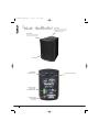
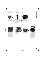
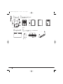
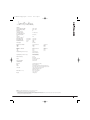
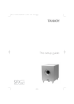
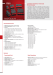
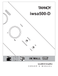
Di5a Manual AW.qxp:Layout 1
25/5/07
10:45
Page 1
THE
USER MANUAL
Di5a Manual AW.qxp:Layout 1
25/5/07
10:45
Page 2
3 INTRODUCTION
3 SAFETY INSTRUCTIONS
4 PRODUCT IDENTIFICATION
5 STANDARD AND OPTIONAL ACCESSORIES
6-7 INSTALLATION GUIDELINES
6
Installation using supplied yoke bracket
7
Installation using supplied yoke bracket with optional pole-mount adaptor
8 PRODUCT DIMENSIONS
8 HARDWARE DIMENSIONS
9 TECHNICAL SPECIFICATIONS
10 WARRANTY STATEMENT
11 DECLARATION OF CONFORMITY
2
Di5a Manual AW.qxp:Layout 1
25/5/07
10:45
Page 3
THE
For applications requiring extended low frequency enhancement, a range of Tannoy sub-bass systems are available and can
be used in conjunction with the Di5a.
1.
2.
3.
4.
5.
6.
7.
8.
9.
10.
11.
12.
13.
14.
15.
16.
17.
18.
19.
20.
21.
USER MANUAL
Designed for a wide variety of sound reinforcement applications the Tannoy Di5a is an ultra compact active loudspeaker
system capable of delivering high sound pressure levels with extremely low distortion, resulting in outstanding clarity,
definition and detail. A truly universal solution, the Di5a offers outstanding durability and resistance to scuffs and knocks.
Available in black or white the Di5a will effectively blend into most backgrounds. Utilisation of the point source loudspeaker
allows the Di5a to be mounted on a wall or ceiling in either horizontal or vertical orientations without affecting its performance.
A range of hardware options ensures simple and effective installation.
Read these instructions.
Keep these instructions.
Heed all warnings.
Follow all instructions.
The user is responsible for fixing the hardware to the surface to ensure safe operation. The fixings must support the
weight of the product – please consult the manual’s specification page for the appropriate weights. Please consult the
relevant construction codes in your region for further information on suitable hardware fixing methods.
Some regional construction codes require the use of a secondary method of securing loudspeakers to surfaces to
provide security of a back-up support. A secondary support line should be attached from the safety loop on the rear of the
product to a source point on the wall. Please consult the relevant construction codes in your region.
Tannoy will not be held accountable for any damage caused by incorrect installation.
Clean only with dry cloth.
Do not block any ventilation openings. Install in accordance with instructions.
Do not install near any heat sources such as radiators, heat registers, stoves, or other apparatus (including amplifiers)
that produce heat.
Only use attachments/accessories specified by the manufacturer.
Protect the power cord from being walked on or pinched particularly at plugs, convenience receptacles, and the
point where they exit from the apparatus.
Only use attachments/accessories specified by the manufacturer.
Refer all servicing to qualified service personnel. Servicing is required when the apparatus has been
damaged in any way, such as power-supply cord or plug is damaged, liquid has been spilled or objects
have fallen into the apparatus, the apparatus has been exposed to rain or moisture, does not operate
normally, or has been dropped.
Unplug this apparatus during lightning storms or when unused for long periods of time.
Refer all servicing to qualified service personnel. Servicing is required when the apparatus has been damaged in any
way, such as power-supply cord or plug is damaged, liquid has been spilled or objects have fallen into the apparatus,
the apparatus has been exposed to rain or moisture, does not operate normally, or has been dropped.
Do not expose this apparatus to dripping or splashing and ensure that no objects
filled with liquids, such as vases, are placed on the apparatus.
To completely disconnect this apparatus from the AC Mains, disconnect the
power supply cord plug from the AC receptacle.
The mains plug of the power supply cord shall remain readily operable.
Do not expose batteries to excessive heat such as sunshine, fire or the like.
This apparatus is a Class 1 device construction and that is shall be connected to a mains socket outlet with a protective
earthing connection.
The lightning flash with arrowhead symbol within an
equilateral triangle, is intended to alert the user to the
presence of uninsulated "dangerous voltage " within the
product's enclosure that may be of sufficient magnitude
to constitute a risk of electric shock to persons.
The exclamation point within an equilateral triangle is
intended to alert the user to the presence of important
operating and maintenance (servicing) instructions in the
literature accompanying the product.
WARNING: Failure to follow these safety
instructions could result in fire, electric shock, or
other injury or damage.
WARNING: To reduce the risk of fire or electric
shock, do not expose this apparatus to rain, liquids,
moisture, excessive heat, or naked flame.
WARNING: To prevent injury, this apparatus
must be securely attached to the floor / wall / pole
in accordance with the installation instructions.
3
Di5a Manual AW.qxp:Layout 1
25/5/07
10:45
Page 4
YOKE TRIM
Remove the yoke trims on the top
and bottom panels to access the
yoke bracket fixing point
GRILLE TRIM
Lift the grille trim back using the
tab to access the level control.
GRILLE
POWER INPUT
SOCKET (IEC TYPE)
POWER ON/ OFF SWITCH
LINE LEVEL AUDIO
INPUT/ OUTPUT
SOCKET (EURO TYPE)
LINE LEVEL AUDIO
INPUT SOCKET
(RCA TYPE)
4
Di5a Manual AW.qxp:Layout 1
25/5/07
10:45
Page 5
THE
GRILLE
USER MANUAL
GRILLE TRIM
YOKE BRACKET
(SUPPLIED WITH
FIXINGS)
POWER CORD
NOTE: The Di5a is supplied with a mains cord appropriate to your country. For UK and European
countries, please select the mains cord which suits your mains supply socket.
POLE MOUNT ADAPTOR
5
Di5a Manual AW.qxp:Layout 1
25/5/07
10:45
Page 6
USING SUPPLIED YOKE BRACKET
1. Fix the yoke bracket
to the surface using a
suitable fixing method.
2. Remove the yoke
trims from the product
to access the bracket
fixing points.
3. Connect the supplied
IEC power cord to the
Di5a. Note that the
Di5a is supplied with a
mains cord appropriate
to your country. For UK
and European
countries, please select
the mains cord which
suits your mains supply
socket.
4. Connect the
loudspeaker
appropriately using
either the RCA or
euro-type socket.
5. Adjust the level
control underneath the
grille trim.
6. Offer the speaker up
to the bracket and attach
it using a 5mm allen key
and supplied fixings.
The buffers that fit
between the speaker
and bracket should be
positioned as shown
above. Use the longer
hex-screws supplied
when mounting the
yoke bracket.
6
Di5a Manual AW.qxp:Layout 1
25/5/07
10:45
Page 7
THE
USING POLE MOUNT ADAPTOR
USER MANUAL
1. Use the supplied
fixings to fix the yoke
bracket to the pole
bracket adaptor.
2. Fix the pole mount
bracket adaptor to the
pole using the strapping
provided. The bracket
can be mounted in
portrait or landscape
orientations.
3. Remove the yoke
trims from the product
to access the bracket
fixing points.
4. Connect the supplied
IEC power cord to the
Di5a. Note that the Di5a
is supplied with a mains
cord appropriate to your
country. For UK and
European countries,
please select the mains
cord which suits your
mains supply socket.
5. Connect the
loudspeaker
appropriately using
either the RCA or
euro-type socket.
6. Adjust the level
control underneath the
grille trim.
7. Offer the speaker up
to the bracket and attach
it using a 5mm allen key
and supplied fixings.
The buffers that fit
between the speaker
and bracket should be
positioned as shown
above. Use the longer
hex-screws supplied
when mounting the
yoke bracket.
7
R165.0
R165.0
[R6.50"]
[R6.50"]
7∞ 7∞
Di5a Manual AW.qxp:Layout 1
25/5/07
10:45
Page 8
102.0
102.0
[4.02"]
[4.02"]
162.0
162.0
[6.38"]
[6.38"]
Di5a 155.0
155.0
R300.0
R300.0
[R11.81"]
[R11.81"]
[6.10"]
[6.10"]
240.7
240.7
[9.47"]
[9.47"]
R15.0
[R0.59"]
241.0
[9.49"]
85.0
[3.35"]
123.0
[4.84"]
6.0
[0.24"]
35.0
[1.38"]
54.0
[2.13"]
8
90.0
[3.54"]
?22.0
[?0.87"]
654321
654321
5” YOKE BRACKET
Di5a Manual AW.qxp:Layout 1
25/5/07
10:45
Page 9
THE
Di5a
SYSTEM
100Hz – 25kHz
90Hz – 30kHz
Dispersion
Degrees conical -6dB
90
Low Frequency Driver
Mineral loaded polypropylene
1x 110mm (4.50”)
High Frequency Driver
ICTTM
25mm (0.98”)
Crossover
Inductively Coupled ICTTM
7kHz
Directivity Factor (Q)
1kHz to 10kHz
Directivity Index (DI)
1kHz to 10kHz
6.6 averaged
Rated Maximum SPL (2)
Average
Peak
103dB
109dB
USER MANUAL
Frequency Response (-3dB) (1)
Frequency Range (-10dB) (1)
5.3 averaged
Power Output
30W RMS
Distortion 10% Full Power
250Hz
1kHz
10kHz
(4.25V) 2nd Harmonic
1.33%
0.62%
1.43%
3rd Harmonic
0.25%
0.16%
0.35%
Distortion 1% Full Power
250Hz
1kHz
10kHz
(1.34V) 2nd Harmonic
0.41%
0.23%
0.32%
3rd Harmonic
0.10%
0.07%
0.18%
Input Sensitivity (for maximum input)
775mV (balanced)
500mV (unbalanced)
Input Impedance (for maximum input)
11k Ohm (balanced)
7k Ohm (unbalanced)
Protection Circuitry
Thermal
Soft Limiting
Supply
100 - 240V AC, 50 – 60Hz
Fuse T1AL 250V
76VA maximum
Power Consumption
CONSTRUCTION
Enclosure
High impact polystyrene (HIPS)
Grille
Powder coated steel
Finish
Textured black or white paint with matching rubber trims
Factory fitted custom trim colours available to special order
Connectors
6 way euro-type input / output connector
Unbalanced RCA (phono) input
Mains inlet IEC type C13
Dimensions (H x W x D)
240.7 x 155.0 x 162.0mm
9.47 x 6.10 x 6.38”
2.40kg (5.3lbs)
Weight
Notes:
(1) Average over stated bandwidth. Measured at 1 metre on axis in an anechoic chamber
(2) Unweighted pink noise input, measured at 1 metre in an anechoic chamber
A full range of measurements, performance data, and EaseTM Data can be downloaded from www.tannoy.com
Tannoy operates a policy of continuous research and development. The introduction of new materials or manufacturing methods will always equal or exceed the published specifications,
which Tannoy reserves the right to alter without prior notice.
9
Di5a Manual AW.qxp:Layout 1
25/5/07
10:45
Page 10
No maintenance of the Di loudspeaker is necessary.
All of our products have been produced and tested with care and precision to give first-class service.
All passive components are guaranteed for a period of five years from the date of purchase from an authorised Tannoy dealer
subject to the absence or evidence of misuse, overload, or accidental damage.
All active and electronic components are guaranteed for a period of one year from the date of purchase from an authorised
Tannoy dealer subject to the absence of, or evidence of, misuse, overload or accidental damage.
If at any time during this warranty period the equipment proves to be defective for any reason other than accident, misuse,
neglect, unauthorised modification or fair wear and tear, we will repair any such manufacturing defect or, at our option, replace it
without charge for labour, parts or return carriage.
If you suspect a problem with a Tannoy product then, in the first instance, discuss it with your Tannoy dealer. If you require further
assistance then we ask that you deal directly with your local Tannoy distributor. If you cannot locate your distributor please contact
Customer Services, Tannoy Ltd at the address given below.
Customer Services, Tannoy Ltd., Rosehall Industrial Estate, Coatbridge, Strathclyde ML5 4TF, Scotland
Telephone:
Fax:
E-mail:
01236 420199
(National)
+44 1236 420199
(International)
01236 428230
(National)
+44 1236 428230
(International)
[email protected]
DO NOT SHIP ANY PRODUCT TO TANNOY WITHOUT PREVIOUS AUTHORISATION
Our policy commits us to incorporating improvements to our products through continuous research
and development. Please confirm current specifications for critical applications with your supplier.
10
Di5a Manual AW.qxp:Layout 1
25/5/07
10:45
Page 11
THE
Details of the Apparatus:
Associated Technical File:
Applicable Standards:
Signed:
Position:
Date:
USER MANUAL
The following apparatus is manufactured in China for Tannoy Ltd of Rosehall Industrial Estate, Coatbridge, Scotland, ML5 4TF
and conform(s) to the protection requirements of the European Electromagnetic Compatibility Standards and Directives
relevant to Domestic Electrical Equipment. The apparatus is designed and constructed such that electromagnetic
disturbances generated do not exceed levels allowing radio and telecommunications equipment and other apparatus to
operate as intended, and, the apparatus has an adequate level of intrinsic immunity to electromagnetic disturbance to enable
operation as specified and intended.
Tannoy Contractor Loudspeaker
Model Number: Di
EMCi6
EN 50081-1 Emission
EN 50082-1 Immunity
Director of Engineering (Professional)
9th May. 07
11
Di5a Manual AW.qxp:Layout 1
25/5/07
10:45
Page 12
REVISION DATE: 25 May ‘07
T: 00 44 (0) 1236 420199
T: 00 1 (519) 745 1158
T: 00 49 (180) 1111 881
T: 00 33 (0)1 7036 7473
E: [email protected]
E: [email protected]
E: [email protected]
E: [email protected]
Tannoy adopts a policy of continuous improvement and product specification is subject to change.
6481 0512
Tannoy United Kingdom
Tannoy North America
Tannoy Deutschland
Tannoy France