1
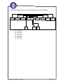
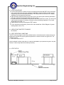
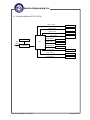
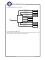
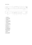
Neutron Engineering Inc.
Declaration
Neutron represents to the client that testing is done in accordance with standar d procedures as applicable
and that test instruments used has been calibrated with the standards traceable to National Measurement
Laboratory (NML) of R.O.C., or National Institute of Standards and Technology ( NIST) of U.S.A.
Neutron's reports apply only to the specific samples tested under conditions. It is manufacture ’s
responsibility to ensure that additional production units of this model are manufactured with the identical
electrical and mechanical components. Neutron shall have no liability for any declarations, inferences or
generalizations drawn by the client or others from Neutron issued reports.
Neutron’s reports must not be used by the client to claim product endorsement by the authorities or any
agency of the Government.
This report is the confidential property of the client. As a mutual protection to the clients, the public and
Neutron-self, extracts from the test report shall not be reproduced except in full with Neutron’s authorized
written approval.
Neutron’s laboratory quality assurance procedures are in compliance with the ISO Guide 17025
requirements, and accredited by the conformity assessment authorities listed in this test report.
Limitation
For the use of the authority's logo is limited unless the Test Standard(s)/Scope(s)/It em(s) mentioned in this
test report is (are) included in the conformity assessment authorities acceptance respective.
Report No.: NEI-SMA-1-1001C020
Page 2 of 32
Neutron Engineering Inc.
Table of Contents
Page
1. CERTIFICATION
4
2. SUMMARY OF TEST RESULTS
5
2.1 TEST FACILITY
6
2.2 MEASUREMENT UNCERTAINTY
6
3. GENERAL INFORMATION
7
3.1 GENERAL DESCRIPTION OF EUT
7
3.2 DESCRIPTION OF TEST MODES
8
3.3 BLOCK DIAGRAM SHOWING THE CONFIGURATION OF SYSTEM TESTED
9
3.4 DESCRIPTION OF SUPPORT UNITS
4. EMC EMISSION TEST
10
11
4.1 MAINS TERMINAL DISTURBANCE VOLTAGE MEASUREMENT
4.1.1 LIMITS OF DISTURBANCE VOLTAGE AT THE MAINS TERMINALS
4.1.2 MEASUREMENT INSTRUMENTS LIST
4.1.3 TEST PROCEDURE
4.1.4 DEVIATION FROM TEST STANDARD
4.1.5 EUT OPERATING CONDITIONS
4.1.6 TEST SETUP
4.1.7 BLOCK DIAGRAM OF TEST SETUP
4.1.8 TEST RESULTS
11
11
11
12
12
12
12
13
14
4.2 RADIATED DISTURBANCE MEASUREMENT
4.2.1 LIMITS OF RADIATED DISTURBANCE MEASUREMENT
4.2.2 LIMITS OF DISTURBANCE POWER
4.2.3 MEASUREMENT INSTRUMENTS LIST
4.2.4 TEST PROCEDURE
4.2.5 DEVIATION FROM TEST STANDARD
4.2.6 TEST SETUP (CLAMP)
4.2.8 EUT OPERATING CONDITIONS
4.2.9 TEST RESULTS
16
16
17
18
18
18
19
20
21
Report No.: NEI-SMA-1-1001C020
Page 3 of 32
Neutron Engineering Inc.
1. CERTIFICATION
E quipment :
Trade Name :
Model No. :
Applicant :
F a c t o r y:
A d d r e s s:
Date of Test :
Te s t I t em :
S ta n d a r d s :
Guitar Amplifier
DIME
D100;D100C
Armadillo Enterprises Inc.
EMINENCE DONGGUAN ENTERPRISE CO.,LTD
DI-YONG,GAOBU TOWN,DONGGUAN CITY,GUANGDONG,P.R.CHINA.
Jan. 27, 2010 ~ Feb. 24, 2010
ENGINEERING SAMPLE
AS/NZS CISPR 13:2004/ CISPR 13:2001+A1: 2003+A2: 2006
The above equipment has been tested and found compliance with the requirement of the relative
standards by Neutron Engineering Inc. EMC Laboratory.
The test data, data evaluation, and equipment configuration contained in our test report (Ref No.
NEI-SMA-1-1001C020) were obtained utilizing the test procedures, test instruments, test sites that
has been accredited by the Authority of NEMKO,TUV Rheinland and TAF according to the
ISO-17025 quality assessment standard and technical standard(s).
Report No.: NEI-SMA-1-1001C020
Page 4 of 32
Neutron Engineering Inc.
2. SUMMARY OF TEST RESULTS
Test procedures according to the technical standards:
EMC Emission
Standard
AS/NZS CISPR 13:2004
Test Item
Limit
Judgment Remark
Mains Terminal Disturbance
Voltage Test
------
PASS
Radiated Disturbance Test
------
PASS
Disturbance Voltage at the
Antenna Terminals Test
------
N/A
NOTE:
(1)” N/A” denotes test is not applicable in this Test Report
Report No.: NEI-SMA-1-1001C020
Page 5 of 32
Neutron Engineering Inc.
2.1 TEST FACILITY
The test facilities used to collect the test data in this report is SR01/SR03at the location of
No.132-1, Lane 329, Sec. 2, Palain Road, Shijr City, Taipei, Taiwan.
2.2 MEASUREMENT UNCERTAINTY
The reported uncertainty of measurement y ± U,where expended uncertainty U is based on a
standard uncertainty multiplied by a coverage factor of k=2,providing a level of confidence of
approximately 95 %。
A. Mains Terminal Disturbance Voltage Test : 2.44 dB
B. Radiated Disturbance Test :
Test Site
Method
OS-01
ANSI
OS-02
ANSI
SR01
SR03
Measurement Frequency
Range
30MHz ~ 200MHz
30MHz ~ 200MHz
200MHz ~ 1,000MHz
200MHz ~ 1,000MHz
30MHz ~ 200MHz
30MHz ~ 200MHz
200MHz ~ 1,000MHz
200MHz ~ 1,000MHz
30MHz ~ 300MHz
Report No.: NEI-SMA-1-1001C020
Ant.
H/V
V
H
V
H
V
H
V
H
U,(dB)
NOTE
3.82
3.65
3.86
3.94
2.48
2.16
2.50
2.66
2.64
2.85
Page 6 of 32
Neutron Engineering Inc.
3. GENERAL INFORMATION
3.1 GENERAL DESCRIPTION OF EUT
Equipment
Guitar Amplifier
Trade Name
DIME
Model No.
D100;D100C
OEM Brand/Model No.
Power Supply
N/A
Model difference is distinguish different sales area, the rest are
the same.
The EUT is a Guitar Amplifier.
More details of EUT technical specification, please refer to the
User's Manual.
AC mains.
Power Rating
I/P AC 100-240V, 50-60Hz
Connecting I/O Port(s)
Please refer to the User's Manual
Products Covered
N/A
EUT Modification(s)
N/A
Model Difference
Product Description
Note:
1. For a more detailed features description, please refer to the manufacturer’s specifications
or the User's Manual.
Report No.: NEI-SMA-1-1001C020
Page 7 of 32
Neutron Engineering Inc.
3.2 DESCRIPTION OF TEST MODES
To investigate the maximum EMI emission characteristics generated from EUT, the test
system was pre-scanning tested base on the consideration of following EUT operation mode
or test configuration mode which possible have effect on EMI emission level. Each of these
EUT operation mode(s) or test configuration mode(s) mentioned above was evaluated
respectively.
Pretest Mode
Description
Mode 1
LOW LEVEL IN
Mode 2
HIGH LEVEL IN
The EUT system operated these modes were found to be the worst case during the
pre-scanning test as Following:
For Mains Terminal Disturbance Voltage & Radiated Disturbance Test
Final Test Mode
Description
Mode 1
LOW LEVEL IN
Report No.: NEI-SMA-1-1001C020
Page 8 of 32
Neutron Engineering Inc.
3.3 BLOCK DIAGRAM SHOWING THE CONFIGURATION OF SYSTEM TESTED
C-7
C-3
C-6
C-2
C-5
C-1
C-10
E-8
Earphone
E-9
Earphone
E-10
Earphone
C-4
E-1
EUT
E-2
Speaker
E-3
Speaker
E-4
MP3
Player
E-5
MP3
Player
C-8
C-9
E-1-1
EUT
E-7
iPod
E-8
iPod
C-1: Audio Cable
C-2: Audio Cable
C-3: Audio Cable
C-4: Audio Cable
C-5: Audio Cable
C-6: Audio Cable
C-7: Audio Cable
C-8: Audio Cable
C-9: Audio Cable
C-10: Singal Cable
Report No.: NEI-SMA-1-1001C020
Page 9 of 32
Neutron Engineering Inc.
3.4 DESCRIPTION OF SUPPORT UNITS
The EUT has been tested as an independent unit together with other necessary accessories or
support units. The following support units or accessories were used to form a representative test
configuration during the tests.
Item
Equipment
Mfr/Brand
Model/Type No.
FCC ID
Series No.
Note
E-1
Guitar Amplifier
DIME
D100
DOC
N/A
EUT
E-2
Speaker
Philips
N/A
N/A
N/A
E-3
Speaker
Philips
N/A
N/A
N/A
E-4
MP3 Player
DELL
DJ512M
N/A
5TMY781
E-5
MP3 Player
DELL
DJ512M
N/A
5TMY789
E-6
iPod nano (2G)
Apple
A1199
DOC
YM7214GEVQ5
E-7
iPod nano(8G)
Apple
A1285
DOC
YM850DPM2ME
E-8
Earphone
Apple
N/A
DOC
N/A
E-9
Earphone
Dell
N/A
DOC
N/A
E-10
Earphone
Dell
N/A
DOC
N/A
Item
Shielded Type
Ferrite Core
Length
C-1
YES
NO
1.5m
C-2
YES
NO
1.5m
C-3
YES
NO
C-4
NO
NO
1.5m
1.8m
C-5
NO
NO
1.8m
C-6
C-7
YES
YES
NO
NO
1.8m
C-8
YES
NO
1.8m
C-9
YES
NO
1.8m
C-10
NO
NO
3.6m
Note
1.8m
Note:
(1)
(2)
The support equipment was authorized by Declaration of Confirmation.
For detachable type I/O cable should be specified the length in cm in『Length』column.
Report No.: NEI-SMA-1-1001C020
Page 10 of 32
Neutron Engineering Inc.
4. EMC EMISSION TEST
4.1 MAINS TERMINAL DISTURBANCE VOLTAGE MEASUREMENT
4.1.1 LIMITS OF DISTURBANCE VOLTAGE AT THE MAINS TERMINALS
Equipment type
Limit values (dB(μV) )
MHz
receivers and
0.15 - 0.5
0.5 - 5
associated equipment
5 - 30
Television and sound
a
Frequency Range
Quasi-peak
66-56
56
a
Average
56-46 a
46
65
50
Decreasing linearly with the logarithm of the frequency.
Note:
(1) The tighter limit applies at the band edges.
(2) The limit of " * " marked band means the limitation decreases linearly with the
logarithm of the frequency in the range.
4.1.2 MEASUREMENT INSTRUMENTS LIST
Item Kind of Equipment
1
LISN
Manufacturer
EMCO
Type No.
3816/2
Serial No.
00052765
Calibrated until
Jun.01.2010
2
LISN
Rolf Heine
NNB-2-16Z
99044
Jun.01.2010
3
50Ω Terminator
SHX
TF2-3G-A
08122901
Jun.01.2010
4
Transient Limiter
Agilent
11947A
3107A03668
Jun.01.2010
5
Test Cable
N/A
C-06_C03
N/A
Nov.16.2010
6
Test Receiver
R&S
ESCI
100382
Jun.02.2010
Remark: ” N/A” denotes No Model No. , Serial No. or No Calibration specified.
Report No.: NEI-SMA-1-1001C020
Page 11 of 32
Neutron Engineering Inc.
4.1.3 TEST PROCEDURE
a. The EUT was placed 0.4 meters from the horizontal ground plane with EUT being connected
to the power mains through a line impedance stabilization network (LISN). All other support
equipments powered from additional LISN(s). The LISN provide 50 Ohm/ 50uH of coupling
impedance for the measuring instrument.
b. Interconnecting cables that hang closer than 40 cm to the ground plane shall be folded back
and forth in the center forming a bundle 30 to 40 cm long.
c. I/O cables that are not connected to a peripheral shall be bundled in the center. The end of the
cable may be terminated, if required, using the correct terminating impedance. The overall
length shall not exceed 1 m.
d. LISN at least 80 cm from nearest part of EUT chassis.
e. For the actual test configuration, please refer to the related Item –Block Diagram of system
tested (please refer to 3.3).
4.1.4 DEVIATION FROM TEST STANDARD
No deviation
4.1.5 EUT OPERATING CONDITIONS
The EUT exercise program used during radiated and/or conducted emission measurement was
designed to exercise the various system components in a manner similar to a typical use. The
sequence used is:
1. IPOD Send Voice to EUT.
As the keyboard is strictly input device, no data is transmitted to (from) them during test. They are,
however, continuously scanned for data input activity.
4.1.6 TEST SETUP
Report No.: NEI-SMA-1-1001C020
Page 12 of 32
Neutron Engineering Inc.
4.1.7 BLOCK DIAGRAM OF TEST SETUP
A udio C able
M P 3 P lay er
A ud io C ab le
M P 3 P lay er
A ud io C ab le
S peke r
A udio C able
A udio C able
Test R eceiv er
AC
M ain s
EUT
L.I.S .N .#1
A udio C able
Sin gal C a ble
Au dio Ca ble
Report No.: NEI-SMA-1-1001C020
S peke r
iP od
iP od
E U T-1
E arphon e
A udio C able
E arphon e
A udio C able
E arphon e
Page 13 of 32
Neutron Engineering Inc.
4.1.8 TEST RESULTS
E.U.T :
Temperature :
Pressure :
Test Mode :
Guitar Amplifier
23°C
1004 hPa
LOW LEVEL IN
Freq. Terminal
(MHz)
L/N
0.15
Line
0.41
Line
2.12
Line
2.80
Line
10.79
Line
12.20
Line
Model Name :
Relative Humidity :
Test Voltage :
Measured(dBuV)
QP-Mode AV-Mode
40.10
*
35.72
*
28.54
*
28.96
*
46.00
*
49.05
45.29
D100
44%
AC 240V/50Hz
Limits(dBuV)
QP-Mode AV-Mode
66.00
56.00
57.65
47.65
56.00
46.00
56.00
46.00
60.00
50.00
60.00
50.00
Margin
(dB)
-25.90
-21.93
-27.46
-27.04
-14.00
-4.71
Note
(QP)
(QP)
(QP)
(QP)
(QP)
(AV)
Remark:
(1) Reading in which marked as QP means measurements by using are Quasi-Peak Mode with
Detector BW=9KHz;SPA setting in RBW=10KHz,VBW =10KHz, Swp. Time = 0.3 sec./MHz。
Reading in which marked as AV means measurements by using are Average Mode with
instrument setting in RBW=10KHz,VBW=10KHz, Swp. Time =0.3 sec./MHz。
(2) All readings are QP Mode value unless otherwise stated AVG in column of『Note』
. If the QP
Mode Measured value compliance with the QP Limits and lower than AVG Limits, the EUT
shall be deemed to meet both QP & AVG Limits and then only QP Mode was measured,
but AVG Mode didn‘t perform。In this case, a “ * ” marked in AVG Mode column of
Interference Voltage Measured。
(3) Measuring frequency range from 150KHz to 30MHz。
Report No.: NEI-SMA-1-1001C020
Page 14 of 32
Neutron Engineering Inc.
E.U.T :
Temperature :
Pressure :
Test Mode :
Guitar Amplifier
23°C
1004 hPa
LOW LEVEL IN
Freq. Terminal
(MHz)
L/N
0.16
Neutral
0.41
Neutral
2.78
Neutral
10.06
Neutral
10.61
Neutral
11.89
Neutral
Model Name :
Relative Humidity :
Test Voltage :
Measured(dBuV)
QP-Mode AV-Mode
35.72
*
33.26
*
25.61
*
42.01
*
43.08
*
44.79
*
D100
44%
AC 240V/50Hz
Limits(dBuV)
QP-Mode AV-Mode
65.46
55.46
57.65
47.65
56.00
46.00
60.00
50.00
60.00
50.00
60.00
50.00
Margin
(dB)
-29.74
-24.39
-30.39
-17.99
-16.92
-15.21
Note
(QP)
(QP)
(QP)
(QP)
(QP)
(QP)
Remark:
(1) Reading in which marked as QP means measurements by using are Quasi-Peak Mode with
Detector BW=9KHz;SPA setting in RBW=10KHz,VBW =10KHz, Swp. Time = 0.3 sec./MHz。
Reading in which marked as AV means measurements by using are Average Mode with
instrument setting in RBW=10KHz,VBW=10KHz, Swp. Time =0.3 sec./MHz。
(2) All readings are QP Mode value unless otherwise stated AVG in column of『Note』
. If the QP
Mode Measured value compliance with the QP Limits and lower than AVG Limits, the EUT
shall be deemed to meet both QP & AVG Limits and then only QP Mode was measured,
but AVG Mode didn‘t perform。In this case, a “ * ” marked in AVG Mode column of
Interference Voltage Measured。
(3) Measuring frequency range from 150KHz to 30MHz。
Report No.: NEI-SMA-1-1001C020
Page 15 of 32
Neutron Engineering Inc.
4.2 RADIATED DISTURBANCE MEASUREMENT
4.2.1 LIMITS OF RADIATED DISTURBANCE MEASUREMENT (at 3 m distance)
Equipment type
Source
Local oscillator
Frequency
Limit values(dB(μV/m))
MHz
Quasi-peak
≤1000
Fundamental
57a
Television receivers,
30 to 300
Harmonics
52
video recorders and PC
300 to 1000
Harmonics
56
tuner cards
Other
Television and sound
receivers for broadcast
satellite transmissions
(except outdoor units).
Other
30 to 230
40
230 to 1000
47
30 to 230
40
230 to 1000
47
Infrared remote control
units and
Infrared headphone
systems
Local oscillator
≤1000
Fundamental
65
Frequency modulation
30 to 300
Harmonics
52
sound receiver and PC
300 to 1000
30 to 230
Harmonics
56
40
tuner cards
Other
230 to 1000
47
In Japan: 57 dB(μV/m) is relaxed to 66 dB(μV/m) for operating channels <300
MHz and to 70 dB(μV/m) for operating channels >300 MHz.
Notes:
(1) For car radio receivers and for LW, MW and SW AM broadcast receivers no radiation
limits apply.
a
LIMITS OF RADIATED POWER OF TUNER UNITS OF DIRECT TO HOME SATELLITE
RECEINERS
Equipment type
Source
Television and sound
Local oscillator
receivers for broadcast
Frequency
Limit values
MHz
dB(pW)
1 to 3
Fundamental
57
1 to 3
Harmonics
57
satellite transmissions:
tuner units
Report No.: NEI-SMA-1-1001C020
Page 16 of 32
Neutron Engineering Inc.
LIMITS OF RADIATED POWER OF OUTDOOR UNITS OF DIRECT TO HOME STELLITE
RECEIVERS
Equipment type
Source
Frequency
Limit values
GHz
dB(pW)
Outdoor units of direct
to home satellite
receivers
Local oscillator
0.9 to 18
Fundamental 30
leakage radiated
from the antenna
within ±7° of the
main beam axis a
Equivalent radiated
1 to 2.5
43
power from outdoor
57
2.5 to 18
unit including the
local oscillator
leakage b
a
The direct measurement is carried out according to 5.9. When the reflector of the
parabolic antenna cannot be removed, the indirect measurement according to 5.8 is
carried out. In that case, the antenna gain shall be taken into account.
b
Measurement of the equivalent radiated power shall be in accordance with 5.8. No
requirements within ±7° off the main beam axis of the antenna.
4.2.2 LIMITS OF DISTURBANCE POWER
Limit values
Frequency
Equipment type
MHz
Associated equipment
(video recorders excluded)
30 to 300
dB(μV) 75Ω
Quasi-peak
Average
45 to 55 a
35 to 45 a
a
Increasing linearly with the frequency.
Notes:
(1). lf the limits for the average detector are met when using the quasi-peak detector,
the limits for the measurements with average detector are considered to be met.
Report No.: NEI-SMA-1-1001C020
Page 17 of 32
Neutron Engineering Inc.
4.2.3 MEASUREMENT INSTRUMENTS LIST
Item Kind of Equipment
1
Absorbing Clamp
2
3
4
Test Cable
EMI TEST
RECEIVER
Spectrum
Manufacturer
R&S
Type No.
MDS-21
Serial No.
841077/011
Calibrated until
Aug.18.2010
N/A
C-04_Clamp
N/A
Jul.09.2010
R&S
ESCS30
826547/022
Jun.02.2010
ADVANTEST
R3162
81700032
Jun.01.2010
Remark: ” N/A” denotes No Model No. / Serial No. and No Calibration specified.
4.2.4 TEST PROCEDURE
a. The measurements were performed using a Receiver which has CISPR 16, Part 1, Clause 2
Quasi-Peak detectors, and Clause 4 Average detectors in addition to an absorbing clamp in
accordance with Clause 13 of CISPR 16, Part 1 were used to carry out the testing. The
appliance to be tested was placed on a non-metallic table at least 0.4 m from other metallic
objects and the power cord to be measured on was stretched in a straight line for a distance of
6 meters to accommodate the absorbing clamp, and permit the necessary measuring
adjustment of position for tuning. The clamp was placed around the lead so as to measure a
quantity proportional to the disturbance power on the lead.
b. The absorbing clamp is positioned for maximum indication at each test frequency. The clamp
was moved along power cord until the maximum value is found between a position adjacent to
the appliance and a distance of about a half-wavelength from it.
c. The original power cord of the appliance is shorter than 6 meter length, approximum 1.3 m, it
was extended by a similar cord to compliance with the necessary length.
d. The disturbance power limit apply throughout the frequency range 30 MHz to 300 MHz and
therefore the disturbance characteristics were assessed throughout this frequency range.
Note:
1. The resolution bandwidth and video bandwidth of test receiver/spectrum analyzer is 120kHz
for Quasi-peak detection (QP) at frequency below 1GHz.
4.2.5 DEVIATION FROM TEST STANDARD
No deviation
Report No.: NEI-SMA-1-1001C020
Page 18 of 32
Neutron Engineering Inc.
4.2.6 TEST SETUP (CLAMP)
Report No.: NEI-SMA-1-1001C020
Page 19 of 32
Neutron Engineering Inc.
4.2.7 BLOCK DIAGRAM OF SETUP (CLAMP)
A udio C able
M P 3 P lay er
A ud io C ab le
M P 3 P lay er
A ud io C ab le
S peke r
A udio C able
A udio C able
AC
M ain s
EU T
A udio C able
Sin gal C a ble
Au dio Ca ble
S peke r
iP od
iP od
E U T-1
E arphon e
A udio C able
E arphon e
A udio C able
E arphon e
4.2.8 EUT OPERATING CONDITIONS
The EUT tested system was configured as the statements of 4.1.6 Unless otherwise a special
operating condition is specified in the follows during the testing.
Report No.: NEI-SMA-1-1001C020
Page 20 of 32
Neutron Engineering Inc.
4.2.9 TEST RESULTS
EUT:
Temperature:
Pressure:
Test Mode :
Guitar Amplifier
23℃
1004 hPa
AC POWER CABLE
Model Name :
Relative Humidity:
Test Power :
Freq. Read(RA)(dBuV) Factor(CF) Measured(dBuV)
(MHz)
QP
AV
(dB)
QP-Mode AV-Mode
33.38 39.15 23.70
2.60
41.75
26.30
44.18 30.73
0.00 - 0.20
30.53
-0.20
69.15 26.95
0.00
1.22
28.17
1.22
75.90 31.27
0.00
1.36
32.63
1.36
81.30 30.36
0.00
0.57
30.93
0.57
100.88 25.36
0.00
0.74
26.10
0.74
D100
50%
AC 240V/50Hz
Limits(dBuV)
Safe Margins
QP-Mode AV-Mode (dBuV) Note
45.13
35.13
- 3.38
45.52
35.52
-14.99
46.45
36.45
-18.28
46.70
36.70
-14.07
46.90
36.90
-15.97
47.63
37.63
-21.53
Remark:
(1) Reading in which marked as QP or Peak means measurements by using are Quasi-Peak
Mode or Peak Mode with Detector BW=120KHz;SPA setting in RBW=120KHz, VBW
=120KHz, Swp. Time = 0.3 sec./MHz。
(2) All readings are Peak unless otherwise stated QP in column of『Note』. Peak denotes
that the Peak reading compliance with the QP Limits and then QP Mode measurement
didn‘t perform。
(3) Measuring frequency range from 30MHz to 300MHz。
(4) If the peak scan value lower limit more than 20dB, then this signal data does not show
in table。
Report No.: NEI-SMA-1-1001C020
Page 21 of 32
Neutron Engineering Inc.
EUT:
Temperature:
Pressure:
Test Mode :
Guitar Amplifier
Model Name :
Relative Humidity:
23℃
1004 hPa
Test Power :
RETURN POWER CABLE(LOOP1)
Freq. Read(RA)(dBuV) Factor(CF) Measured(dBuV)
(MHz)
QP
AV
(dB)
QP-Mode AV-Mode
35.40 24.73
0.00
3.27
28.00
3.27
75.90 32.08
0.00
1.36
33.44
1.36
81.98 27.58
0.00
0.54
28.12
0.54
92.78 26.01
0.00
0.35
26.36
0.35
100.88 26.42
0.00
0.74
27.16
0.74
126.53 23.80
0.00
1.53
25.33
1.53
D100
50%
AC 240V/50Hz
Limits(dBuV)
Safe Margins
QP-Mode AV-Mode (dBuV) Note
45.20
35.20
-17.20
46.70
36.70
-13.26
46.93
36.93
-18.81
47.33
37.33
-20.97
47.63
37.63
-20.47
48.58
38.58
-23.25
Remark:
(1) Reading in which marked as QP or Peak means measurements by using are Quasi-Peak
Mode or Peak Mode with Detector BW=120KHz;SPA setting in RBW=120KHz, VBW
=120KHz, Swp. Time = 0.3 sec./MHz。
(2) All readings are Peak unless otherwise stated QP in column of『Note』. Peak denotes
that the Peak reading compliance with the QP Limits and then QP Mode measurement
didn‘t perform。
(3) Measuring frequency range from 30MHz to 300MHz。
(4) If the peak scan value lower limit more than 20dB, then this signal data does not show
in table。
Report No.: NEI-SMA-1-1001C020
Page 22 of 32
Neutron Engineering Inc.
EUT:
Temperature:
Pressure:
Test Mode :
Guitar Amplifier
Model Name :
Relative Humidity:
23℃
1004 hPa
Test Power :
RETURN POWER CABLE(LOOP2)
Freq. Read(RA)(dBuV) Factor(CF) Measured(dBuV)
(MHz)
QP
AV
(dB)
QP-Mode AV-Mode
35.40 25.39
0.00
3.27
28.66
3.27
59.70 25.89
0.00
1.09
26.98
1.09
75.90 28.72
0.00
1.36
30.08
1.36
81.98 26.81
0.00
0.54
27.35
0.54
90.08 24.08
0.00
0.33
24.41
0.33
100.88 26.39
0.00
0.74
27.13
0.74
D100
50%
AC 240V/50Hz
Limits(dBuV)
Safe Margins
QP-Mode AV-Mode (dBuV) Note
45.20
35.20
-16.54
46.70
36.70
-19.72
46.70
36.70
-16.62
46.93
36.93
-19.58
47.23
37.23
-22.82
47.63
37.63
-20.50
Remark:
(1) Reading in which marked as QP or Peak means measurements by using are Quasi-Peak
Mode or Peak Mode with Detector BW=120KHz;SPA setting in RBW=120KHz, VBW
=120KHz, Swp. Time = 0.3 sec./MHz。
(2) All readings are Peak unless otherwise stated QP in column of『Note』. Peak denotes
that the Peak reading compliance with the QP Limits and then QP Mode measurement
didn‘t perform。
(3) Measuring frequency range from 30MHz to 300MHz。
(4) If the peak scan value lower limit more than 20dB, then this signal data does not show
in table。
Report No.: NEI-SMA-1-1001C020
Page 23 of 32
Neutron Engineering Inc.
EUT:
Temperature:
Pressure:
Test Mode :
Guitar Amplifier
Model Name :
Relative Humidity:
23℃
1004 hPa
Test Power :
SEND POWER CABLE(LOOP1)
Freq. Read(RA)(dBuV) Factor(CF) Measured(dBuV)
(MHz)
QP
AV
(dB)
QP-Mode AV-Mode
35.40 24.71
0.00
3.27
27.98
3.27
63.08 26.26
0.00
0.08
26.34
0.08
75.90 32.24
0.00
1.36
33.60
1.36
79.95 25.90
0.00
0.65
26.55
0.65
92.10 24.07
0.00
0.34
24.41
0.34
0.88 26.64
0.00
0.74
27.38
0.74
D100
50%
AC 240V/50Hz
Limits(dBuV)
Safe Margins
QP-Mode AV-Mode (dBuV) Note
45.20
35.20
-17.22
46.23
36.23
-19.89
46.70
36.70
-13.10
46.85
36.85
-20.30
47.30
37.30
-22.89
47.63
37.63
-20.25
Remark:
(1) Reading in which marked as QP or Peak means measurements by using are Quasi-Peak
Mode or Peak Mode with Detector BW=120KHz;SPA setting in RBW=120KHz, VBW
=120KHz, Swp. Time = 0.3 sec./MHz。
(2) All readings are Peak unless otherwise stated QP in column of『Note』. Peak denotes
that the Peak reading compliance with the QP Limits and then QP Mode measurement
didn‘t perform。
(3) Measuring frequency range from 30MHz to 300MHz。
(4) If the peak scan value lower limit more than 20dB, then this signal data does not show
in table。
Report No.: NEI-SMA-1-1001C020
Page 24 of 32
Neutron Engineering Inc.
EUT:
Temperature:
Pressure:
Test Mode :
Guitar Amplifier
Model Name :
Relative Humidity:
23℃
1004 hPa
Test Power :
SEND POWER CABLE(LOOP2)
Freq. Read(RA)(dBuV) Factor(CF) Measured(dBuV)
(MHz)
QP
AV
(dB)
QP-Mode AV-Mode
34.73 25.48
0.00
3.13
28.61
3.13
60.38 26.30
0.00
0.93
27.23
0.93
75.90 28.93
0.00
1.36
30.29
1.36
81.30 34.43
0.00
0.57
25.00
0.57
90.08 22.78
0.00
0.33
23.11
0.33
100.88 27.40
0.00
0.74
28.14
0.74
D100
50%
AC 240V/50Hz
Limits(dBuV)
Safe Margins
QP-Mode AV-Mode (dBuV) Note
45.18
35.18
-16.57
46.13
36.13
-18.90
46.70
36.70
-16.41
46.90
36.90
-21.90
47.23
37.23
-24.12
47.63
37.63
-19.49
Remark:
(1) Reading in which marked as QP or Peak means measurements by using are Quasi-Peak
Mode or Peak Mode with Detector BW=120KHz;SPA setting in RBW=120KHz, VBW
=120KHz, Swp. Time = 0.3 sec./MHz。
(2) All readings are Peak unless otherwise stated QP in column of『Note』. Peak denotes
that the Peak reading compliance with the QP Limits and then QP Mode measurement
didn‘t perform。
(3) Measuring frequency range from 30MHz to 300MHz。
(4) If the peak scan value lower limit more than 20dB, then this signal data does not show
in table。
Report No.: NEI-SMA-1-1001C020
Page 25 of 32
Neutron Engineering Inc.
EUT:
Temperature:
Pressure:
Test Mode :
Guitar Amplifier
23℃
1004 hPa
LINE OUT CABLE
Model Name :
Relative Humidity:
Test Power :
Freq. Read(RA)(dBuV) Factor(CF) Measured(dBuV)
(MHz)
QP
AV
(dB)
QP-Mode AV-Mode
34.73 24.62
0.00
3.13
27.75
3.13
60.38 27.88
0.00
0.93
28.81
0.93
75.90 29.86
0.00
1.36
31.22
1.36
81.98 26.89
0.00
0.54
27.43
0.54
92.10 26.19
0.00
0.34
26.53
0.34
100.88 29.88
0.00
0.74
30.62
0.74
D100
50%
AC 240V/50Hz
Limits(dBuV)
Safe Margins
QP-Mode AV-Mode (dBuV) Note
45.18
35.18
-17.43
46.13
36.13
-17.32
46.70
36.70
-15.48
46.93
36.93
-19.50
47.30
37.30
-20.77
47.63
37.63
-17.01
Remark:
(1) Reading in which marked as QP or Peak means measurements by using are Quasi-Peak
Mode or Peak Mode with Detector BW=120KHz;SPA setting in RBW=120KHz, VBW
=120KHz, Swp. Time = 0.3 sec./MHz。
(2) All readings are Peak unless otherwise stated QP in column of『Note』. Peak denotes
that the Peak reading compliance with the QP Limits and then QP Mode measurement
didn‘t perform。
(3) Measuring frequency range from 30MHz to 300MHz。
(4) If the peak scan value lower limit more than 20dB, then this signal data does not show
in table。
Report No.: NEI-SMA-1-1001C020
Page 26 of 32
Neutron Engineering Inc.
EUT:
Temperature:
Pressure:
Test Mode :
Guitar Amplifier
Model Name :
Relative Humidity:
26℃
1004 hPa
Test Power :
SPEAKER OUT 1 CABLE
Freq. Read(RA)(dBuV) Factor(CF) Measured(dBuV)
(MHz)
QP
AV
(dB)
QP-Mode AV-Mode
35.40 24.34
0.00
3.27
27.61
3.27
59.70 26.56
0.00
1.09
27.65
1.09
75.90 32.62
0.00
1.36
33.98
1.36
82.65 26.28
0.00
0.50
26.78
0.50
92.10 24.65
0.00
0.34
24.99
0.34
100.88 29.18
0.00
0.74
29.92
0.74
D100
50%
AC 240V/50Hz
Limits(dBuV)
Safe Margins
QP-Mode AV-Mode (dBuV) Note
45.20
35.20
-17.59
46.10
36.10
-18.45
46.70
36.70
-12.72
46.95
36.95
-20.17
47.30
37.30
-22.31
47.63
37.63
-17.71
Remark:
(1) Reading in which marked as QP or Peak means measurements by using are Quasi-Peak
Mode or Peak Mode with Detector BW=120KHz;SPA setting in RBW=120KHz, VBW
=120KHz, Swp. Time = 0.3 sec./MHz。
(2) All readings are Peak unless otherwise stated QP in column of『Note』. Peak denotes
that the Peak reading compliance with the QP Limits and then QP Mode measurement
didn‘t perform。
(3) Measuring frequency range from 30MHz to 300MHz。
(4) If the peak scan value lower limit more than 20dB, then this signal data does not show
in table。
Report No.: NEI-SMA-1-1001C020
Page 27 of 32
Neutron Engineering Inc.
EUT:
Temperature:
Pressure:
Test Mode :
Guitar Amplifier
Model Name :
Relative Humidity:
26℃
1004 hPa
Test Power :
SPEAKER OUT 2 CABLE
Freq. Read(RA)(dBuV) Factor(CF) Measured(dBuV)
(MHz)
QP
AV
(dB)
QP-Mode AV-Mode
35.40 26.55
0.00
3.27
29.82
3.27
59.70 27.34
0.00
1.09
28.43
1.09
75.90 33.50 23.90
1.36
34.86
25.26
81.98 26.66
0.00
0.54
27.20
0.54
92.10 26.05
0.00
0.34
26.39
0.34
100.88 28.44
0.00
0.74
29.18
0.74
D100
50%
AC 240V/50Hz
Limits(dBuV)
Safe Margins
QP-Mode AV-Mode (dBuV) Note
45.20
35.20
-15.38
46.10
36.10
-17.67
46.70
36.70
-11.44
(AV)
46.93
36.93
-19.73
47.30
37.30
-20.91
47.63
37.63
-18.45
Remark:
(1) Reading in which marked as QP or Peak means measurements by using are Quasi-Peak
Mode or Peak Mode with Detector BW=120KHz;SPA setting in RBW=120KHz, VBW
=120KHz, Swp. Time = 0.3 sec./MHz。
(2) All readings are Peak unless otherwise stated QP in column of『Note』. Peak denotes
that the Peak reading compliance with the QP Limits and then QP Mode measurement
didn‘t perform。
(3) Measuring frequency range from 30MHz to 300MHz。
(4) If the peak scan value lower limit more than 20dB, then this signal data does not show
in table。
Report No.: NEI-SMA-1-1001C020
Page 28 of 32
Neutron Engineering Inc.
EUT:
Temperature:
Pressure:
Test Mode :
Guitar Amplifier
26℃
1004 hPa
REVERB CABLE
Model Name :
Relative Humidity:
Test Power :
Freq. Read(RA)(dBuV) Factor(CF) Measured(dBuV)
(MHz)
QP
AV
(dB)
QP-Mode AV-Mode
32.70 26.00
0.00
2.34
28.34
2.34
62.40 29.43
0.00
0.29
29.72
0.29
70.50 25.22
0.00
1.57
26.79
1.57
75.90 32.43
0.00
1.36
33.79
1.36
81.30 24.93
0.00
0.57
25.50
0.57
100.88 28.12
0.00
0.74
28.86
0.74
D100
50%
AC 240V/50Hz
Limits(dBuV)
Safe Margins
QP-Mode AV-Mode (dBuV) Note
45.10
35.10
-16.76
46.20
36.20
-16.48
46.50
36.50
-19.71
46.70
36.70
-12.91
46.90
36.90
-21.40
47.63
37.63
-18.77
Remark:
(1) Reading in which marked as QP or Peak means measurements by using are Quasi-Peak
Mode or Peak Mode with Detector BW=120KHz;SPA setting in RBW=120KHz, VBW
=120KHz, Swp. Time = 0.3 sec./MHz。
(2) All readings are Peak unless otherwise stated QP in column of『Note』. Peak denotes
that the Peak reading compliance with the QP Limits and then QP Mode measurement
didn‘t perform。
(3) Measuring frequency range from 30MHz to 300MHz。
(4) If the peak scan value lower limit more than 20dB, then this signal data does not show
in table。
Report No.: NEI-SMA-1-1001C020
Page 29 of 32
Neutron Engineering Inc.
EUT:
Temperature:
Pressure:
Test Mode :
Guitar Amplifier
26℃
1004 hPa
CHANNEL CABLE
Model Name :
Relative Humidity:
Test Power :
Freq. Read(RA)(dBuV) Factor(CF) Measured(dBuV)
(MHz)
QP
AV
(dB)
QP-Mode AV-Mode
34.73 26.85
0.00
3.13
29.98
3.13
40.80 27.39
0.00
3.02
30.41
3.02
59.70 22.88
0.00
1.09
23.97
1.09
75.90 27.68
0.00
1.36
29.04
1.36
90.08 24.24
0.00
0.33
24.57
0.33
100.88 31.48
0.00
0.74
32.22
0.74
D100
50%
AC 240V/50Hz
Limits(dBuV)
Safe Margins
QP-Mode AV-Mode (dBuV) Note
45.18
35.18
-15.20
45.40
35.40
-14.99
46.10
36.10
-22.13
46.70
36.70
-17.66
47.23
37.23
-22.66
47.63
37.63
-15.41
Remark:
(1) Reading in which marked as QP or Peak means measurements by using are Quasi-Peak
Mode or Peak Mode with Detector BW=120KHz;SPA setting in RBW=120KHz, VBW
=120KHz, Swp. Time = 0.3 sec./MHz。
(2) All readings are Peak unless otherwise stated QP in column of『Note』. Peak denotes
that the Peak reading compliance with the QP Limits and then QP Mode measurement
didn‘t perform。
(3) Measuring frequency range from 30MHz to 300MHz。
(4) If the peak scan value lower limit more than 20dB, then this signal data does not show
in table。
Report No.: NEI-SMA-1-1001C020
Page 30 of 32
Neutron Engineering Inc.
EUT:
Temperature:
Pressure:
Test Mode :
Guitar Amplifier
26℃
1004 hPa
LOW LEVEL IN CABLE
Model Name :
Relative Humidity:
Test Power :
Freq. Read(RA)(dBuV) Factor(CF) Measured(dBuV)
(MHz)
QP
AV
(dB)
QP-Mode AV-Mode
35.40 28.46
0.00
3.27
31.73
3.27
60.38 22.85
0.00
0.93
23.78
0.93
75.90 28.89
0.00
1.36
30.25
1.36
81.98 23.79
0.00
0.54
24.33
0.54
92.10 24.81
0.00
0.34
25.15
0.34
100.88 27.34
0.00
0.74
28.08
0.74
D100
50%
AC 240V/50Hz
Limits(dBuV)
Safe Margins
QP-Mode AV-Mode (dBuV) Note
45.20
35.20
-13.47
46.13
36.13
-22.35
46.70
36.70
-16.45
46.93
36.93
-22.60
47.30
37.30
-22.15
47.63
37.63
-19.55
Remark:
(1) Reading in which marked as QP or Peak means measurements by using are Quasi-Peak
Mode or Peak Mode with Detector BW=120KHz;SPA setting in RBW=120KHz, VBW
=120KHz, Swp. Time = 0.3 sec./MHz。
(2) All readings are Peak unless otherwise stated QP in column of『Note』. Peak denotes
that the Peak reading compliance with the QP Limits and then QP Mode measurement
didn‘t perform。
(3) Measuring frequency range from 30MHz to 300MHz。
(4) If the peak scan value lower limit more than 20dB, then this signal data does not show
in table。
Report No.: NEI-SMA-1-1001C020
Page 31 of 32
Neutron Engineering Inc.
EUT:
Temperature:
Pressure:
Test Mode :
Guitar Amplifier
26℃
1004 hPa
HIGH LEVEL IN CABLE
Model Name :
Relative Humidity:
Test Power :
Freq. Read(RA)(dBuV) Factor(CF) Measured(dBuV)
(MHz)
QP
AV
(dB)
QP-Mode AV-Mode
32.70 27.32
0.00
2.34
29.66
2.34
35.40 26.70
0.00
3.27
29.97
3.27
75.90 28.82
0.00
1.36
30.18
1.36
92.10 24.80
0.00
0.34
25.14
0.34
100.88 27.39
0.00
0.74
28.13
0.74
107.63 22.04
0.00
1.32
23.36
1.32
D100
50%
AC 240V/50Hz
Limits(dBuV)
Safe Margins
QP-Mode AV-Mode (dBuV) Note
45.10
35.10
-15.44
45.20
35.20
-15.23
46.70
36.70
-16.52
47.30
37.30
-22.16
47.63
37.63
-19.50
47.88
37.88
-24.52
Remark:
(1) Reading in which marked as QP or Peak means measurements by using are Quasi-Peak
Mode or Peak Mode with Detector BW=120KHz;SPA setting in RBW=120KHz, VBW
=120KHz, Swp. Time = 0.3 sec./MHz。
(2) All readings are Peak unless otherwise stated QP in column of『Note』. Peak denotes
that the Peak reading compliance with the QP Limits and then QP Mode measurement
didn‘t perform。
(3) Measuring frequency range from 30MHz to 300MHz。
(4) If the peak scan value lower limit more than 20dB, then this signal data does not show
in table。
Report No.: NEI-SMA-1-1001C020
Page 32 of 32