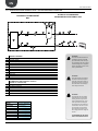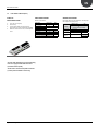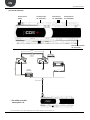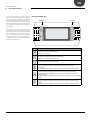
1
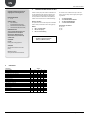
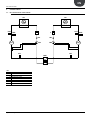
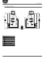
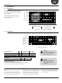
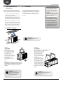
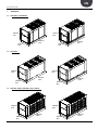
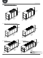
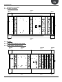
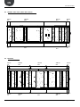
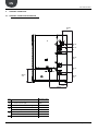
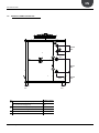
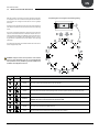
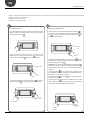
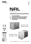
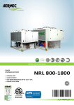
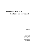
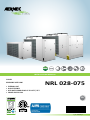
60Hz
INSTALLATION MANUAL
CHILLER
REVERSIBLE HEAT PUMP
• EXTERNAL UNIT
• HIGH EFFICENCY
• HOT WATER PRODUCING UP TO 131°F / 55°C
• POWER SUPPLY 60Hz
NRL 028-075
EN
11_14. 5641200_01
EN
NRL 0280-0750 60Hz
Dear Customer, Thank you for choosing an AERMEC product. This product is the result of many years of experience and in-depth engineering research, and it is built using top quality materials and advanced technologies.
In addition, the CE mark guarantees that our appliances fully comply with the requirements of the European
Machinery Directive in terms of safety. We constantly monitor the quality level of our products, and as a result
they are synonymous with Safety, Quality, and Reliability. Product data may be subject to modifications deemed necessary for improving the product without the obligation to give prior notice.
Thank you again.
AERMEC S.p.A
AERMEC S.p.A. reserves the right at all times to make any modification for the improvement of its product and is not obliged to add these modification to machines of
previous manufacture that have already been delivered or are being built.
11_14. 5641200_01
3
EN
NRL 0280-0750 60Hz
KEY:
2.
Check List.......................................................................................... 6
1.
Description And Choce Of Unit.......................................................... 6
3.
Cooling Circuit.................................................................................... 7
3.1.
Nrl Cooling Circuit Only Cooling......................................................... 7
3.2.
Nrl Cooling Circuit Heat Pump........................................................... 8
4.
Operation Limit.................................................................................. 9
4.1.
Cooling Mode ¹................................................................................... 9
4.2.
Heating Mode ¹.................................................................................. 9
5.
Selection And Place Of Installation.................................................. 10
5.1.
Minimum Technical.......................................................................... 10
6.
Positioning....................................................................................... 10
7.Dimension........................................................................................ 11
7.1.
Nrl 0280 E / Nrl 0280 He.................................................................. 11
7.2.
Nrl 0300 E........................................................................................ 11
7.3.
Nrl 0330 - 0350 E / Nrl 0300 - 0330 - 0350 He................................. 11
7.4.
Nrl 0500 - 0550 A / Nrl 0500 - 0550 Ha........................................... 12
7.5.
Nrl 0600 - 0650 - 0700 A / 0600 - 0650 - 0700 Ha........................... 12
7.6.
Nrl 0750 A........................................................................................ 12
7.7.
Nrl 0750 Ha...................................................................................... 12
8.
Antivibration Positioning.................................................................. 13
8.1.
Nrl 0280 E / Nrl 0280 He.................................................................. 13
8.2.
Nrl 0300 E........................................................................................ 13
8.3.
Nrl 0330 - 0350 E / Nrl 0300 - 0330 - 0350 He................................. 13
8.4.
Nrl 0500 - 0550 A / Nrl 0500 - 0550 Ha........................................... 13
8.5.
Nrl 0600 - 0650 - 0700 A / 0600 - 0650 - 0700 Ha........................... 14
8.6.
Nrl 0750 A........................................................................................ 14
8.7.
Nrl 0750 Ha...................................................................................... 15
9.
Hydraulic Connection....................................................................... 16
9.1.
Hydraulic Connection Nrl 0280-0700 .............................................. 16
9.2.
Hydraulic Connection Nrl 0750........................................................ 17
10.
Distribution Of Percentage Weights On Supportingpoints.............. 18
11.
Hydraulic Circuit............................................................................... 22
11.1.
Internal And External Hydraulic Circuit [Nrl Ha] "00" (Standard)..... 22
11.2.
Internal And External Hydraulic Circuit - Nrl Pump Version............ 23
11.3.
Internal And External Hydraulic Circuit - Nrl Pump Version ................ And Storage Tank............................................................................. 24
12.
Electronic Control(Pco5)................................................................... 25
13.
User Interface (Pgd1)....................................................................... 27
14.
Start-Up Procedure.......................................................................... 28
15.
Menu Structure And Navigation...................................................... 29
16.
User Operating Procedures.............................................................. 30
17.
Electronic Control(Gr3).................................................................... 31
18.
Electronic Control(Gr3).................................................................... 31
4
11_14. 5641200_01
EN
NRL 0280-0750 60Hz
11_14. 5641200_01
5
EN
NRL 0280-0750 60Hz
1.
Standards and Directives respected on
designing and constructing the unit:
DESCRIPTION AND CHOCE OF UNIT
Chillers and heat pumps for outdoor condensed in the
air with R410A Series NRL have been designed and
manufactured to satisfy heating and cooling needs
and the production of domestic hot water (DHW) in
medium to small commercial or residential buildings.
PROTECTION RATING
1. IP 24
Maximum reliability
The presence of several scroll compressors allows NRL
chillers various partialisations of the cooling capacity.
ACOUSTIC PART:
1. ISO DIS 9614/2
(INTENSIMETRIC METHOD))
2. SOUND POWER (EN ISO 9614-2)
3. SOUND PRESSURE (EN ISO 3744)
Models:
1. NRL "°" standard chiller
2. NRL "H" heat pump *
3. NRL "C" motocondensing
REFRIGERANT GAS:
This unit contains fluoride gases with
greenhouse effect covered by the
Kyoto Protocol. Maintenance and
disposal must only be performed by
qualified staff.
The versions can be in different set-ups at the same
time in order to satisfy a wide range of plant engineering solutions:
1.
2.
3.
4.
"A" HIGH EFFICIENCY
"E" SILENCED HIGH EFFICIENCY
"D" WITH DESUPERHEATER
"T" WITH TOTAL RECOVERY
Configurations not allowed:
YD / YT / YH
HT / HC
TC / DC
* Possibility of production of D.H.W.
(DCPX_UL | VMF-ACS | AER485).
STANDARD:
UL 1995
Heating and cooling equipment.
ANSI/NFPA
Standard 70 National Electrical code
(N.E.C.).
CSA C.22.1.- C.22.2
Safety Standard Electrical Installation.
2.
CHECK LIST
COMPONENTS
COOLING CIRCUIT
VERSIONS
°
H
C
D
T
THERMOSTATIC VALVE X - Y (CONFIGURATION OPTION)
yes
yes
no
no
no
EXCHANGER PLATE (EVAPORATOR)
yes
yes
no
yes
yes
EXCHANGER PLATE (TOTAL RECOVERY)
no
no
no
no
yes
EXCHANGER PLATE (DESUPERHEATER)
no
no
no
yes
no
AIR SIDE EXCHANGE
yes
yes
yes
yes
yes
COMPRESSOR
yes
yes
yes
yes
yes
DEHYDRATOR FILTER
yes
yes
yes
yes
yes
HIGH PRESSURE SWITCH
yes
yes
yes
yes
yes
LOW PRESSURE SWITCH
no
no
no
no
no
HIGH PRESSURE TRANSDUCER
yes
yes
yes
yes
yes
LOW PRESSURE TRANSDUCER
yes
yes
yes
yes
yes
LIQUID INDICATOR
yes
yes
yes
yes
yes
LIQUID TANK
no
yes
no
no
yes
ONE-WAY VALVES
no
yes
no
no
yes
LIQUID SEPARATOR
no
yes
no
no
yes
CYCLE REVERSE VALVE
no
yes
no
no
yes
6
11_14. 5641200_01
EN
NRL 0280-0750 60Hz
3.
COOLING CIRCUIT
3.1. NRL COOLING CIRCUIT ONLY COOLING
CN
HPT
HPS
CP
LPT
CN
F
F
IDL
IDL
TEV
TEV
BHE
HPT
HPS
CP
LPT
KEY
KEY
BHE:
A PIASTRE
BHE SCAMBIATORE
EXCHANGER PLATE
CN: BATTERIA ALETTATA
CN AIR SIDE EXCHANGE
CP: COMPRESSORE
COMPRESSOR
F: CP
FILTRO
DEIDRATATORE
HPS:
ALTA PRESSIONE
F PRESSOSTATO
DEHYDRATOR DI
FILTER
HPT: TRASDUTTORE ALTA PRESSIONE
HPS
HIGH
PRESSURE
SWITCH
IDL: INDICATORE DI LIQUIDO
LPT:
BASSA
PRESSIONE
HPTTRASDUTTORE
HIGH PRESSURE
TRANSDUCER
IDL LIQUID INDICATOR
LPT LOW PRESSURE TRANSDUCER
11_14. 5641200_01
7
EN
NRL 0280-0750 60Hz
3.2. NRL COOLING CIRCUIT HEAT PUMP
CN
CV
CN
CV
CV
CV
AL
AL
VIC
VIC
F
F
HPT
IDL
LPT
CV
HPT
HPS
CP
TEV
CV
HPS
IDL
CP
LS
LS
BHE
TEV
LPT
CV
CV
KEY
KEY
AL
BHE
CN
CP
CV
F
HPS
HPT
IDL
LPT
LS
VIC
8
AL: ACCUMULO DEL LIQUIDO
BHE: SCAMBIATORE A PIASTRE
CN: BATTERIA ALETTATA
CP: COMPRESSORE
CV: VALVOLA DI NON RITORNO
F: FILTRO DEIDRATATORE
HPS: PRESSOSTATO DI ALTA PRESSIONE
HPT: TRASDUTTORE ALTA PRESSIONE
IDL: INDICATORE DI LIQUIDO
LPT: TRASDUTTORE BASSA PRESSIONE
LS: SEPARATORE DI LIQUIDO
VIC: VALVOLA INVERSIONE CICLO
LIQUID TANK
EXCHANGER PLATE
AIR SIDE EXCHANGE
COMPRESSOR
ONE-WAY VALVES
DEHYDRATOR FILTER
HIGH PRESSURE SWITCH
HIGH PRESSURE TRANSDUCER
LIQUID INDICATOR
LOW PRESSURE TRANSDUCER
LIQUID SEPARATOR
CYCLE INVERSION VALVE
11_14. 5641200_01
EN
NRL 0280-0750 60Hz
4.
OPERATION LIMIT
4.1. COOLING MODE ¹
-5
-10
-15
Functioning with
glycoled water
STANDARD
functioning
Functioning only with "I"
funs +
water glycoled
24,8
26,6
28,4
30,2
32,0
33,8
35,6
37,4
17,6
19,4
21,2
23,0
Functioning only with "I" funs
Thermostatic valve Y
66,2 19
68,0 20
23
14
5
46 °C 114,8 °F
36 °C
96,8 °F
39,2
41,0
42,8
44,6 7
46,4 8
48,2 9
50,0 10
51,8 11
53,6 12
55,4 13
57,2 14
59,0 15
60,8 16
62,6 17
64,4 18
°C
50
45
40
35
30
25
20
15
10
5
0
-8
-7
-6
-5
-4
-3
-2
-1
Wind breaks should be implemented if the unit is
installed in particularly windy areas, to prevent a
malfunction of the unit.
°F
122
113
104
95
86
77
68
59
50
41
32
0
1
2
3
4
5
6
External air temperature b.s.
The units, in standard configuration, are not suitable
for installation in salty environments. For functioning limits, please refer to the diagrams below, valid for AHRI
standard conditions.
°C
°F
Thermostatic valve °
Thermostatic valve X
Temperature of the water produced EVAPORATOR
Temperature of the water
produced CONDENSER
4.2. HEATING MODE ¹
°F °C
140 60
131 55
55 °C 131 °F
122 50
113 45
104 40
35
30
25
20
15
95
86
77
68
59
Functioning
only with "I"
funs
STANDARD
functioning
-15 °C
5 °F
-20
-4
-15
5
42 °C
107,6 °F
-10
14
-5
23
0
32
5
41
10
50
15
59
20
68
25
77
30
86
35
95
40
104
45
113
50 °C
122 °F
External air temperature b.s.
REFRIGERANT SIDE
High pressure
Low pressure
side
side
Acceptable maximum pressure
bar/PSI
45/653
30/435
Acceptable maximum temperature
Acceptable minimum temperature
°C / °F
°C / °F
120 / 257
-30 /- 22
51 / 131
-30 / -22
WATER SIDE
Acceptable maximum pressure
bar/PSI
6/87
Hydarulic circuit safety valve
(only in version with storage tank or with pump)
Calibrated at 6/87 bar/PSI and with piped discharge, which intervents
by discharging overpressure if abnormal work pressure occur.
Note:
1 - In summer mode the unit can be started
with external air 46°C/114,8°F and water inlet
35°C/95°F. In winter mode the unit can be started
with external air -15°C/5°F and water inlet
11_14. 5641200_01
20°C/68°F. Operate in such conditions is permitted only for a short time and to bring the system
up to temperature. To reduce the time of this
operation, it is recommended to install a threeway valve that allows bypassing water from the
ATTENTION
Contact our technical sales department if the unit needs to operated
outside the operating limits.
ATTENTION
If the unit is installed in particularly windy areas, we recommend
providing for windbreak to avoid
malfunctioning
system utilities, until the conditions that allow
the unit to work within the permitted operation
limits are achieved.
9
EN
NRL 0280-0750 60Hz
5.
SELECTION AND PLACE OF
INSTALLATION
6.
Prima di procedere all'installazione dell'unità
concordare con il cliente la posizione dove andrà
collocata, ponendo attenzione ai punti seguenti:
−
−
−
The support surface must be capable of
supporting the unit weight.
The safety differences between the unit
and other appliances or structures must
be scrupulously respected so that the inlet
and outlet air from the fans is free to circulate.
The unit must be installed by an enabled
technician in compliance with the national
legislation in force in the country of destination, respecting the minimum technical
spaces in order to allow maintenance.
POSITIONING
The machine is delivered from the factory wrapped
in estincoil. Before handling the unit, verify the
lifting capacity of the machines used. After removal
of packaging, movement of apparatus must be
carried out by qualified and adequately equipped
personnel.
The unit must be installed by a qualified and suitably trained technician,
in compliance with the national
legislation in force in the country
of destination (Ministerial Decree
329/2004).
AERMEC will not assume any responsibility for damage due to failure to
follow these instructions.
Before beginning any operation,
READ THESE INSTRUCTIONS CAREFULLY AND CARRY OUT THE SAFETY
CHECKS TO REDUCE ALL RISK OF
DANGER TO A MINIMUM. All the
staff involved must have thorough
knowledge of the operations and
any dangers that may arise at the
moment in which the installation
operations are carried out.
5.1. MINIMUM TECHNICAL
3000 mm
118 in
800 mm
31 in
800 mm
31 in
1100 mm
43 in
800 mm
31 in
EXAMPLE 1
"OF THE LIFTING"
Size 0280-0700.
Insert pipes (NOT SUPPLIED) in
holes on the base with length
such to allow positioning of the
belts used for lifting.
To prevent the unit structure
being damaged by the belts place
protections between the latter
and the machine.
It is prohibited to stop under
the unit.
NOTE:
The appliance warranty does not cover the costs for ladders, scaffolding, or other elevation systems that may
become necessary for carrying out servicing under
warranty.
ATTENTION
L'unità viene fornita fissata su di
un pallet, per la movimentazione
con carri elevatori e cinghie prevedere dei pali (NON FORNITI).
10
ATTENTION:
The drawings are only examples.
EXAMPLE 2
"OF THE LIFTING"
NRL 0750 (always use all the provided eyebolts)
Before moving the unit, check the lifting
capacity of the machines used.
Once the packaging has been
removed, the unit must
be handled by qualified personnel, using the appropriate
equipment.
To handle the machine:
"IN THE EVENT OF LIFTING",
hook the lifting cables to the
special eyebolts In order to
avoid damaging the unit with
the cables, insert protection
elements between them and
the machine. Is it absolutely
forbidden to stand beneath
the unit.
ATTENTION
Always use all the provided eyebolts.
11_14. 5641200_01
EN
NRL 0280-0750 60Hz
7.
DIMENSION
7.1. NRL 0280 E / NRL 0280 HE
1606 mm
63 in
1100 mm
43 in
1750 mm
69 in
2450 mm
96 in
1160 mm
46 in
2510 mm
99 in
7.2. NRL 0300 E
1606 mm
63 in
1750 mm
69 in
2950 mm
116 in
1100 mm
43 in
3010 mm
119 in
1160 mm
46 in
7.3. NRL 0330 - 0350 E / NRL 0300 - 0330 - 0350 HE
1606 mm
63 in
1100 mm
43 in
11_14. 5641200_01
1750 mm
69 in
2950 mm
116 in
1160 mm
46 in
3010 mm
119 in
11
EN
NRL 0280-0750 60Hz
7.4. NRL 0500 - 0550 A / NRL 0500 - 0550 HA
2035 mm
80 in
1875 mm
74 in
1100 mm
43 in
2950 mm
116 in
3010 mm
119 in
1160 mm
46 in
7.5. NRL 0600 - 0650 - 0700 A / 0600 - 0650 - 0700 HA
1875 mm
74 in
1990 mm
78 in
3950 mm
156 in
4010 mm
158 in
1100 mm
43 in
1160 mm
46 in
7.6. NRL 0750 A
7.7. NRL 0750 HA
1975 mm
78 in
1975 mm
78 in
4350 mm
171 in
1500 mm
59 in
12
5355 mm
211 in
1500 mm
59 in
ATTENTION:
NRL 0750 A-HA ALWAYS USE ALL THE PROVIDED EYEBOLTS.
11_14. 5641200_01
EN
NRL 0280-0750 60Hz
8.
ANTIVIBRATION POSITIONING
8.1. NRL 0280 E / NRL 0280 HE
200 mm
8 in
2050 mm
81 in
200 mm
8 in
200 mm
8 in
2050 mm
81 in
200 mm
8 in
8.2. NRL 0300 E
8.3. NRL 0330 - 0350 E / NRL 0300 - 0330 - 0350 HE
8.4. NRL 0500 - 0550 A / NRL 0500 - 0550 HA
200 mm
8 in
1275 mm
50 in
1275 mm
50 in
200 mm
8 in
200 mm
8 in
1275 mm
50 in
1275 mm
50 in
200 mm
8 in
11_14. 5641200_01
13
EN
NRL 0280-0750 60Hz
8.5. NRL 0600 - 0650 - 0700 A / 0600 - 0650 - 0700 HA
200 mm
8 in
2100 mm
83 in
1450 mm
57 in
200 mm
8 in
200 mm
8 in
2100 mm
83 in
1450 mm
57 in
200 mm
8 in
100 mm
4 in
8.6. NRL 0750 A
14
100 mm
4 in
1500 mm
59 in
1150 mm
45 in
1500 mm
59 in
100 mm
4 in
1500 mm
59 in
1150 mm
45 in
1500 mm
59 in
100 mm
4 in
11_14. 5641200_01
EN
NRL 0280-0750 60Hz
8.7. NRL 0750 HA
100 mm
4 in
2000 mm
79 in
100 mm
4 in
2000 mm
79 in
11_14. 5641200_01
1150 mm
45 in
2000 mm
79 in
100 mm
4 in
2000 mm
79 in
100 mm
4 in
15
EN
NRL 0280-0750 60Hz
9.
HYDRAULIC CONNECTION
9.1. HYDRAULIC CONNECTION NRL 0280-0700
150 mm
6 in
D
E
110 mm
4 in
157 mm
6 in
F
470 mm
19 in
B
A
C
240 mm
9 in
428 mm
17 in
340 mm
13 in
248 mm
10 in
550 mm
22 in
KEY
A IN - version with pump
B
IN - standard version [00]
Ø 2½"
C
OUT - standard versions and storage tank
Ø 2½"
IN - desuperheater
Ø 1½"
D
E
F
16
CONNECTIONS
Ø 2½"
IN - total recovery
Ø 2½"
OUT - desuperheater
Ø 1½"
OUT - total recovery
Ø 2½"
IN - versions with storage tank
Ø 2½"
11_14. 5641200_01
EN
NRL 0280-0750 60Hz
9.2. HYDRAULIC CONNECTION NRL 0750
D
250 mm
10 in
C
A
304 mm
12 in
497 mm
20 in
B
300 mm
12 in
100 mm
4 in
KEY
A
B
C
100 mm
4 in
IN - standard version [00] and pump
CONNECTIONS
Ø3"
IN - version with storage tank
Ø4"
OUT - standard version [00] and pump
Ø3"
OUT - version with storage tank Ø4"
IN - desuperheater
Ø1½"
D OUT - desuperheater
11_14. 5641200_01
436 mm
17 in
Ø1½"
17
EN
NRL 0280-0750 60Hz
10. DISTRIBUTION OF PERCENTAGE WEIGHTS ON SUPPORTINGPOINTS
Gy
1
3
2
4
Gx
TOP VIEW
WEIGHT OF EMPTY UNITS
NRL
TYPE
WEIGHT
(lib)
CENTER OF
GRAVITY
Gx mm Gx in
WEIGHT OF RUNNING UNITS
PERCENTAGE OF WEIGHT
DISTRIBUTION SUPPORTS (%)
Gy mm
Gy in
1
2
3
4
KIT
VT
NRL
TYPE
WEIGHT
(lib)
CENTER OF
GRAVITY
Gx mm Gx in
PERCENTAGE OF WEIGHT
DISTRIBUTION SUPPORTS (%)
Gy
Gy in
1
2
3
4
KIT
VT
NRL0280E 00
1401
558
21,97
965
37,99
25%
28%
22%
25%
VT 17
NRL0280E 00
1432
550
21,65
974 38,35
25%
27%
23%
25%
VT 17
NRL0280E 02-04
1809
557
21,93
1146 45,12
21%
23%
27%
29%
VT 13
NRL0280E 02-04
2501
550
21,65 1253 49,33
19%
20%
29%
32%
VT 13
NRL0280E 01-03
1732
557
21,93
1102 43,39
22%
24%
26%
28%
VT 13
NRL0280E 01-03
2424
550
21,65 1225 48,23
19%
21%
29%
31%
VT 13
NRL0280E P2-P4
1555
558
21,97
1082 42,60
22%
25%
25%
28%
VT 17
NRL0280E P2-P4
1587
550
21,65 1088 42,83
23%
24%
26%
28%
VT 17
NRL0280E P1-P3
1478
558
21,97
1026 40,39
24%
26%
24%
26%
VT 17
NRL0280E P1-P3
1509
550
21,65 1034 40,71
24%
26%
24%
26%
VT 17
NRL0300E 00
1547
558
21,97
995
39,17
24%
27%
23%
26%
VT 17
NRL0300E 00
1587
548
21,57 1005 39,57
25%
26%
24%
25%
VT 17
NRL0300E 02-04
1955
556
21,89
1157 45,55
21%
23%
27%
30%
VT 13
NRL0300E 02-04
2656
549
21,61 1256 49,45
19%
20%
30%
32%
VT 13
NRL0300E 01-03
1878
557
21,93
1116 43,94
22%
24%
26%
29%
VT 13
NRL0300E 01-03
2579
549
21,61 1229 48,39
19%
21%
29%
31%
VT 13
NRL0300E P2-P4
1701
557
21,93
1099 43,27
22%
24%
25%
28%
VT 17
NRL0300E P2-P4
1741
548
21,57 1106 43,54
22%
24%
26%
28%
VT 17
NRL0300E P1-P3
1624
558
21,97
1050 41,34
23%
26%
24%
27%
VT 17
NRL0300E P1-P3
1664
548
21,57 1058 41,65
23%
25%
25%
27%
VT 17
NRL0330E 00
1568
558
21,97
1155 45,47
26%
29%
21%
24%
VT 17
NRL0330E 00
1611
549
21,61 1164 45,83
26%
28%
22%
24%
VT 17
NRL0330E 02-04
1976
556
21,89
1282 50,47
24%
26%
24%
26%
VT 13
NRL0330E 02-04
2680
549
21,61 1349 53,11
23%
24%
25%
27%
VT 13
NRL0330E 01-03
1899
557
21,93
1246 49,06
24%
27%
23%
26%
VT 13
NRL0330E 01-03
2603
549
21,61 1325 52,17
23%
25%
25%
27%
VT 13
NRL0330E P2-P4
1722
557
21,93
1243 48,94
24%
27%
23%
26%
VT 17
NRL0330E P2-P4
1765
549
21,61 1250 49,21
25%
26%
24%
25%
VT 17
NRL0330E P1-P3
1645
558
21,97
1201 47,28
25%
28%
22%
25%
VT 17
NRL0330E P1-P3
1688
549
21,61 1209 47,60
25%
27%
23%
25%
VT 17
NRL0350E 00
1711
558
21,97
1192 46,93
25%
28%
22%
25%
VT 17
NRL0350E 00
1754
549
21,61 1200 47,24
26%
27%
23%
24%
VT 17
NRL0350E 02-04
2119
556
21,89
1303 51,30
23%
26%
24%
27%
VT 13
NRL0350E 02-04
2824
550
21,65 1362 53,62
22%
24%
26%
28%
VT 13
NRL0350E 01-03
2042
557
21,93
1271 50,04
24%
26%
24%
26%
VT 13
NRL0350E 01-03
2746
550
21,65 1340 52,76
23%
25%
25%
27%
VT 13
NRL0350E P2-P4
1866
557
21,93
1271 50,04
24%
26%
24%
26%
VT 17
NRL0350E P2-P4
1909
549
21,61 1276 50,24
24%
26%
24%
26%
VT 17
NRL0350E P1-P3
1789
558
21,97
1233 48,54
24%
27%
23%
25%
VT 17
NRL0350E P1-P3
1832
549
21,61 1240 48,82
25%
27%
23%
25%
VT 17
NRL0500A 00
1869
568
22,36
1197 47,13
29%
31%
20%
21%
VT 13
NRL0500A 00
1916
560
22,05 1209 47,60
29%
30%
20%
21%
VT 13
NRL0500A 02-04
2328
564
22,20
1410 55,51
25%
27%
23%
25%
VT 10
NRL0500A 02-04
3477
555
21,85 1583 62,32
23%
23%
27%
27%
VT 10
NRL0500A 01-03
2242
565
22,24
1355 53,35
26%
28%
22%
24%
VT 10
NRL0500A 01-03
3391
555
21,85 1551 61,06
23%
24%
26%
27%
VT 10
NRL0500A P2-P4
2041
566
22,28
1335 52,56
27%
28%
22%
23%
VT 13
NRL0500A P2-P4
2088
559
22,01 1342 52,83
27%
28%
22%
23%
VT 13
NRL0500A P1-P3
1955
567
22,32
1269 49,96
28%
29%
21%
22%
VT 13
NRL0500A P1-P3
2002
559
22,01 1278 50,31
28%
29%
21%
22%
VT 13
NRL0550A 00
2075
569
22,40
1254 49,37
28%
30%
21%
22%
VT 13
NRL0550A 00
2128
561
22,09 1263 49,72
28%
29%
21%
22%
VT 13
NRL0550A 02-04
2534
565
22,24
1439 56,65
25%
26%
24%
25%
VT 10
NRL0550A 02-04
3689
556
21,89 1593 62,72
23%
23%
27%
27%
VT 10
NRL0550A 01-03
2448
566
22,28
1390 54,72
26%
27%
23%
24%
VT 10
NRL0550A 01-03
3603
557
21,93 1563 61,54
23%
24%
26%
27%
VT 10
NRL0550A P2-P4
2247
567
22,32
1375 54,13
26%
28%
23%
24%
VT 13
NRL0550A P2-P4
2300
560
22,05 1380 54,33
26%
27%
23%
24%
VT 13
NRL0550A P1-P3
2161
568
22,36
1317 51,85
27%
29%
22%
23%
VT 13
NRL0550A P1-P3
2214
561
22,09 1324 52,13
27%
28%
22%
23%
VT 13
18
11_14. 5641200_01
EN
NRL 0280-0750 60Hz
WEIGHT OF EMPTY UNITS
NRL0600A
CENTER OF
PERCENTAGE OF WEIGHT
WEIGHT
KIT
GRAVITY
DISTRIBUTION SUPPORTS (%)
TYPE
Gx
Gy
(lib)
VT
Gx in
Gy in
1
2
3
4
5
6
mm
mm
00
2425
553 21,77 1706 67,17 5,6% 5,6% 33,2% 33,6% 11,0% 11,1% VT 22
NRL0600A
02-04
2932
553 21,77 1821 71,69
3,7%
3,7% 34,8% 35,1% 11,3% 11,4% VT 22
NRL0600A
01-03
2822
553 21,77 1801 70,91
4,0%
4,1% 34,5% 34,8% 11,3% 11,4% VT 22
NRL0600A
P2-P4
2668
553 21,77 1766 69,53
4,6%
4,7% 34,0% 34,3% 11,2% 11,3% VT 22
NRL0600A
P1-P3
2557
553 21,77 1740 68,50
5,0%
5,1% 33,6% 34,0% 11,1% 11,2% VT 22
NRL0650A
00
2447
551 21,69 1695 66,73
5,7%
5,8% 33,3% 33,3% 10,9% 11,0% VT 22
NRL0650A
02-04
2954
550 21,65 1811 71,30
3,8%
3,8% 34,8% 34,9% 11,3% 11,3% VT 22
NRL0650A
01-03
2844
550 21,65 1791 70,51
4,2%
4,2% 34,5% 34,6% 11,2% 11,3% VT 22
NRL0650A
P2-P4
2690
550 21,65 1755 69,09
4,8%
4,8% 34,0% 34,1% 11,1% 11,1% VT 22
NRL0650A
P1-P3
2579
550 21,65 1729 68,07
5,2%
5,2% 33,7% 33,8% 11,0% 11,1% VT 22
NRL0700A
00
2447
557 21,93 1679 66,10
5,9%
6,0% 32,8% 33,6% 10,7% 11,0% VT 22
NRL0700A
02-04
2954
555 21,85 1798 70,79
4,0%
4,1% 34,4% 35,1% 11,1% 11,4% VT 22
NRL0700A
01-03
2844
556 21,89 1777 69,96
4,4%
4,4% 34,1% 34,8% 11,1% 11,3% VT 22
NRL0700A
P2-P4
2690
556 21,89 1741 68,54
4,9%
5,1% 33,6% 34,3% 10,9% 11,2% VT 22
NRL0700A
P1-P3
2579
556 21,89 1714 67,48
5,4%
5,5% 33,2% 34,0% 10,8% 11,1% VT 22
NRL
Gy
Gx
1
3
5
2
4
6
WEIGHT OF RUNNING UNITS
CENTER OF
PERCENTAGE OF WEIGHT
WEIGHT
KIT
GRAVITY
DISTRIBUTION SUPPORTS (%)
NRL
TYPE
Gx
Gy
(lib)
VT
Gx in
Gy in
1
2
3
4
5
6
mm
mm
NRL0600A 00
2491 547 21,54 1715 67,52 5,5% 5,4% 33,7% 33,3% 11,1% 11,0% VT 22
NRL0600A 02-04
4079
548 21,57 1979 77,91 0,6%
0,6% 37,5% 37,3% 12,0% 11,9% VT 22
NRL0600A 01-03
3968
548 21,57 1969 77,52 0,8%
0,8% 37,4% 37,1% 12,0% 11,9% VT 22
NRL0600A P2-P4
2712
547 21,54 1773 69,80 4,6%
4,5% 34,4% 34,1% 11,3% 11,2% VT 22
NRL0600A P1-P3
2601
547 21,54 1748 68,82 5,0%
4,9% 34,1% 33,7% 11,2% 11,1% VT 22
NRL0650A 00
2513
545 21,46 1704 67,09 5,7%
5,6% 33,7% 33,1% 11,1% 10,9% VT 22
NRL0650A 02-04
4101
547 21,54 1971 77,60 0,8%
0,7% 37,6% 37,1% 12,0% 11,8% VT 22
NRL0650A 01-03
4012
547 21,54 1960 77,17 1,0%
1,0% 37,4% 36,9% 11,9% 11,8% VT 22
NRL0650A P2-P4
2756
545 21,46 1762 69,37 4,7%
4,6% 34,5% 33,9% 11,3% 11,0% VT 22
NRL0650A P1-P3
2646
545 21,46 1737 68,39 5,1%
5,0% 34,2% 33,5% 11,2% 11,0% VT 22
NRL0700A 00
2535
547 21,54 1693 66,65 5,8%
5,7% 33,5% 33,1% 11,0% 10,8% VT 22
NRL0700A 02-04
4123
548 21,57 1963 77,28 0,9%
0,9% 37,4% 37,1% 11,9% 11,8% VT 22
NRL0700A 01-03
4034
548 21,57 1952 76,85 1,1%
1,1% 37,2% 37,0% 11,9% 11,8% VT 22
NRL0700A P2-P4
2778
547 21,54 1752 68,98 4,9%
4,8% 34,2% 33,9% 11,1% 11,0% VT 22
NRL0700A P1-P3
2668
547 21,54 1727 67,99 5,3%
5,2% 33,9% 33,6% 11,1% 11,0% VT 22
TOP VIEW
Gy
Gx
TOP VIEW
1
3
5
7
2
4
6
8
WEIGHT OF EMPTY UNITS
CENTER OF
GRAVITY
PERCENTAGE OF WEIGHT
DISTRIBUTION SUPPORTS (%)
TYPE
WEIGHT
(lib) WEIGHT
NRL0750A
00
3571
755
29,72
1840
NRL0750A
02-04
4167
754
29,69
1919
NRL0750A
01-03
4034
754
29,69
NRL0750A
P2-P4
3858
754
NRL0750A
P1-P3
3726
754
NRL
Gx mm
Gx in
Gy mm
Gy in
KIT
VT
1
2
3
4
5
6
7
8
72,44
8,4%
8,5%
18,2%
18,5%
20,8%
21,0%
2,3%
2,3%
VT 23
75,55
7,4%
7,5%
18,0%
18,2%
22,5%
22,8%
1,8%
1,8%
VT 23
1904
74,96
7,6%
7,7%
18,1%
18,3%
22,2%
22,4%
1,9%
1,9%
VT 23
29,69
1881
74,06
7,9%
8,0%
18,1%
18,3%
21,7%
21,9%
2,0%
2,1%
VT 23
29,69
1863
73,35
8,1%
8,2%
18,2%
18,4%
21,3%
21,5%
2,1%
2,2%
VT 23
7
8
WEIGHT OF RUNNING UNITS
NRL
TYPE
WEIGHT
(lib) WEIGHT
CENTER OF
GRAVITY
Gx
Gx in
PERCENTAGE OF WEIGHT
DISTRIBUTION SUPPORTS (%)
Gy
Gy in
1
2
3
4
5
6
KIT
VT
NRL0750A
00
3660
746
29,37
1847 72,72
8,5%
8,4%
18,4%
18,2%
21,1%
20,9%
2,3%
2,3%
NRL0750A
02-04
5798
747
29,41
2048 80,63
5,5%
5,5%
17,8%
17,7%
26,0%
25,8%
0,9%
0,9%
VT 23
VT 23
NRL0750A
01-03
5666
747
29,41
2040 80,31
5,7%
5,6%
17,8%
17,7%
25,7%
25,6%
0,9%
0,9%
VT 23
NRL0750A
P2-P4
3946
746
29,37
1886 74,25
7,9%
7,8%
18,3%
18,1%
22,0%
21,7%
2,0%
2,0%
VT 23
NRL0750A
P1-P3
3814
746
29,37
1869 73,58
8,2%
8,1%
18,4%
18,2%
21,6%
21,3%
2,2%
2,1%
VT 23
11_14. 5641200_01
19
EN
NRL 0280-0750 60Hz
Gy
1
3
2
4
Gx
TOP VIEW
WEIGHT OF RUNNING UNITS
WEIGHT OF EMPTY UNITS
NRL
TYPE
NRL0280HE 00
WEIGHT
(lib)
1589
CENTER OF
GRAVITY
Gx mm
557
Gx in
21,95
PERCENTAGE OF WEIGHT
DISTRIBUTION SUPPORTS (%)
Gy mm
984
Gy in
38,73
1
25%
2
27%
3
23%
4
25%
KIT
VT
NRL
TYPE
WEIGHT
(lib)
CENTER OF
GRAVITY
Gx mm
Gx in
Gy
Gy in
PERCENTAGE OF WEIGHT
DISTRIBUTION SUPPORTS (%) KIT
VT
1
2
3
4
VT 17
NRL0280HE 00
1626
550
21,66
991 39,00
25%
27%
23%
25%
VT 17
NRL0280HE 02-04
2695
550
21,66
1243 48,95
19%
20%
29%
31%
VT 13
NRL0280HE 02-04
1997
556
21,89
1144 45,04
21%
23%
27%
29%
VT 13
NRL0280HE 01-03
1920
556
21,90
1104 43,46
22%
24%
26%
28%
VT 13
NRL0280HE 01-03
2618
550
21,66
1217 47,90
20%
21%
29%
31%
VT 13
NRL0280HE P2-P4
1780
550
21,66
1091 42,94
23%
24%
26%
28%
VT 17
NRL0280HE P2-P4
1744
557
21,92
1087 42,78
22%
25%
25%
28%
VT 17
NRL0280HE P1-P3
1667
557
21,93
1038 40,85
23%
26%
24%
27%
VT 17
NRL0280HE P1-P3
1703
550
21,66
1043 41,06
24%
25%
24%
26%
VT 17
1808
548
21,59
1196 47,08
26%
27%
23%
24%
VT 17
2878
549
21,62
1356 53,39
23%
24%
26%
28%
VT 13
NRL0300HE 00
1765
557
21,93
1188 46,78
25%
28%
22%
24%
VT 17
NRL0300HE 00
NRL0300HE 02-04
2173
556
21,88
1297 51,07
23%
26%
24%
27%
VT 13
NRL0300HE 02-04
NRL0300HE 01-03
2096
556
21,88
1266 49,84
24%
26%
24%
26%
VT 13
NRL0300HE 01-03
2800
549
21,61
1334 52,54
23%
25%
25%
27%
VT 13
NRL0300HE P2-P4
1963
549
21,60
1271 50,02
24%
26%
24%
26%
VT 17
NRL0300HE P2-P4
1920
556
21,91
1265 49,80
24%
26%
24%
26%
VT 17
NRL0300HE P1-P3
1843
557
21,92
1228 48,35
25%
27%
23%
25%
VT 17
NRL0300HE P1-P3
1886
549
21,60
1235 48,61
25%
27%
23%
25%
VT 17
1823
549
21,60
1190 46,87
26%
28%
23%
24%
VT 17
2892
549
21,62
1352 53,23
23%
24%
26%
27%
VT 13
NRL0330HE 00
1775
557
21,94
1184 46,60
25%
28%
22%
24%
VT 17
NRL0330HE 00
NRL0330HE 02-04
2183
556
21,88
1293 50,90
23%
26%
24%
27%
VT 13
NRL0330HE 02-04
NRL0330HE 01-03
2106
556
21,89
1262 49,68
24%
26%
24%
26%
VT 13
NRL0330HE 01-03
2815
549
21,62
1330 52,37
23%
25%
25%
27%
VT 13
NRL0330HE P2-P4
1977
549
21,61
1265 49,80
24%
26%
24%
26%
VT 17
NRL0330HE P2-P4
1930
557
21,91
1261 49,63
24%
27%
23%
26%
VT 17
NRL0330HE P1-P3
1853
557
21,92
1224 48,18
25%
27%
23%
25%
VT 17
NRL0330HE P1-P3
1900
549
21,60
1229 48,39
25%
27%
23%
25%
VT 17
2001
549
21,63
1212 47,72
29%
29%
21%
21%
VT 17
3070
550
21,64
1357 53,41
23%
24%
26%
28%
VT 13
NRL0350HE 00
1948
557
21,93
1208 47,55
25%
28%
22%
25%
VT 17
NRL0350HE 00
NRL0350HE 02-04
2356
556
21,88
1305 51,37
23%
26%
24%
27%
VT 13
NRL0350HE 02-04
NRL0350HE 01-03
2279
556
21,89
1276 50,25
24%
26%
24%
26%
VT 13
NRL0350HE 01-03
2993
550
21,64
1336 52,61
23%
25%
25%
27%
VT 13
2155
549
21,63
1279 50,35
24%
26%
24%
26%
VT 17
NRL0350HE P2-P4
2103
557
21,91
1276 50,26
24%
26%
24%
26%
VT 17
NRL0350HE P2-P4
NRL0350HE P1-P3
2025
557
21,92
1243 48,95
24%
27%
23%
26%
VT 17
NRL0350HE P1-P3
2078
549
21,63
1247 49,08
25%
26%
24%
25%
VT 17
NRL0500HA 00
2181
565
22,26
1236 48,65
28%
30%
20%
22%
VT 13
NRL0500HA 00
2237
558
21,98
1244 48,97
28%
29%
21%
21%
VT 13
NRL0500HA 02-04
2639
563
22,15
1416 55,76
25%
27%
23%
25%
VT 10
NRL0500HA 02-04
3798
555
21,85
1572 61,88
23%
24%
26%
27%
VT 10
NRL0500HA 01-03
2553
563
22,17
1369 53,89
26%
27%
23%
24%
VT 10
NRL0500HA 01-03
3712
555
21,85
1543 60,74
24%
24%
26%
26%
VT 10
NRL0500HA P2-P4
2353
564
22,22
1352 53,22
26%
28%
22%
24%
VT 13
NRL0500HA P2-P4
2409
558
21,96
1357 53,42
27%
27%
23%
23%
VT 13
NRL0500HA P1-P3
2267
565
22,24
1296 51,02
27%
29%
21%
23%
VT 13
NRL0500HA P1-P3
2323
558
21,97
1302 51,28
28%
28%
22%
22%
VT 13
NRL0550HA 00
2219
567
22,34
1226 48,28
28%
30%
20%
21%
VT 13
NRL0550HA 00
2282
560
22,06
1234 48,59
29%
30%
21%
21%
VT 13
NRL0550HA 02-04
2678
564
22,22
1406 55,35
25%
27%
23%
24%
VT 10
NRL0550HA 02-04
3843
556
21,89
1562 61,51
23%
24%
26%
27%
VT 10
NRL0550HA 01-03
2592
565
22,24
1359 53,50
26%
28%
22%
24%
VT 10
NRL0550HA 01-03
3757
556
21,90
1533 60,37
24%
24%
26%
26%
VT 10
NRL0550HA P2-P4
2391
566
22,29
1341 52,81
26%
28%
22%
23%
VT 13
NRL0550HA P2-P4
2454
560
22,03
1346 52,98
27%
28%
22%
23%
VT 13
NRL0550HA P1-P3
2305
567
22,31
1286 50,63
27%
29%
21%
22%
VT 13
NRL0550HA P1-P3
2368
560
22,04
1292 50,87
28%
29%
22%
22%
VT 13
20
11_14. 5641200_01
EN
NRL 0280-0750 60Hz
WEIGHT OF EMPTY UNITS
NRL
CENTER OF
WEIGHT
GRAVITY
TYPE
Gx
Gy
(lib)
Gx in
mm
mm
PERCENTAGE OF WEIGHT
DISTRIBUTION SUPPORTS (%)
Gy in
1
2
3
4
5
6
KIT
VT
NRL0600HA 00
2866
553 21,77 1781 70,12
4,9%
4,9%
33,4% 33,7% 11,4% 11,5% VT 22
NRL0600HA 02-04
3351
552 21,73 1871 73,66
3,2%
3,3%
34,8% 35,1% 11,7% 11,8% VT 22
NRL0600HA 01-03
3263
552 21,73 1854 72,99
3,6%
3,6%
34,6% 34,8% 11,7% 11,8% VT 22
NRL0600HA P2-P4
3086
552 21,73 1827 71,93
4,1%
4,1%
34,1% 34,4% 11,6% 11,7% VT 22
NRL0600HA P1-P3
2998
552 21,73 1807 71,14
4,4%
4,5%
33,8% 34,1% 11,5% 11,6% VT 22
NRL0650HA 00
2998
535 21,06 1800 70,87
4,9%
4,6%
34,5% 32,7% 12,0% 11,3% VT 22
NRL0650HA 02-04
3483
537 21,14 1885 74,21
3,2%
3,1%
35,8% 34,1% 12,2% 11,6% VT 22
NRL0650HA 01-03
3373
537 21,14 1869 73,58
3,5%
3,4%
35,5% 33,8% 12,2% 11,6% VT 22
NRL0650HA P2-P4
3219
536 21,10 1843 72,56
4,1%
3,9%
35,1% 33,4% 12,1% 11,5% VT 22
NRL0650HA P1-P3
3108
536 21,10 1824 71,81
4,4%
4,2%
34,8% 33,1% 12,0% 11,4% VT 22
NRL0700HA 00
2932
553 21,77 1759 69,25
5,2%
5,2%
33,3% 33,7% 11,3% 11,4% VT 22
NRL0700HA 02-04
3417
552 21,73 1851 72,87
3,5%
3,5%
34,7% 35,0% 11,6% 11,7% VT 22
NRL0700HA 01-03
3329
552 21,73 1834 72,20
3,8%
3,9%
34,5% 34,8% 11,5% 11,6% VT 22
NRL0700HA P2-P4
3153
553 21,77 1806 71,10
4,3%
4,4%
34,0% 34,3% 11,4% 11,5% VT 22
NRL0700HA P1-P3
3064
553 21,77 1786 70,31
4,7%
4,7%
33,7% 34,0% 11,3% 11,5% VT 22
Gy
Gx
1
3
5
2
4
6
WEIGHT OF RUNNING UNITS
NRL
TYPE
WEIGHT
(lib)
CENTER OF
GRAVITY
Gx
mm
PERCENTAGE OF WEIGHT
DISTRIBUTION SUPPORTS (%)
Gy
Gy in
mm
Gx in
1
2
3
4
5
6
KIT
VT
TOP VIEW
NRL0600HA 00
2932
545 21,46
1791 70,51 4,8%
4,7% 34,0% 33,4% 11,6% 11,4% VT 22
NRL0600HA 02-04
4541
547 21,54
2003 78,86 0,5%
0,5% 37,5% 37,0% 12,3% 12,2% VT 22
NRL0600HA 01-03
4431
546 21,50
1993 78,46 0,7%
0,7% 37,3% 36,9% 12,3% 12,2% VT 22
NRL0600HA P2-P4
3175
545 21,46
1835 72,24 4,0%
3,9% 34,7% 34,1% 11,8% 11,6% VT 22
NRL0600HA P1-P3
3064
545 21,46
1816 71,50 4,4%
4,3% 34,4% 33,8% 11,7% 11,5% VT 22
NRL0650HA 00
2976
543 21,38
1778 70,00 5,0%
4,8% 34,1% 33,2% 11,6% 11,3% VT 22
NRL0650HA 02-04
4586
545 21,46
1992 78,43 0,6%
0,6% 37,6% 36,9% 12,3% 12,1% VT 22
NRL0650HA 01-03
4475
545 21,46
1983 78,07 0,8%
0,8% 37,4% 36,7% 12,2% 12,0% VT 22
NRL0650HA P2-P4
3219
543 21,38
1823 71,77 4,1%
4,0% 34,8% 33,9% 11,7% 11,4% VT 22
NRL0650HA P1-P3
3108
543 21,38
1803 70,98 4,5%
4,4% 34,5% 33,6% 11,6% 11,3% VT 22
NRL0700HA 00
3020
545 21,46
1769 69,65 5,1%
5,0% 33,9% 33,3% 11,5% 11,2% VT 22
NRL0700HA 02-04
4608
547 21,54
1985 78,15 0,7%
0,7% 37,4% 37,0% 12,2% 12,0% VT 22
NRL0700HA 01-03
4497
547 21,54
1976 77,80 0,9%
0,9% 37,2% 36,8% 12,2% 12,0% VT 22
NRL0700HA P2-P4
3241
545 21,46
1814 71,42 4,3%
4,2% 34,6% 34,0% 11,6% 11,4% VT 22
NRL0700HA P1-P3
3131
545 21,46
1795 70,67 4,6%
4,5% 34,3% 33,7% 11,5% 11,3% VT 22
Gy
Gx
TOP VIEW
1
3
5
7
2
4
6
8
WEIGHT OF EMPTY UNITS
NRL
TYPE
WEIGHT
(lib) WEIGHT
CENTER OF
GRAVITY
PERCENTAGE OF WEIGHT
DISTRIBUTION SUPPORTS (%)
Gx mm
Gx in
Gy mm
Gy in
1
2
3
4
5
6
7
8
KIT
VT
NRL0750HA
00
4541
749
29,49
2281
89,80
8,3%
8,2%
18,5%
18,4%
20,8%
20,8%
2,5%
2,5%
AVX 7001
NRL0750HA
02-04
5137
749
29,49
2294
90,31
7,5%
7,4%
20,2%
20,2%
20,1%
20,1%
2,2%
2,2%
AVX 7002
NRL0750HA
01-03
5004
749
29,49
2291
90,20
7,6%
7,6%
19,9%
19,8%
20,3%
20,2%
2,3%
2,3%
AVX 7002
NRL0750HA
P2-P4
4828
749
29,49
2288
90,08
7,9%
7,8%
19,4%
19,3%
20,5%
20,4%
2,4%
2,4%
AVX 7001
NRL0750HA
P1-P3
4696
749
29,49
2285
89,96
8,0%
8,0%
19,0%
18,9%
20,6%
20,6%
2,4%
2,4%
AVX 7001
WEIGHT OF RUNNING UNITS
TYPE
WEIGHT
(lib) WEIGHT
NRL0750HA
00
NRL0750HA
02-04
NRL0750HA
NRL
CENTER OF
GRAVITY
PERCENTAGE OF WEIGHT
DISTRIBUTION SUPPORTS (%)
KIT
VT
Gx
Gx in
Gy
Gy in
1
2
3
4
5
6
7
8
4630
742
29,21
2283
89,88
8,3%
8,2%
18,7%
18,3%
21,0%
20,6%
2,5%
2,5%
AVX 7001
6768
745
29,33
2317
91,22
5,9%
5,8%
23,8%
23,5%
18,9%
18,7%
1,7%
1,7%
AVX 7002
01-03
6636
745
29,33
2316
91,18
6,0%
5,9%
23,6%
23,2%
19,0%
18,8%
1,7%
1,7%
AVX 7002
NRL0750HA
P2-P4
4916
743
29,25
2290
90,16
7,9%
7,8%
19,5%
19,2%
20,7%
20,3%
2,4%
2,3%
AVX 7001
NRL0750HA
P1-P3
4784
743
29,25
2287
90,04
8,1%
7,9%
19,1%
18,8%
20,8%
20,4%
2,4%
2,4%
AVX 7001
11_14. 5641200_01
21
EN
NRL 0280-0750 60Hz
ONE “00”
11. HYDRAULIC CIRCUIT
11.1. INTERNAL AND EXTERNAL HYDRAULIC CIRCUIT [NRL HA] "00" (STANDARD)
HYDRAULIC COMPONENTS
NRL
4
2
EXTERNAL UNIT HYDRAULIC
RECOMMENDED COMPONENT
7
14
11
8
14
6
10
1
6
13
4
3
15
7
9
12
STANDARD COMPONENT
1 Exchanger plate (SYSTEM SIDE)
2 Water filterDI
(fitted)
FORNITO
SERIE:
3
Flow
switch
(fitted)
1. scambiatore
4 Water temperature probes (IN/OUT)
2.5 filtro
Ball stopacqua
drain
3.6 flussostato
Air Vent
4. sonde temperatura acqua (IN-OUT)
RECOMMENDED COMPONENTS NOT SUPPLIED
5. rubinetto
scarico
(CHARGED TOdi
THE
INSTALLER)
6.6 valvola
di
sfiato
Air Vent
7
8
9
10
11
12
13
14
15
Anti-vibration couplings
Pump
Storage tank
Expansion tank
Safety valve
Ball stop Tank
Charging unit
Ball Stop
Manometer
PH
Electric
conductivity
Chloride ions
Sulphuric acid ions
Total iron
Alkalinity M
Total hardness
Sulphur ions
ammonia ions
Silicone ions
22
6-8
less than 200 mV/cm
(77°F / 25°C)
less than 50 ppm
less than 50 ppm
less than 0.3 ppm
less than 50 ppm
less than 50 ppm
none
none
less than 30 ppm
NON FORNITO / CONSIGLIATO:
6. valvola di sfiato
7. giunti antivibranti
8. pompa
9. accumulo
10. vaso d’espansione
11. valvola di sicurezza (bar..?)
12. scarico accumulo
13. gruppo di caricamento
14. valvola d’intercettazione
15. manometro
ATTENTION
The choice and the installation of
components external to the NRL
up to the installer, who must operate according to the rules of good
technical design and in compliance
with the regulations in force in the
country of destination.
ATTENTION
The hydraulic pipes connecting to
the machine must be properly sized to the actual flow of water required by the system in operation.
The water flow to the exchanger
must always be constant.
ATTENTION
Carefully wash the plant, before
connecting the unit. This allows
cleaning to remove any residue
such as weld spatter, slag, rust or
other impurities from the pipes.
These substances may otherwise
accumulate in and cause a machine malfunction. The connecting
pipes should be supported so as
not to weigh, with their weight on
the unit.
THE DRAWINGS ARE ONLY EXAMPLES OF THE HYDRAULIC CIRCUIT.
11_14. 5641200_01
EN
NRL 0280-0750 60Hz
ONE “POMPE”
11.2. INTERNAL AND EXTERNAL HYDRAULIC CIRCUIT - NRL PUMP VERSION
HYDRAULIC COMPONENT
RECOMMENDED EXTERNAL UNIT
HYDRAULIC COMPONENT
NRL
4
11
8
2
14
10
6
6
14
7
11
6
1
10
13
4
3
15
7
9
5
12
1.
2.
3.
4.
5.
6.
8.
10.
11.
14.
STANDARD COMPONENT
Exchanger plate
Water
filter (fitted)
FORNITO
DI SERIE:
Flow
switch
(fitted)
1. scambiatore
Water temperature probes (IN-OUT)
2. filtro
acqua
Ball
stop drain
3. Vent
flussostato
Air
Pump
4. sonde temperatura acqua (IN-OUT)
Expansion tank
5. rubinetto di scarico
Safety valve
6. valvola
di sfiato
Ball
Stop
6.
7.
9.
10.
12.
13.
14.
15.
RECOMMENDED
COMPONENTS NOT SUPPLIED
10. vaso d’espansione
(CHARGED TO THE INSTALLER)
11.Vent
vavola di sicurezza (bar...?)
Air
14. valvola
d’intercettazione
Anti-vibration
couplings
Tank
Expansion tank
Ball Stop Tank
Charging unit
Ball Stop
Manometer
8. pompa
PH
Electric
conductivity
Chloride ions
Sulphuric acid ions
Total iron
Alkalinity M
Total hardness
Sulphur ions
ammonia ions
Silicone ions
11_14. 5641200_01
6-8
less than 200 mV/cm
(77°F / 25°C)
less than 50 ppm
less than 50 ppm
less than 0.3 ppm
less than 50 ppm
less than 50 ppm
none
none
less than 30 ppm
ATTENTION
The choice and the installation of
components external to the NRL
up to the installer, who must opeNON FORNITO / CONSIGLIATO:rate according to the rules of good
technical design and in compliance
6. valvola di sfiato
with the regulations in force in the
7. giunti antivibranti
country of destination.
9. accumulo
10. vaso d’espansione
11. valvola di sicurezza (bar..?)
12. scarico accumulo
ATTENTION
13. gruppo di caricamento The hydraulic pipes connecting to
the machine must be properly si14. valvola d’intercettazione zed to the actual flow of water required by the system in operation.
15. manometro
The water flow to the exchanger
must always be constant.
ATTENTION
Carefully wash the plant, before
connecting the unit. This allows
cleaning to remove any residue
such as weld spatter, slag, rust or
other impurities from the pipes.
These substances may otherwise
accumulate in and cause a machine malfunction. The connecting
pipes should be supported so as
not to weigh, with their weight on
the unit.
THE DRAWINGS ARE ONLY EXAMPLES OF THE HYDRAULIC CIRCUIT.
23
EN
NRL 0280-0750 60Hz
11.3. INTERNAL AND EXTERNAL HYDRAULIC CIRCUIT - NRL PUMP VERSION AND STORAGE TANK
NE “POMPE+ACCUMULO”
HYDRAULIC COMPONENT
RECOMMENDED EXTERNAL UNIT
HYDRAULIC COMPONENT
NRL
11
4
8
2
6
14
9
10
7
14
6
1
4
10
3
12
13
15
7
5
STANDARD COMPONENT
1. Exchanger plate
2. Water filter (fitted)
3. Flow switch (fitted)
4. Water temperature probes (IN-OUT)
FORNITO
DI SERIE:
5.
Ball stop drain
1. Air
scambiatore
6.
Vent
8.
2. Pump
filtro acqua
9. Tank
3. flussostato
10. Expansion tank
4. Safety
sonde
temperatura acqua (IN-OUT)
11.
valve
12.
stop Tank di scarico
5. Ball
rubinetto
14.
Stop di sfiato
6. Ball
valvola
8. RECOMMENDED
pompa
COMPONENTS NOT SUPPLIED
9. (CHARGED
accumulo
TO THE INSTALLER)
6.
Vent d’espansione
10.Airvaso
7. Anti-vibration couplings
11. vavola di sicurezza (bar...?)
10. Expansion tank
12.Charging
scarico
13.
unit accumulo
14. Ball Stop
15. Manometer
PH
Electric
conductivity
Chloride ions
Sulphuric acid ions
Total iron
Alkalinity M
Total hardness
Sulphur ions
ammonia ions
Silicone ions
24
6-8
less than 200 mV/cm
(77°F / 25°C)
less than 50 ppm
less than 50 ppm
less than 0.3 ppm
less than 50 ppm
less than 50 ppm
none
none
less than 30 ppm
NON FORNITO / CONSIGLIATO:
6. valvola di sfiato
7. giunti antivibranti
10. vaso d’espansione
13. gruppo di caricamento
14. val
ATTENTION
The choice and the installation of
components external to the NRL
up to the installer, who must operate according to the rules of good
technical design and in compliance
with the regulations in force in the
country of destination.
ATTENTION
The hydraulic pipes connecting to
the machine must be properly sized to the actual flow of water required by the system in operation.
The water flow to the exchanger
must always be constant.
ATTENTION
Carefully wash the plant, before
connecting the unit. This allows
cleaning to remove any residue
such as weld spatter, slag, rust or
other impurities from the pipes.
These substances may otherwise
accumulate in and cause a machine malfunction. The connecting
pipes should be supported so as
not to weigh, with their weight on
the unit.
THE DRAWINGS ARE ONLY EXAMPLES OF THE HYDRAULIC CIRCUIT.
11_14. 5641200_01
EN
NRL 0280-0750 60Hz
12.
ELECTRONIC CONTROL(PCO5)
ELECTRONIC CONTROL (pCO5)
START-UP
CIRCULATING PUMP
1. Turntheuniton(ON)
2. Start Pump
3. Controlwaterflowrate(20seconds):
Flowswitchorpressureswitch(ifprovided)
4.
Whenever alarms do not occur, the compressor
starts.
ANTI-FREEZE ALARM
WATER FLOW ALARM
Reference parameters:
Ifthewaterflowrateisnotsufficient,thissafetystops
the compressors and the pump
Compressor
BLOCK - OFF
ON
3°C<
>3°C
Temperature
Maxoperations
n°2
Cod.Anti-freezealarm
See User Manual
Restart
Manual
Electical Heater
OFF
ON
Temperature
>5°C
4°C<
OFF
ON
Circulating Pump
Temperature
>5°C
4°C<
Only for pure water (not added with glycol)
Water
Pump
Waterflowrate
isnotsufficient
Cod. Alarm
Waterflowrate
issufficient
BLOCCO - OFF
ON
Flow Switch
or
Pressure Switch (if provided)
>20 seconds
Compressor not work
See User Manual
-
>20 seconds
Start Compressor
Versions with Total Recovery and Condensing
Units are equipped with GR3 electronics
(standard remote panel)
All the other versions have pCO5 electronics
(remote panel available as accessory)
11_14. 5641200_01
25
EN
NRL 0280-0750 60Hz
AUXILIARY CONNECTIONS
(For Standard Version)
Remote Control
(PGD1)
Circulating Pump
J12 - N01 (CP01)
External Alarm
J15 - N08/C8/NC8
Circulating Pump
J22 - N018 (CP02)
External Circuit Breaker
J20 - IDC17 (0/1)
200
200 m
m
Cavo schermato
CavoAWG24
schermato
2AWG24
twisted pair
65 432 10
2 twisted pair
6 5 4 3 2 1 0
S90CONN
6 5 4 3 2 10
0,8 m
I/ O
KIT PGD1
(ACCESSORIO)
I/ O
set
set
prog.
max 50 m
telefonico
Cavocavo
telefonico
prog.
S90CONN*:
cavo di collegame nto
Cavo telefonico
• The address to enable
remote panel is 31
Formoreinformation,refertothewiringdiagramsintheselectionprogramorsitewww.aermec.com
26
11_14. 5641200_01
EN
NRL 0280-0750 60Hz
Interface
(PGD1)
13.User
USER
INTERFACE
(PGD1)
The unit control panel allow the quick setting and
display of the unit’s operating parameters. The board
memorises all the default settings and any modifications. By installing the remote control panel PGD1 it is
possible to remotely replicate all the functions and the
settings available on the unit. After a power failure the
unit is capable of an automatic restart, retaining the
original settings.
The user interface consists of a graphic display with
six navigation keys; the display is arranged through a
menu hierarchy, activated by pressing the navigation
keys. The default display of these menus is the main
screen. The navigation between the various parameters is by using the arrow keys located to the right of
the display. These keys are also used for the modification of the selected parameter.
INTERFACE CONTROL KEYS
Control Keys
Key
Fucntion
ALARM key
Displays the list of active and historical alarms
(red LED on = active alarm)
Control Keys
MENU ACTIVATION key
• Pressing this key activates the navigation between menus
(orange
LED on = winter operating mode active)
EXIT MENU key
• Pressing this key returns to the previous menu
(+) key
NAVIGATION
• Pressing this key when navigating between menu/parameters passes to the next
menu/parameter
• Pressing this key when modifying a parameter increases the value of the selected parameter
11_14. 5641200_01
NAVIGATION (enter) key
• Pressing this key when navigating between menus allows entry to the selected menu
• Pressing this key when navigating between parameters allows selection of the parameter
displayed to modify it
• Pressing the key when modifying a parameter confirms the modification of the parameter value
selected
NAVIGATION (-) key
• Pressing this key when navigating between menu/parameters passes to the previous menu/
parameter
• Pressing this key when modifying a parameter decreases the value of the selected parameter
27
EN
NRL 0280-0750 60Hz
Start-up
procedure
14.
START-UP
PROCEDURE
After having powered up the unit the control board will
carry out preliminary operations before being ready
for use. This initial procedure takes around 60 seconds
to complete. During the initial loading procedure two
screens are displayed: a start-up screen and a screen to
select the system language. These screens are detailed
in the table below.
WARNING: The system language can be set on the
screen displayed at the start-up or can be modified at
Display on the unit
Wait please
6s
Index
Display/Parameter
A
Remaining time for software loading: this value shows the remaining time to starting the software loaded on the unit, and passing the
to system language selection
B
System language: this parameter shows the current language set for
the system. To change the language follow the instructions shown on
the screen.
A
Installer
Language:
B
English
ENTER for change
ESC to confirm
Time show mask:
any time through the appropriate screen contained
in the Installer menu.
20
C
C
Remaining time to select the language: this value shows the
remaining time to modify the language. When the time elapses the
display goes to the main screen (Main screen - General monitoring).
WARNING: It is possible to modify the system language at any
time using the appropriate screen contained in the Installer menu.
(Menu password = 0000).
WARNING: It is possible to modify the system language at any time using the appropriate screen contained in the Installer menu. (Menu password = 0000).
28
11_14. 5641200_01
EN
NRL 0280-0750 60Hz
15. MENU
STRUCTURE
ANDon
NAVIGATION
Menu
structure
and navigati
Boththefunctionstocontroltheunitandtheoperatinginformation
are displayed on the unit mounted control panel. All the functions
andinformationarearrangedinscreenswhichinturnaregrouped
into menus.
The operating menus are arranged as in the following drawing:
A
Duringthenormaloperationoftheunitthemainscreenisdisplayed,
fromwhichitispossibletoaccesstheselectionoftheotheroperating
menus.
Themenusaredisplayedthroughtherotationoftheiconsthatthey
represent.Oncethedesirediconisselectedthechosenmenuisentered,permitti
ngthedisplayormodificationoftheparametersthatit
ismadeupfrom.Theprocedurefornavigatingthemenus,orchangingparameters,isexplainedindetailinthechapter“Useroperating
procedures”.
Theadjacentdrawingshowstherelationbetweenthevariousmenus
andthenavigationkeysused.
B
I
C
H
D
WARNING: Improper selection of the parameters in the Installer
menu may cause malfunctions of the unit. It is recommended that
these parameters are only modified by personnel qualified in the
installation and configuration of the unit.
G
E
F
Index
Icon
Menu
Menu function
A
---
MAIN
The screens in this menu display the current conditions of the unit (unit status, setpoints,circuit data, etc.)
B
IN/OUT
This menu contains advanced information on the unit operation
C
ON/OFF
This menu permits the unit to be enabled or disabled, and provides information on the status
D
SYSTEM
This menu permits the selection of the operating modes, the water setpoints and the time-clock for the system
E
RECOVERY
If the unit includes heat recovery, this menu permits the setting of the parameters associated with the heat recovery
F
INSTALLER
This menu contains the settings useful for the installer (enabling digital inputs, BMS configuration, control, pumps, etc.)
WARNING: This menu is password protected. The password is: 0000
G
ASSISTANCE
This menu is only accessible to qualified personnel
H
FACTORY
This menu is only accessible to qualified personnel
I
CLOCK
11_14. 5641200_01
This menu contains the clock settings for the system control (date, hour, calender)
29
EN
NRL 0280-0750 60Hz
16.Useroperatingprocedures
USER OPERATING PROCEDURES
Tocheckormodifytheoperatingparametersoftheunititisnecessarytousetheinterfaceofthecontrolpanelontheunit.Thebasicoperationsthattheusermustbe
capable of, for the correct use of the unit, are:
(1) Moving from one menu to the next.
(2)Selectingandmodifyingaparameter.
2
1
Moving between menus
Selecting and modifying a menu
(a) To move between the menus, the order in which they are displayed is shown in the previous page, enter the menu selection
(a)Onceinthemenuselected,byfollowingtheprocedure( 1 ), it
is possible to move between the screens using the arrow keys: the
key ( ) to move to the previous parameter, and the key ( ) to
move to the next parameter.
mode by pressing the key (
).
previous parameter
(b) Once in the menu selection mode it is possible to move
between menus using the arrow keys: the key ( ) to move to the
previous menu, and the key ( ) to move to the next menu.
next
parameter
(c) When the desired parameter is seen press the key ( ) to enter
the parameter. To exit the parameter and return to the parameter
selection mode press the key ( ).
WARNING:Onceaparameterisselectedbypressingthekey( ),
the parameter selection mode is automatically accessed and in this
mode the desired parameter values can be set with the following
procedure:
(1) Pressing the key ( ) causes a flashing cursor to appear on the
first modifiable field of the parameter. If no modifiable fields are
displayed then the cursor will not appear.
(2) Pressing the key ( ) or the key ( ), the value of the field can
be increased or decreased.
(3) Pressing the key ( ) confirms the modification of the field
value,savingitinmemory.Onthebasisofthetypeofparameter
selected the number of modifiable fields can change.
previous menu
next
menu
(c) When the desired menu is seen press the key ( )to enter the
menu. Press the key( ) to return to the menu selection mode.
entering a
menu
exiting a menu
entering a parameter
exiting a
parameter
30
11_14. 5641200_01
EN
ELECTRONIC CONTROL (PCO5)
NRL 0280-0750 60Hz
17.
18.
ELECTRONIC CONTROL(GR3)
Digital inputs
M1
Not used
M2
Display
M24
M3
M23
1
ON
2
3
4 5
6
1
7 8
M22
Analogue inputs
1
ON
2
3
SW2
ON
SW1
DIP SWITCH
4
DCP analogue outputs
Not used
M21
M4
M20
M5
F US
E
24Vac power supply
Remote panel
M19
M6
M7
M18
24Vac power supply
M17
Clean contact
alarms summary
E
M8
FUS
Digital inputs
M9
M16
M10
1
ON
M15
2
220V digital outputs
4 5
SW3
3
DIP SWITCH
M11
M14
Digital inputs
M12
M13
ESP2
ESP2
220V power supply
digital outputs
ESP1
ESP1
M1
M3
Digital outputs
M2
M2
Digital outputs
M3
M1
Versions with Total Recovery and Condensing Units
are equipped with GR3 electronics (standard remote panel)
All the other versions have pCO5 electronics
(remote panel available as accessory)
11_14. 5641200_01
31
EN
NRL 0280-0750 60Hz
CONNECTION TO THE POWER SUPPLY
Accertarsi che non ci sia presenza di tensione sulla linea elettrica a cui vi allaccerete.
TO ACCESS THE ELECTRIC BOX
Turn ¼ the screws of the electrical panel in counter-clockwise
direction
Turnthehandleofthedoor-blockdisconnectingswitchtoOFF
(seefigure).
In this way, the electrical panel can be accessed
ELECTRICAL POWER CONNECTION
Forfunctionalconnectionoftheunittakethesupply
power cable to the electrical panel inside the unit in
thepreviouspageandconnectittothedisconnecting
switch terminals observing the phase, and the earth.
L
AUXILIARY CONNECTIONS AT THE
USER/INSTALLER EXPENSE
Theterminalsindicatedinfutureexplanationsarepartofthe
GR 3 control boards. For installation requirements, refer to
the wiring diagram supplied with the unit.
The wiring diagram together with the manuals must be kept
ingoodconditionsandreadilyaccessibleforfuture
operationsontheunit.
AUXILIARY SWITCH (IAD)
To prepare the auxiliary switch, connect the device
to the clamp 4 of the control board M7 SC and to the
clamp 4 of the remote panel.
PUMP CONTACTOR (CP01 - CP02)
To prepare the pump contactor, connect the device
CP01 to the clamp 2 of the control board M16 SC and
the device CP02 to the clamp 4 and 6 of the control
board M1 SE2.
EXTERNAL ALARM (EA)
To prepare an external alarm device, connect the
device contact to the clamp 1 and 2 of the control
board M17.
R
SET
L
C1
R
R
C2
Fig.1
Key fig.1
L1
Line 1
L2
Line 2
L3
Line 3
PE
Earth
CONNECTION
REMOTEPANEL-PR3
COMANDO A DISTANZA
REMOTE CONTROL
M7 SC
CONNECTIONPR3(STANDARD)
Connect the remote panel PR3 to the control board M7
SC (as shown below),
remember that the maximum allowed distance is 50 m.
6
5
4
3
2
1
THEPR3CONNECTEDMUSTBEENABLED,ASWELL.
See next procedure.
ENABLING
REMOTEPANEL-PR3
To enable the remote panel PR3:
- act on the L/R key on the small panel of the
GR3onthemachine(asshowninthefigure
above)
-whentheLEDnexttotheletterR(Remote)
lightsup,themachinefunctionwillbe
enabled by the remote panel.
IAD
6 x 0,5 MAX 50m
7
6
5
4
3
2
1
0
ALARM
1
PR
32
11_14. 5641200_01
EN
NRL 0280-0750 60Hz
SEASON CHANGEOVER
-Foreachseasonalchangecheckthattheoperation
conditions return to the limit.
- Check that the absorption current of the
compressor is less than the maximum indicated in
the technical data table.
- Check in the models with three-phase supply
power that the noise level of the compressor is not
abnormal, in this case invert a phase.
- Make sure that the voltage value are within the
prefixed limits and that the displacements between
the three phases (three-phase supply power) do not
get above 3%.
LedOn
SET
L
Fig.4
C2
SEASON CHANGE OF THE PANEL ON THE
MACHINE
R
R
C1
Fig.3
To activate the season change, just press the indicated
key in (fig. 5). To ensure that the operation is
successful,
machine must be active as remote or local.
ForfurtherinformationrefertotheUSEmanual.
SEASON CHANGE OF PR3
Just act directly on the switch. The machine turns
off automatically and it restarts with the selected
operation mode.
SET
L
C1
R
R
C2
Fig.5
Remote panel PR3
ATTENTION
1)Commissioning must be performed with standard settings.
Onlywhentheinspectionhasbeencompletedcanthefunctioning Set Point values by changed.
Before start-up, power the unit for at least 12-24 hours, positioning the protection magnet circuit breaker switch and the
doorlockisolatingswitchatON.
Make sure that the control panel is off in order to allow the
compressor oil sump to heat.
11_14. 5641200_01
2) We recommend to envision a machine book (not
supplied, but the user’s responsibility), which allows to keep
track of the interventions performed on the unit.
In this way it will be easy to suitably organise the interventions
making research and the prevention of any
machinebreakdownseasier.Usethedatetorecorddate,type
of intervention made (routine maintenance, inspection or repairs), description of the intervention,
measures actuated.
3)ItisforbiddentoLOADthecoolingcircuitwitharefrigerant
differenttothatindicated.Usingadifferentrefrigerantgascan
cause serious damage to the unit.
33
EN
NRL 0280-0750 60Hz
34
11_14. 5641200_01
EN
NRL 0280-0750 60Hz
11_14. 5641200_01
35
AERMEC S.p.A.
37040 Bevilacqua (VR) Italy–Via Roma, 996
Tel. (+39) 0442 633111
Telefax (+39) 0442 93577
www.aermec.com - [email protected]
The technical data on the following documents are not binding.
Aermec reserves the right to make any changes at any time deemed necessary for product improvement.
carta riciclata
recycled paper
papier recyclé
recycled Papier