1
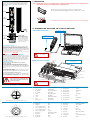
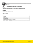
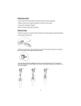
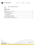
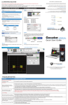
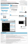
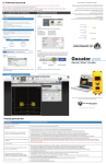
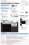
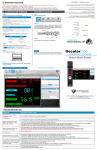
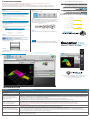
3. STARTING GOCATOR
©2015 LMI Technologies Inc. All rights reserved.
NOTE: Gocator must be connected to a host computer in order to launch the user interface and set up the sensor.
Gocator sensors are configured by connecting with a web browser.
The user interface supports FireFox 3.5+, Chrome 4.0+, and Internet Explorer 8.0+. (Use Firefox or Chrome for optimal
performance.) The Adobe Flash browser plugin version 10.0+ must be installed. Version 4.0 of the interface is shown here.
A. LAUNCHING THE INTERFACE
B. RUNNING GOCATOR
Step 1
Step 1
Change network setting on host computer
Select the Manage page.
In Windows 7
Phone:
[email protected]
Web:
www.lmi3D.com
192.168.1.10
255.255.255.0
Gateway
0.0.0.0
Step 2
Email:
IP Address
Subnet Mask
RECORD
SNAPSHOT
Worldwide
Disabled
North America
Default
DCHP
+1 604 636 1011
Fax:
+1 604 516 8368
REPLAY (off)
Gocator is shipped with the following default network
configuration
Setting
Phone:
•Open the Network Pane in System Preferences and select Ethernet.
•Set Configure to “Manually”.
•Enter IP Address “192.168.1.5” and Subnet Mask “255.255.255.0”, then
click Apply.
Europe
In Mac OS X 10.6
Step 2
Ensure that Replay mode is off (slider set to left) and that the
Laser Safety switch is enabled or the Laser Safety input is
high. Press the Start button in the toolbar to start the sensor
(a laser line should now be visible).
+31 45 850 7000
Fax:
+31 45 574 2500
•Open the Control Panel>Network and Sharing Center>Change Adapter
Settings.
•Right-click desired network connection, then click Properties.
•On the Networking tab, click Internet Protocol Version 4 (TCP/IPv4),
then click Properties.
•Select “Use the following IP address” option.
•Enter IP Address “192.168.1.5” and Subnet Mask “255.255.255.0”, then
click OK.
START
Step 3
Move target into the projected light pattern and measure!
Open a web browser and enter the sensor address
Step 3
NOTE
Select language of choice
Gocator sensors can also interface directly with HexSight.
Refer to the HexSight Quick Start Guide for more information.
3100
Quick Start Guide
Step 4
The Administrator password is initially blank. Press the Login
button to connect
An example of the user interface in use
Once connected to the Gocator, click the Help icon to
view the user manual or download the SDK
For the user manual, CAD drawings, firmware release notes, SDK,
and more, go to www.lmi3D.com/support/downloads
15198-1.4-Manual_Quickstart_Gocator-3100A-Series
TROUBLESHOOTING
PROBLEM
SUGGESTED RESOLUTION
Mechanical / Environmental
The sensor is warm.
• It is normal for a sensor to be warm when powered on.
Connection
When connecting with a web
browser, the sensor is not found
(page does not load).
• Verify the sensor power is on. This will be indicated by an illuminated POWER indicator light.
• Verify the Power & Ethernet cordset is connected to the Power/LAN connector and the Ethernet end’s RJ45 of the cordset is connected to the Ethernet switch.
• Verify that the client computer’s network settings are properly configured. Refer to the Connecting to a New Sensor section in the Gocator user manual or to
your computer’s documentation on configuring a network adapter.
• Download 14405-x.x.x.x_software_go2_tools.zip from the downloads area of LMI’s website at www.lmi3D.com.
Unzip and run the Sensor Discovery Tool [bin>win32>kDiscovery.exe] to verify that the sensor has the correct network settings.
When attempting to log in, the
password is not accepted.
• Download 14405-x.x.x.x_software_go2_tools.zip from from the downloads area of LMI’s website at www.lmi3D.com.
Unzip and run the Sensor Discovery Tool [bin>win32>kDiscovery.exe] to discover the sensor on the network and restore default settings.
NOTE: Using the Sensor Discovery tool will reset your configuration settings to default - these settings can be recovered from the backup
files if previously saved.
3D Data Acquisition
When the Play button is pressed,
the sensor does not emit LED light.
• Verify that the LED indicator light on the Gocator is illuminated, if not, the safety input signal is off.
• Refer to the Safety Input section in the Gocator user manual to determine the correct solution for your application.
• The exposure setting may be too low. Refer to the Exposure section in the Gocator User Manual for more information on configuring exposure time.
• Use the Snapshot button instead of the Start button to capture 3D point cloud data. If the LED light flashes when you use the Snapshot button, but not when
• you use the Start button, then the problem could be related to triggering.
The sensor CPU level is near 100%.
• Review the active measurements and eliminate any that are unnecessary measurements.
• Consider reducing the trigger speed.
• Consider reducing the data resolution.
GOCATOR OVERVIEW
Each Gocator 3100 model is designed with a unique Clearance
Distance (CD), Measurement Range (MR) and Field of View
(FOV). Refer to your User Manual for more information about
your model.
1. MOUNTING
NOTE: Mounting the Gocator is recommended prior to applying power. Ensure that a proper earth ground and
heat sink have been properly established prior to applying power.
Mount the sensor using four M5 x 0.8 screws of suitable length.
The recommended thread engagement into the housing is 8 - 10 mm.
Camera
Light
Emitter
Do not install the sensor near objects that might occlude a camera’s view of the light
Camera
Mounting
Holes
M5X0.8 10
Power/LAN
2. CONNECTING GOCATOR TO A HOST COMPUTER
Standalone System
Indicators Lights
When starting the Gocator,
the Power and the LED (if
safety is enabled) indicator
lights should be illuminated
if they are not, please refer
to the trouble shooting table
or your User Manual.
I/O
Connector
POWER: 24-48VDC @ 13W
SAFETY: +24-48VDC TO ENABLE
WIRE RICH I/O
AS REQUIRED BY APPLICATION
IN - ENCODER / TRIGGER
OUT - SERIAL / ANALOG / DIGITAL
GROUNDING GOCATOR
Gocator housings should be grounded to the earth and the
grounding shield of the Gocator I/O cordsets. Gocator
sensors have been designed to provide adequate grounding
through the use of M5 x 0.8 screws. Always check grounding
with a multi-meter to ensure electrical continuity between the
mounting frame and the Gocator connectors.
The frame or electrical cabinet that the Gocator is mounted to
must be connected to earth ground.
Always power down sensor
before removing cables
from the sensor
GROUNDING CORDSET (RECOMMENDED)
To minimize interference with other equipment, the Power &
Ethernet or the Power & Ethernet to Master cordset (depending on cordset used in system) can be grounded by terminating the cordset shield before the split. The most effective
grounding method is to use a 360-degree clamp. See User
Manual for instructions.
ELECTRICAL SAFETY
Multi-Sensor System
Power, Laser Safety, Trigger inputs,
and Encoder
GOCATOR
Minimize voltage potential between system ground
and sensor ground
Care should be taken to minimize the voltage potential
between system ground (ground reference for I/O signals)
and sensor ground. Use shielded cables with shield grounded
at both ends. Sensor housing should be connected to earth
ground.
Use a suitable power supply
The +24-48V power supply used with Gocator 3100 sensors
should be an isolated supply with inrush current protection.
MASTER 2400
Use care when handling powered devices
Wires connecting to the sensor should not be handled while
the sensor is powered. Doing so may cause electrical shock to
the user or damage to the equipment.
USER PC
Failure to adhere to the guidelines described
in this section may result in electrical shock
or equipment damage.
CAT5E ETHERNET CABLE
GOCATOR I/O CORDSET
Leave protective caps on any
connectors that are not used.
GIGABIT ETHERNET
SWITCH
GOCATOR POWER AND ETHERNET
TO MASTER CORDSET
Connector Pin Details
Gocator Power/LAN (to standalone and to Master)
10
12
5
Function
Cable Conductor Color
1
GND_24-48V
White/Orange & Black
1
GND_24-48V
Orange/Black
2
DC_24-48V
White/Green & Black
2
DC_24-48V
Green/Black
4
3
Safety-
White/Blue & Black
13
4
Safety+
Blue/Black
5
Sync+
White/Brown & Black
6
Sync-
Brown/Black
7
Ethernet MX1+
White/Orange
3
11
9
6
8
1
2
7
14
View: Looking into the connector on the sensor.
16
2
15
5
9
6
10
12
8
7
11
Function
Cable Conductor Color
8
Ethernet MX1-
Orange
9
Ethernet MX2+
White/Green
10
Ethernet MX2-
Green
11
Ethernet MX3-
White/Blue
12
Ethernet MX3+
Blue
13
Ethernet MX4+
White/Brown
14
Ethernet MX4-
Brown
Function
Cable Conductor Color
Function
Cable Conductor Color
1
Trigger_in+
Grey
11
Encoder_Z+
White/Green & Black
2
Trigger_in-
Pink
12
Encoder_Z-
Green / Black
3
Out_1+ (Digital Output 0)
Red
13
Serial_out+
White
4
Out_1- (Digital Output 0)
Blue
4
5
Out_2+ (Digital Output 1)
Tan
14
Serial_out-
Brown
14
6
Out_2- (Digital Output 1)
Orange
15
Reserved
Blue / Black
3
7
Encoder_A+
White/Brown & Black
16
Reserved
White / Blue & Black
13
8
Encoder_A-
Brown / Black
17
Analog_out+
Green
9
Encoder_B+
Black
18
Analog_out-
Yellow & Maroon/White
10
Encoder_B-
Violet
19
Reserved
Maroon
18
17
Pin
Pin
Gocator I/O
19
Pin
1
View: Looking into the connector on the sensor.
Pin