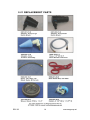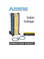
1
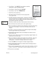
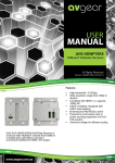
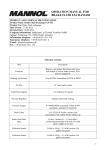
TABLE OF CONTENTS I. INTRODUCTION 2 II. SAFETY INFORMATION - Section 1.01: - Section 1.02: Important Safety Notice Important Safety Instructions 3 3 III. SYSTEM FEATURES & SPECIFICATIONS - Section 3.01: Features - Section 3.02: Dimensions & Technical Specs - Section 3.03: Machine Overview 4 4 5 IV. OPERATING PROCEDURES -Section 4.00: Fill New Tank -Section 4.01: 2 Line Exchange w/Reservoir -Section 4.02: 2 Line Exchange w/Expansion -Section 4.03: Vacuum Only w/Reservoir -Section 4.04: Vacuum Only w/Expansion -Section 4.05: Drain Waste Tank -Section 4.06: Drain New Tank 6 6-8 8-9 10-11 11-12 13 13 V. ADDITIONAL HELP -Section 5.01: Replacement Parts 14 WARRANTY INFORMATION 15 For Technical Assistance Toll Free: 877-906-1395 REV-03 1 www.aecgroup.net I. INTRODUCTION Congratulations on the purchase of your ADVANTAGE ENGINEERING COOLANT EXCHANGER system. The ADVANTAGE ENGINEERING COOLANT EXCHANGER is an easy to use system that allows fast, convenient, and efficient coolant exchanges. Using either one-line (vacuum only) or two-line (vacuum and pressure) methods, the ADVANTAGE ENGINEERING COOLANT EXCHANGER is versatile. The two-line approach pulls coolant by vacuum from the radiator while simultaneously pushing new coolant into the system. This approach will effectively replace most of the coolant in the system at a rate of up to one-gallon of coolant per minute. Designed for everyone, the ADVANTAGE ENGINEERING COOLANT EXCHANGER operates on pressurized air. Opaque tubes with gradient levels make it easy to see how much fluid has been removed and added to the system. II. SAFETY INFORMATION 1.01 Important Safety Notices For your safety, read this manual thoroughly before operating your ADVANTAGE ENGINEERING COOLANT EXCHANGER. This machine is intended for use by properly trained, skilled professional automotive technicians. The safety messages presented below and throughout this user’s manual are reminders to the operator to exercise care when using this unit. Before using the ADVANTAGE COOLANT EXCHANGER always refer to and follow the safety messages and applicable service procedures provided by the manufacturer of the vehicle being serviced. Read All Safety Instructions Read, understand and follow all safety messages and instructions in this manual. Safety messages in this section of the manual contain a signal word with a three-part message and in some instances an icon. REV-03 2 www.aecgroup.net 1.02 Important Safety Instructions Internal regulators are preset from the factory and should never be adjusted in the field unless by an authorized representative of AEC GROUP INC. Wear gloves when working near hot engine components. Do not touch hot exhaust sytems, manifolds, engines, radiators, etc. Keep the service hoses away from hot or moving parts. Hoses can split or burst causing fluid to be expelled. Do not use brake cleaner, WD-40 or other chemicals to clean cylinders. Rinse with fresh water. REV-03 3 www.aecgroup.net III. SYSTEM FEATURES & SPECIFICATIONS 3.01 Features Application Designed for one-man use Exchange coolant via pressure and vacuum 1 or 2 line approach Designed for use on both expansion and reservoir type systems Simultaneously removes old coolant (vacuum) while adding new coolant (pressure) on 2 line service Extends cooling system component life and system efficiency Functions Quickly and effectively exchanges coolant in approx. 10 minutes 2 lines for quick and thorough coolant exchange Large 4.25 U.S. gallon capacity for cars, SUV and trucks Opaque cylinders for monitoring operation and fluid volume Rugged, heavy-duty construction for long lasting service Delrin (non heat-conductive) adapters and quick disconnects Exchanger Features One (1) waste reservoir – approx. 4.25 U.S. gallon One (1) or two (2) new fluid reservoirs – approx. 4.25 U.S. gallon Delrin (non heat-conductive) adapters for most applications 8’ Steel reinforced external hoses 8” rigid rear wheels 3.5” swivel casters with brakes One (1) year limited warranty. 3.02 Dimensions & Technical Specifications Specifications CE2000 (Two Tube Model) Power Requirements: Air Pressure 70 min.-140 max. psi Weight: 90 lbs (41 kgs.) Shipping weight: 100 lbs (45.4 kgs.) Dimensions: 47.0” high (119 cm) 19.0” deep (48.3 cm) 20.0” wide (50.8 cm) REV-03 4 www.aecgroup.net REV-03 5 www.aecgroup.net IV. OPERATION PROCEDURES ADVANTAGE ENGINEERING COOLANT EXCHANGER Thank you for acquiring our Advantage Engineering two-line Coolant Exchanger. Please familiarize yourself with these instructions for filling, operating and draining before performing your first coolant exchange service. Please visit our website for informative videos on our products, www.aecgroup.net. You will need a 1/4” NPTM air plug for your air supply. You must have and maintain a “clean” air supply to the Coolant Exchanger between min. 70psi & max. 140psi. A simple in-line air/water separator is sufficient in most cases. 4.00 Filling Instructions – New Tank(s) The Advantage Engineering Coolant Exchanger can be filled by removing the caps from the top of the cylinder(s). Remove cap to new coolant tank. Fill with coolant and/or water. Each band on the coolant enclosure represents approximately 1 U.S. gallon. Note: Close cap until slightly snug. It is not necessary to tighten with a wrench. 4.01 Operating Instructions – 2 LINE SERVICE RESERVOIR (engine off, operating temperature) Reservoir system is a storage tank for the cooling system. This system will have a radiator cap. As the system heat increases, coolant expands and is pushed past the radiator cap into the reservoir. When the system cools down it is pulled back into the radiator keeping it at the proper level. 1. Connect air hose to rear of machine (70min.-140 max. psi). 2. Add a 50/50 mixture of new coolant and water to fill “new” tank (follow “Filling Instructions” 4.00). 3. Attach cone adapter to “WASTE” hose. Cone adapter valve should be closed. REV-03 6 www.aecgroup.net 4. Valve Position - Top “AIR ON” Valve positions on machine match those on top for “Exchange Coolant”. should 5. Valve Position - Waste Tank valve “VACUUM” 6. Valve Position - New Tank “PRESSURE ON” 7. Select Tank (3 tube model only) 8. Wait approximately 20 seconds until vacuum gauge reads 20” hg. (green zone). min. of 9. Evacuate coolant from overflow reservoir. Insert the 1/2” OD black extension hose into the end of the cone adapter and into the reservoir. Open valve to evacuate coolant. Close cone adapter valve when complete. Remove 1/2” OD black extension hose from cone adapter. 10. Carefully turn radiator cap slowly to release pressure before removing. 11. Pinch off all hoses from overflow reservoir with supplied clamps. 12. Place cone adapter into radiator fill neck, fitting tightly to seal and create vacuum. Open valve on cone adapter. Coolant will be evacuated (radiator hose will collapse). 13. Evacuate 2–4 quarts of old coolant from the radiator (enough to avoid spillage when the upper radiator hose is disconnected). 14. Close valve on cone adapter. Remove cone adapter from radiator neck and replace radiator cap. 15. Disconnect upper radiator hose and insert corresponding “stepped” adapter, into radiator hose, secure with clamp. 16. Place cone adapter into radiator (where upper hose was attached). Open cone adapter valve. The Coolant Exchanger will draw a vacuum on the engine’s cooling system. It is normal for the upper radiator hose to collapse. 17. Connect the NEW hose to the upper hose adapter (stepped adapter). 18. Observe old fluid being extracted from radiator and new fluid being forced into the engine displacing the old. 19. When new tank has approximately ½ gallon of new coolant remaining, turn Valve Position –Top “AIR OFF”. Allow system to equalize, gauges will return to zero. 20. Close valve on cone adapter. REV-03 7 www.aecgroup.net 21. Remove “WASTE” and “NEW” hoses from adapters. 22. Remove step adapter from radiator hose. Then simultaneously remove cone adapter while reconnecting radiator hose to radiator. 23. Remove caps from radiator and overflow reservoir tank. 24. Remove all pincher pliers and clamps installed for service. 25. Valve Position – Top “ AIR ON” 26. Top off cooling system and overflow reservoir using cone adapter connected to “NEW” hose filling both radiator and overflow reservoir to appropriate levels. Note: Do not create seal with cone adapter when filling. Replace radiator and overflow reservoir caps. 4.02 Operating Instructions - 2 LINE SERVICE EXPANSION TANK (engine off, operating temperature) Expansion tank systems are visually close to a reservoir system but are pressurized and will have multiple hoses connected to it. Typically this type does not have an opening on the radiator but is filled through the expansion tank. 1. Connect air hose to rear of machine (70min.-140 max. psi). 2. Add a 50/50 mixture of new coolant and water to fill “new” tank (follow “Filling Instructions” 4.00). 3. Attach cone adapter to “WASTE” hose. Cone adapter valve should closed. be 4. Valve Position - Top “AIR ON”. Valve positions on machine should match those on top for “Exchange Coolant”. 5. Valve Position - Waste Tank valve “VACUUM” 6. Valve Position - New Tank “PRESSURE ON” 7. Select Tank (3 tube model only) 8. Wait approximately 20 seconds until vacuum gauge reads min. of 20” hg. (green zone). 9. Carefully turn expansion cap slowly to release pressure before removing. REV-03 8 www.aecgroup.net 10. Evacuate coolant from expansion tank. Insert the appropriate length (7” or 9”) 9/16” OD clear extension hose into the end of the cone adapter and into the expansion tank. The clear hose should almost reach bottom of expansion tank. Cone adapter must fit tightly in opening to create vacuum. 11. Open valve to evacuate coolant. Evacuate 2–4 quarts of old coolant from the expansion tank (enough to avoid spillage when the upper radiator hose is disconnected). 12. Close cone adapter valve when complete. Remove 9/16” clear extension hose from cone adapter. 13. Pinch off all hoses from expansion tank, with supplied clamps and replace expansion tank cap. Note: This type system typically has multiple hoses. 14. Disconnect upper radiator hose and insert corresponding “stepped” adapter into radiator hose, securing with clamp. 15. Place cone adapter into radiator (where upper hose was attached). Open cone adapter valve. The Coolant Exchanger will draw a vacuum on the engine’s cooling system. It is normal for the upper radiator hose to collapse. 16. Connect the “NEW” hose to the upper hose adapter (stepped adapter). 17. Observe old fluid being extracted from radiator and new fluid being forced into the engine, displacing the old. 18. When new tank has approximately ½ gallon of new coolant remaining. Valve Position –Top “AIR OFF”. Allow system to equalize, gauges will return to zero. 19. Close valve on cone adapter. 20. Remove “WASTE” and “NEW” hoses from adapters. 21. Remove step adapter from radiator hose. Then simultaneously remove cone adapter while reconnecting radiator hose to radiator. 22. Remove all hose pincher pliers and clamps installed for service. 23. Connect cone adapter to “NEW” hose. An audible “click” should be heard confirming that the adapter is secure. 24. Valve Position – Top “ AIR ON” 25. Top off expansion tank using cone adapter connected to “NEW” hose filling expansion tank to appropriate level. Note: Do not create seal with cone adapter when filling expansion tank. REV-03 9 www.aecgroup.net 4.03 Operating Instructions – 1 LINE SERVICE RESERVOIR VACUUM ONLY Vacuum only service commonly called “suck and fill”. This service is done through the radiator cap or expansion tank opening without disconnecting hoses from radiator. Note: This service in most cases replaces less coolant than a “2 Line” service. 1. Connect air hose to rear of machine (70min.-140 max. psi). 2. Add a 50/50 mixture of new coolant and water to fill “NEW TANK” (follow “Filling Instructions” 4.00). 3. Attach cone adapter to “WASTE” hose. Cone adapter valve be closed. should 4. Valve Position – Top “AIR ON” 5. Valve Position – WASTE TANK “VACUUM” 6. Valve Position – NEW TANK “PRESSURE OFF” 7. Select Tank (3 tube model only) 8. Wait approximately 20 seconds until vacuum gauge reads 20” hg (min.). 9. Carefully turn radiator cap slowly to release pressure before removing. 10. Pinch off hose from radiator neck to overflow reservoir. 11. Evacuate the coolant overflow reservoir. Insert the 1/2” OD black extension hose into the end of the cone adapter and into the reservoir. Open valve to evacuate coolant. Close cone adapter valve when done. 12. Remove 1/2” OD black extension from cone adapter. Place cone adapter into radiator fill neck. Open valve on cone adapter. 13. Evacuate old coolant from the radiator. 14. Close valve on cone adapter, maintaining vacuum in coolant system. 15. Disconnect the “WASTE” hose from cone adapter, maintaining vacuum in coolant system. 16. Connect the “NEW” hose to the cone adapter. An audible “click” should be heard confirming that the adapter is secure. REV-03 10 www.aecgroup.net 17. Open cone adapter valve. Observe new fluid being drawn into the engine. 18. When the fill is complete, close valve on cone adapter. 19. Remove cone adapter and hose from radiator. 20. Valve Position - NEW TANK “PRESSURE ON”. Top off cooling system and overflow reservoir. Note: Do not create seal with cone adapter when filling. Close the cone adapter valve when complete. 21. Valve Position – Top “AIR OFF” 22. Replace radiator and overflow reservoir caps. Remove clamp(s) from radiator neck to overflow reservoir. 4.04 Operating Instructions - 1 LINE SERVICE EXPANSION TANK VACUUM ONLY Expansion tank systems are visually close to a reservoir system but are pressurized and will have multiple hoses connected to it. Typically this type does not have an opening on the radiator but is filled through the expansion tank. Note: This service in most cases replaces less coolant than a “2 Line” service. 1. Connect air hose to rear of machine (70min.-140 max. psi). 2. Add a 50/50 mixture of new coolant and water to fill “new” tank (follow “Filling Instructions” 4.00). 3. Attach cone adapter to “WASTE” hose. Cone adapter valve should be closed. 4. Valve Position - Top “AIR ON”. Valve positions on machine should match those on top for “Exchange Coolant”. 5. Valve Position - Waste Tank valve “VACUUM” 6. Valve Position - New Tank “PRESSURE OFF” 7. Select Tank (3 tube model only) 8. Wait approximately 20 seconds until vacuum gauge reads min. of 20” hg. (green zone). 9. Carefully turn expansion cap slowly to release pressure before removing. REV-03 11 www.aecgroup.net 10. Evacuate coolant from expansion tank. Insert the appropriate length (7” or 9”) 9/16” OD clear extension or ½” x 19” black hose w/ferrule into the end of the cone adapter and into the expansion tank. The extension hose should almost reach bottom of expansion tank or into intake hose at bottom of expansion tank. Note: Cone adapter must fit tightly in opening to create vacuum. 11. Evacuate old coolant from the coolant system. 12. When all coolant is evacuated close valve on cone adapter, maintaining vacuum in coolant system. 13. Disconnect the “WASTE” hose from cone adapter, maintaining vacuum in coolant system. 14. Connect the “NEW” hose to the cone adapter. An audible “click” should be heard confirming that the adapter is secure. 15. Open cone adapter valve. Observe new fluid being drawn into the engine. 16. When the fill is complete, close valve on cone adapter. 17. Remove cone adapter and Hose from expansion tank. 18. Valve Position - NEW TANK “PRESSURE ON” Top off expansion tank if needed. Close the cone adapter valve when complete. 19. Valve Position – Top “AIR OFF” For Technical Assistance Toll Free: 877-906-1395 REV-03 12 www.aecgroup.net 4.05 Drain Waste Tank Instructions 1. Attach the cone adapter to the “WASTE” hose. Cone adapter MUST BE “CLOSED” to prevent spillage. 2. Valve Position – Top “AIR ON” 3. Valve Position – WASTE TANK “PRESSURE” 4. Valve Position – NEW TANK “PRESSURE OFF” 5. Open cone adapter valve and drain waste tank into appropriate container. 4.06 Drain New Tank Instructions 1. Attach the cone adapter to the “NEW” hose. Cone adapter MUST BE “CLOSED” to prevent spillage. 2. Valve Position – Top “AIR ON” 3. Valve Position – WASTE TANK “VACUUM” 4. Valve Position – NEW TANK “PRESSURE ON” 5. Select Tank (3 tube model only) 6. Open cone adapter valve and drain new tank into appropriate container. REV-03 13 www.aecgroup.net REV-03 14 www.aecgroup.net LIMITED ONE (1) YEAR WARRANTY COOLANT EXCHANGER AEC GROUP INC. warrants only to the original Purchaser that under normal use, care and service, the Equipment (except as otherwise provided herein) shall be free from defects in material and workmanship for one year from the date of original invoice. External hoses, adapters and all other attachments, supplies and consumables (except as otherwise provided herein) are warranted for 90 calendar days from the date of original invoice. SELLER’S OBLIGATIONS UNDER THIS WARRANTY ARE LIMITED SOLELY TO THE REPAIR OR, AT SELLER’S OPTION, REPLACEMENT OF EQUIPMENT OR PARTS WHICH TO SELLER’S SATISFACTION ARE DETERMINED TO BE DEFECTIVE AND WHICH ARE NECESSARY, IN SELLER’S JUDGEMENT, TO RETURN THE EQUIPMENT TO GOOD OPERATING CONDITION. NO OTHER WARRANTIES EXPRESS OR IMPLIED OR STATUTORY, INCLUDING WITHOUT LIMITATION ANY IMPLIED WARRANTY OF MERCHANTABILITY OR FITNESS FOR A PARTICULAR PURPOSE, SHALL APPLY AND ALL SUCH WARRANTIES ARE HEREBY EXPRESSLY DISCLAIMED. This warranty does not cover (and separate charges for parts, labor and related expenses shall apply to) any damage to, malfunctioning, inoperability or improper operation of the Equipment caused by, resulting from or attributable to (A) abuse, misuse or tampering; (B) alteration, modification or adjustment of the Equipment by anyone other than Seller’s authorized representatives; (D) improper or negligent use, application, operation, care, cleaning, storage or handling; (E) fire, water, wind, lightning or other natural causes; (F) adverse environmental conditions, including, without limitations, excessive heat, moisture, corrosive elements, dust or other air contaminants, radio frequency interference, electric power failure power line voltages beyond those specified for the equipment, unusual physical, electrical or electromagnetic stress, and/or any other condition outside of Seller’s environmental specifications; (G) use of the Equipment in combination or connection with other equipment, attachments, supplies or consumables not manufactured or supplied by Seller; or (H) failure to comply with any applicable federal, state or local regulation. Repairs or replacements qualifying under this warranty will be performed on regular business days during Seller’s normal working hours within a reasonable time following Purchaser’s request. All requests for Warranty Service must be made during the stated Warranty period. This warranty is non-transferable. REV-03 15 www.aecgroup.net For Technical Assistance Toll Free: 877-906-1395 AEC GROUP INC. 3600 West Carriage Drive, Santa Ana, CA 92704 USA Ph: (877) 906-1395 / (714) 444-1395 Fax: (714) 444-1396 www.aecgroup.net REV-03 16 www.aecgroup.net