1
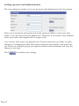
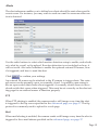
Network / IP Camera
User Manual
Preface
Congratulations on your purchase of this product. Read this manual carefully and
keep it in a safe place for future reference.
About this manual
This user manual has been designed to help you make the most of your IP camera
and its many features and functions. Information in this document has been carefully checked for accuracy; however, no guarantee is given to the correctness of the
contents. The information in this document is subject to change without notice.
Copyright
© Copyright 2005
This manual contains proprietary information, protected by copyright. All rights
reserved.
Table of Contents
Introduction
Key features............................................................................................................ 1
Package contents ................................................................................................... 2
Product views ........................................................................................................ 3
Indicators ................................................................................................................ 4
System requirements ............................................................................................ 4
Getting Started
Software installation ............................................................................................. 5
Hardware installation........................................................................................... 5
Assembling the stand....................................................................................... 5
Connecting to a network ................................................................................. 6
Connecting power ............................................................................................ 6
Enabling Active X .................................................................................................7
Initial configuration.............................................................................................. 8
Using an internet browser to connect to the IP camera................................... 9
Using and Configuring
Web page layout.................................................................................................. 10
Configuring the camera...................................................................................... 11
Configuring the image ................................................................................... 11
Setting up users and administrators............................................................ 12
Configuring network settings....................................................................... 13
Alert .................................................................................................................. 15
Advanced......................................................................................................... 16
Home ................................................................................................................ 17
The side menu bar............................................................................................... 17
Right click control ............................................................................................... 18
Image ................................................................................................................ 18
Record .............................................................................................................. 18
Zoom ................................................................................................................ 18
Motion detection............................................................................................. 18
Appendix
Specifications........................................................................................................ 19
Maintenance ......................................................................................................... 20
Glossary ................................................................................................................ 21
Introduction
This section covers unpacking your new IP camera, its key features, and basic
technical information about the product. Refer to later chapters for information on
setting up and configuring the product in more detail.
Key features
• 640x480 (VGA), 320x240 (CIF), 160x120 (QCIF) resolutions
• 307, 200 effective pixels
• Max frame rate 12 fps at VGA resolution
• 6 mm, F1.8 lens
• Configuration and viewing via standard internet browser
• Built-in microphone
• Motion detection feature
• E-mail and ftp alert features
• Automatic infrared night vision function
• External DI sensor input
Page 1
Package contents
The package should contain all the following. If anything is missing or appears
damaged, contact your dealer immediately.
IP camera module
Mounting bracket
RJ-45 cable
Mounting screws
AC power adaptor
Quick start guide
���������
��������
CD-ROM with manual and software
Page 2
Product views
Use the following illustrations to familiarize yourself with the camera and identify
each of the parts.
Front View
Lens
assembly
Light sensor
Night vision
IR LEDs
Night vision
IR LEDs
Microphone
Back View
LAN /
power
indicators
Reset button
RJ-45 LAN
Connector
DC-IN
socket
DI sensor
connector
Bottom View
Mounting
point
Page 3
Indicators
The following table shows what each of the LED indicators means.
LED
LAN
Power
Color
green
green
Description
network activity indicator
power indicator
System requirements
The system requires an Ethernet port and an IP address.
To view the IP camera images, each computer requires:
• Microsoft Windows 98, ME, NT4.0, 2000, or XP. Mac or Linux based machine.
• Microsoft Internet Explorer 5.x, or later.
Page 4
Getting Started
Read this section of the manual to learn how to set up your IP camera and use its
basic functions.
Software installation
You do not need to install any software for simply viewing images from the IP
camera, but you will need to use the supplied auto scan software to set the camera
up for the first time and find it on the network.
To install the auto scan software:
1. Insert the supplied CD-ROM into your CD-ROM drive.
2. If the installation does not start automatically, use a file explorer application
to execute the setup.exe file in the root folder on the CD-ROM.
3. Follow the on-screen instructions.
Hardware installation
Read this section to learn how to install the camera and connect to a network
Assembling the stand
Assemble the stand and fix it to the camera as
shown.
Use the three screws and plugs provided to fix the
stand bracket to a wall, or other convenient fixing
point.
The stand can be adjusted to allow the camera a
full 360º of rotation and a pan and tilt action .
Warning
The camera is not waterproof and should not be
mounted outside or in a position where it could
become wet.
Page 5
Connecting to a network
The IP camera can be connected to an Ethernet network, using the RJ-45 port, as
shown. Connect the camera to an Ethernet hub or switch using a standard cable.
You can also connect a computer directly to the camera using the supplied crossover cable.
Connecting power
Connect power to the IP camera as shown.
Warning
Use only the power adapter supplied with the camera. Using another adapter, not recommended by the manufacturer, may damage the camera and invalidate the warranty.
Page 6
Enabling Active X
Your browser must have Active X enabled to connect to the IP camera.
To enable Active X in your browser:
1. Open your internet browser.
2. Click on the tools menu at the top of the screen
and select Internet Options...
3. Select the security tab from the internet
options menu.
4. Click the
button and enable
all the Active X features in the list using
the radio buttons.
Page 7
Initial configuration
Read this section to learn how to configure and begin using the IP camera. A complete description of the features and functions can be found in the next chapter.
To install the camera on a network, you first need to give it an IP address. See your
network administrator to obtain an IP address suitable for your network, along
with a netmask, the gateway address, and HTML port.
To install an IP address:
1. Connect the IP camera to your network or host PC as described in “Connecting to a network” on page 6.
Note:
Connecting the camera to your network before you have configured an IP address
may cause problems such as address conflicts. To avoid these problems, connect
the camera to an isolated PC with a hub or cross-over cable to configure the network settings.
2. Start the IP Edit software. The following screen is displayed:
Cameras
discovered on
network
Exit
Update
Submit
Page 8
IP Camera
3. Click the Update button to scan for your IP camera.
4. When it appears in the window, click the name of your camera to highlight it.
5. Use the radio buttons to determine whether to connect to the camera using
DHCP, static IP address, or PPPoE. If you don’t know which of these options
to select, ask your network administrator for assistance.
6. Fill in all the required fields. Fields that are not required will be greyed-out.
7. Click the Submit button to update the camera with the new configuration.
When the above steps have been completed, you can double click the name of the
camera in the display window to connect to it using the default browser. Alternatively, you can connect to the camera by entering the IP address in the browser
address field.
Using an internet browser to connect to the IP camera
Read this section to learn how to use your Internet browser to connect to the IP
camera, view images, and hear audio output. Active X features must be enabled in
your browser to use the IP camera. See “Enabling Active X” on page 7.
To connect to the IP camera using an Internet browser:
1. Enter the IP address of the camera in the browser address field.
2. When the login screen appears, enter your username and password. The default username is admin, the default password is also admin.
Page 9
Using and Configuring
Read this chapter to learn how to operate the IP camera and take advantage of the
advanced features such as alerting, and ftp transfers.
Web page layout
Image
User
Network
Alert
Advanced
Use the menu bar at the top of the screen to access the six submenus:
• Image:
• User:
• Network:
• Alert:
• Advanced:
To adjust the image
To set up new admin or general users
To configure network settings
To configure alerts
To configure advanced parameters
Resolution and audio settings can be accessed from the side menu panel. Snapshots can also be taken of the screen image and either opened in a browser window, sent as e-mail, or transferred using ftp, using the side menu panel. Each
submenu and function is covered in detail in this section of the manual.
Page 10
Configuring the camera
Read this section of the manual to learn how to configure the IP camera using the
web browser interface.
Configuring the image
Use the image submenu to set the image resolution and quality. Using high resolution and quality will result in larger file sizes and therefore higher bandwidth.
You can also use the Image submenu to set the frequency of the mains power in
your area. This is to avoid problems with artificial lighting interfering with the
camera.
Use the radio buttons to set a value for resolution, quality and frequency. Click
to confirm your settings.
You can also set the resolution with the radio buttons in the side menu panel.
Page 11
Setting up users and administrators
The user submenu enables you to set up users and administrators for the camera.
Enter a new username and passwords in the required fields to create new user
names. You can only create one admin user. Therefore, if you enter a new administrator user name, the original will no longer work.
You can also only create one general user. General users have no ability to make
changes to configuration other than image resolution and quality, and audio output. However, multiple people can sign on with the same username and view the
camera at one time.
Click
Page 12
to confirm your settings.
Configuring network settings
The Network submenu enables you to configure all the network settings for the
camera.
Complete all the fields as required. You may not require all the fields. For instance,
you will not need to complete the static IP address fields if you are installing the
camera on a network that allocates addresses using DHCP.
Click
to confirm your settings.
Page 13
HTTP ports
The user can set up to two TCP ports for IP camera web servers. The deafult port
number is 80 (the standard web server port) the second port is user defined. If you
are not using port 80, you will need to enter the port number after the IP address
in the web browser window, to connect to the IP camera. If the camera IP address
was 10.0.1.216 and the port number was 88 for instance, you would enter the folllowing in the browser address field to connect to the camera:
DNS 1
Use the same value as PCs on your LAN. Normally, your ISP will provide this address.
DNS 2
This is optional. If entered, this DNS will be used if the DNS1 does not respond.
DNS
Domain name system , internet domain name and IP address mapping service.
DDNS
DDNS allows PPPoE or DHCP dynamic IP users to access the IP canmera using a
single domain name. The IP camera supports DDNS and meets the Dynamic Net
work Services, Inc standard.
Go to www.dyndns.org to register a domain name and obtain a username and
password. This username and password must be filled in on the network setting
page in the DDNS field. See “Configuring Network Settings” on page 13 for details.
When the IP address of the camera changes it will update its new address to DDNS
automatically and the camea can be contacted using a domain name instead of an
IP address.
Page 14
Alerts
The alert submenu enables you to define how alerts should be sent when specific
events occur. For instance, you may wish to send an e-mail to someone when motion is detected.
Use the radio buttons to select which motion detection setup to enable, and whether to alert by e-mail, or ftp upload. If motion detection is not switched on here, it
will not work. Also select whether to enable the optional external DI sensor, how
it’s triggered, and how to send the alert.
Click
to confirm your settings.
An external DI sensor can be attached to the IP camera to trigger alerts. The external sensor can be normally open, or normally closed. A normally open sensor is
like an open switch that closes when triggered. A normally closed sensor is like a
closed switch that opens when triggered. This must be set correctly on the alert setting page for an external sensor to function properly.
FTP
When FTP alerting is enabled, the camera sends a still image every time the alert
is triggered to the ftp server specified in the Advanced page, see page 17. The ftp
protocol is commonly used to upload to a web page.
Mail
When mail alerting is enabled, the camera sends a still image every time the alert is
triggered to the e-mail adress specified on the advanced page, see page 17.
Page 15
Advanced
Use the Advanced submenu to configure various advanced features of the camera.
You can use the advanced submenu to give the camera a name, set a SNTP (simple
network time protocol) clock source, set e-mail parameters for alerts, set ftp parameters, and upgrade firmware.
The settings on this page are critical and should not be changed without careful
planning. You may need to consult your network administrator for details about
your e-mail server or SNTP address.
You should not attempt to upgrade the firmware of the camera unless you have a
new version of firmware, provided by the manufacturer.
FTP Setting , use your FTP account and server to send still images, select your FTP
server type active or passive mode.
Mail Setting, use your email account to send still images
Page 16
Home
Click
at any time to return to the main camera image screen.
The side menu bar
Use the side menu bar to open a camera snapshot in a browser window, upload a
snapshot using ftp, or send a snapshot by e-mail.
Take snapshot and display in browser window
E-mail snapshot
ftp snapshot
Change resolution
Toggle audio on and off
Click
to open a browser window and display the current image.
Click
to send an e-mail of the current image to the e-mail recipient
defined in the Advanced settings.
Click
to upload the current camera image to the ftp location defined
in the Advanced settings.
Page 17
Use the radio buttons to select a frame rate, and click
to begin recording. The file will be saved in AVI format at the location defined in the Save as field.
Click
to end recording.
Zoom
Click zoom to open the zoom function. Use the mouse to drag a square that will be
zoom on the screen.
Motion detection
You can also use right click control to set two predefined motion detection areas,
and set motion detection levels for each area. Right click on the image to display
the drop down menu and select on the Motion detection option with the mouse. Motion detection must be enabled ont the alerts page for motion detection to operate.
See page 15.
Click 1 to set motion detection area 1. Use the mouse to draw a square on the
screen. Click and hold the left mouse button and drag the square across the area to
be monitored. Repeat the procedure to set area 2.
Click Motion Detect Set to set a sensitivity level for each area, 15 is most sensitive,
1 is least sensitive.
Enable motion detection on the alerts page, see “Alerts” on page 15 for details.
Page 18
Appendix
Specifications
• Sensor:
• Lens:
• CPU/encoder:
• Video compression:
• Audio compression:
• Image size (HxV):
• Frame rate:
• Protocol:
• Network:
• Status indicators:
• External DI:
• Night vision:
• Management:
• Alert:
• Snapshot:
• Record function:
• Clients:
• Supported OS:
• Supported browsers:
• EMC/safety:
• Power:
• Temperature:
• Humidity:
0.25-inch color CMOS 307,200 pixels (VGA) sensor
6 mm, F1.8, board lens
SOC/JPEG encoder chip
M-JPEG
ADPCM 8 kbps
640x480 (VGA), 320x240 (CIF), 160x120 (QCIF)
Up to 12 fps (VGA), 25fps (CIF)
TCP/IP, ARP, ICMP, HTTP, SMTP, FTP, DHCP,
DNS, DDNS, NTP, PPPoE
Ethernet 10Base-TX/10Base-T (RJ-45)
Power and LAN LEDs
1 x external interface
6 x IR LEDs (automatic)
2 layer guest/administrator management
Definable alerts by FTP or e-mail
Automatic or manual, sent by FTP or e-mail
Manual (AVI Microsoft DirectX8.1, VGA card
32-bit true color
Up to four
Microsoft Windows 98/ME/2000/XP/2003
Microsoft Internet Explorer 5.x or later
FCC/CE
DC 5V 2A
Operating 0-50ºC, storage -20ºC-70ºC
20% - 80%
Page 19
Maintenance
This product has no user serviceable parts inside and removal of the case should
not be attempted except by qualified service personnel.
Only use a clean cloth, slightly dampened with water to clean this camera. Do not
use spirit cleaners or solvents as this may damage the plastic case and lens parts.
Use a soft, dry cloth to clean the lens when required.
Do not install this camera in an environment where it is likely to be exposed to
dust, high humidity, high temperatures, or rain.
Do not install this equipment in an enclosed space with no ventilation. The camera
is likely to become warm during normal use and ventilation is required to maintain
a sufficiently low operating temperature. If the camera is mounted in an enclosed
space, it may overheat and may be permanently damaged.
If the camera begins to function badly or stops working, and routine maintenance
procedures described above do not solve the problem, contact your dealer and arrange for a service engineer to inspect the camera.
Page 20
Glossary
Alert:
An alert can be in the form of an e-mail or an ftp
upload of an image, that occurs when a sensor is
triggered, or motion is detected.
AVI:
Audio Video Interleaved. A Windows multimedia
video format from Microsoft.
CIF:
Common Interface Format. A standard video
resolution format used in video conferencing. CIF
resolution is 352x288 and bit rate is 36.5 Mbps (at
30 fps)
DHCP:
Dynamic Host Configuration Protocol. A system
by which each piece of equipment on a network is
allocated an address IP dynamically.
DI sensor:
The DI sensor input allows you to connect an
external sensor or switch to the camera that may
be used to trigger an alert. The DI sensor input can
be set to normally open (switch closing causes an
alert) or normally closed (switch opening causes an
alert.
Ethernet:
The most widely used local area network (LAN)
access method, defined by the IEEE as the 802.3
standard.
FTP:
File Transfer Protocol. A standard protocol designed for transferring files over a TCP/IP network.
IP:
Internet Protocol. The network layer protocol in
the TCP/IP communications protocol suite (the
“IP” in TCP/IP). IP contains a network address
and allows messages to be routed to a different
network or subnet.
LED:
Light Emitting Diode. A semiconductor device that
emits light when a voltage is applied.
Motion detection:
Camera function that causes an alert to be triggered when movement is detected in the field of
view.
Page 21
PPPoE:
Point to Point Protocol over Ethernet: A standard
that incorporates PPP protocol, widely used for
dial-up Internet connections, into a cable modem
connection that uses Ethernet as its transport to the
carrier’s facilities.
Protocol:
Standards governing the transmission and reception of data.
QCIF:
Quarter CIF. 176 x 144 resolution, 9.1 Mbps (at 30
fps).
Resolution:
Screen, resolution is expressed as a matrix of dots.
For example, the VGA resolution of 640x480 means
640 dots (pixels) across each of the 480 lines.
RJ-45:
Registered Jack 45. RJ-45 type connections are used
in Ethernet devices.
SNTP:
Simple Network Time Protocol. A protocol that
allows devices to update internal clocks using a
standard source available on a network.
Static IP address:
A static IP address that is assigned manually and
never changes.
TCP/IP:
Transmission Control Protocol/Internet Protocol.
A communications protocol developed under contract from the U.S.
VGA:
Video Graphic Array. The video display standard
for the PC.
Page 22