1
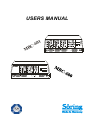
USERS MANUAL
MB
C-
5
5
4
3
2
5
5
5
4
4
4
3
3
3
2
2
1
2
1
1
F
MB C 6 0 1
BIPO
COAG
4
1
1
0
6
BIPO
Cut
MONO
COAG2
MONO
COAG1
1
MONO
COAG
MONO
CUT
MONO
CUT
3
2
1
F
MB C 6 0 0
Sör ing
Sicherheit
Safety
2
Söring
BIPO
Coag
Sicherheit
Safety
27/04/04
©
Söring
Users manual RF-units
Söring Inc
5009 Martin Luther King Jr. Freeway,
Fort Worth,
TX 76119
Tel: 001-817-457-2200
Fax: 001-817-547-2201
Söring GmbH
Medizintechnik
Justus von Liebig Ring 10
25451 Quickborn
Tel: (+) 49 (0)4106-6100-0
Fax: (+) 49 (0)4106-6100-10
E-mail: [email protected]
E-mail: [email protected]
BH-MBC-USA 04/2004
03-092 R3
1
not valid for MBC600
-2-
27/04/04
©
Söring
Users manual RF-units
Contents
1. Introduction ................................................................................................................. 5
2. Important notes regarding the operation of RF Surgery units ......................... 6
2.1. Operating of RF Surgery Equipment ................................................................................................6
2.2. User instructions ...................................................................................................................................6
2.3. Prescribed safety checks ....................................................................................................................6
2.4. Medical Product Log Book ..................................................................................................................6
2.5.How to keep the instruction manual and the medical product log book .................................7
2.6. Accident and damage report ..............................................................................................................7
2.7 Modifications and repairs .....................................................................................................................7
3. Physiological and physical fundamentals of RF Surgery .................................. 8
3.1. Heating effect of RF currents in biological tissue ........................................................................8
3.1.1 Reaction of biological tissue to local overheating ...........................................................................9
3.2 Methods of RF Surgery and electrical Signal Shapes.................................................................12
3.2.1 Cutting ...................................................................................................................................................12
3.2.2. Coagulation .........................................................................................................................................13
3.2.3. Electrodessication ..............................................................................................................................13
3.2.5. Bipolar application technique ...........................................................................................................14
3.2.5.1 Bipolar Automatic ......................................................................................................................................... 14
4. Patient safety ............................................................................................................. 15
4.1. Patient placement ................................................................................................................................15
4.2. Attachment of patient electrode ......................................................................................................15
4.4. Current carrying cables .....................................................................................................................18
4.5. Dangers from inflammable and explosive media. .......................................................................19
4.6 Instructions for special applications...............................................................................................19
Arrangement of Switches, Sockets and displays of MBC 601.........................................................20
Arrangement of Switches, Sockets and displays of MBC 600.........................................................21
5.1. Description of controls and indicators ..........................................................................................22
5.1.1 Description of the Safety Equipment ................................................................................................27
5.2 Putting the equipment into operation .............................................................................................28
5.2.1 Description of operational facilities ..................................................................................................28
5.2.2 Preparation of equipment ...................................................................................................................28
5.2.3 Switching on the equipment...............................................................................................................28
5.2.4. Adjustment of function fields ............................................................................................................29
6. Accessories (extracts) ............................................................................................. 30
7. Cleaning, maintenance, disinfection and sterilization ..................................... 31
8. Technical Data ........................................................................................................... 32
9. Technical safety checks .......................................................................................... 35
1
not valid for MBC600
-3-
27/04/04
©
Söring
Users manual RF-units
9.1 Intervals...................................................................................................................................................35
9.2 Extent .......................................................................................................................................................35
9.3. Description of special checks ..........................................................................................................35
9.3.1. Check of controls and indicators .....................................................................................................35
9.3.2. Check of handpieces and footswitches ..........................................................................................35
9.3.3. Check of RF generators and safety devices ..................................................................................36
9.3.4. Power measurement ..........................................................................................................................36
9.3.5. Current Leakage test .........................................................................................................................36
9.3.6. Test of handpiece allocation relay...................................................................................................36
9.3.7. Test of patient electrode recognition ..............................................................................................36
Remarks .......................................................................................................................... 37
1
not valid for MBC600
-4-
27/04/04
©
Söring
Users manual RF-units
1. Introduction
This operating manual describes the function and handling of the Radio Frequency Surgery
Equipment MBC. The manual serves as an instruction reference and should be read thoroughly
before operating the equipment. Only then can the correct handling of the equipment be assured.
In case of incorrect handling no liability will be taken on by the manufacturer.
MBC's are RF surgery equipment conforming to DIN IEC 601 part 1, respectively EN60601-1
utilized only for rooms for medical use. Every important function is controlled and supervised by a
microprocessor.
The MBC units, in MONOPOLAR MODE, are meant for the use in general surgery and
gastroenterology. In MONOPOLAR MODE, operations on the heart, eyes and in the brain
(neurosurgery) are not admissible!!!
This equipment has not been developed for continual operation (constant power supply for a
longer period). The period for use fulfills the demands for operation of the EN60601-2-2 (10s load,
30s break).
This RF Surgery unit meets the requirements of the (EMC) guideline 93/42/EWG of the European
Community and is therefore labeled with the
0123
sign!
Before starting operation the appropriate handpieces must always be checked for external
damage.
The Söring Company only accepts liability if accessories from the Accessories Order List
were used!!!
At the end of the normal life cycle of the unit it should be taken to either a legitimate electronics
disposal site or to the Söring Company.
Symbols Used
F
!
Patient electrode
(when RF applied patient
electrode- electrode insulated against earth)
Defibrillator save
Attention!, see also covering
documents
Monopolar Cutting & Coagulation
Off (separation from main power
supply)
Bipolar Cutting 1 and Coagulation
On (connection to main power supply)
Potential equation pin
Attention high voltage
type CF
CE label acc. To 93/42/EWG
0123
1
not valid for MBC600
-5-
27/04/04
©
Söring
Users manual RF-units
2. Important notes regarding the operation of RF Surgery units
During operation of RF surgery equipment disturbances of other electronic devices
may occur due to generated interfering signals.
2.1. Operating of RF Surgery Equipment
The user is only allowed to operate such RF Surgery Equipment after the manufacturer or the
distributor has:
1. Checked the equipment for faultless function at the location of operation and
2. Introduced the person responsible to the operation of equipment according to the instruction
manual.
2.2. User instructions
RF Surgery equipment is only to be operated by persons, who have been introduced to the
correct use of the equipment according to the instruction manual. Only people with sufficient
knowledge of how to handle the equipment and practical experience are allowed to instruct
others.
If such instruments are combined with additional equipment, the instruction of the operating
personnel must be extended to the combination and its special functions.
2.3. Prescribed safety checks
The user of the RF Surgery unit must carry out the prescribed safety checks within the period
stipulated and to the extent required. The extent and the periods for safety checks for RF
equipment must be performed according to manufacturer's recommendations regarding extent
and periods of inspections during servicing.
Safety checks of the technical protocols must be assigned only to those who have the
appropriate education, the knowledge, and the experience gained during their practical work
enabling them to carry out those checks accordingly. The safety check should be performed in
a distraction free environment. If failures are found during safety checks, which may endanger
patients, staff or third parties, the technician must immediately inform the authority responsible
for the use of the instrumentation.
2.4. Medical Product Log Book
The supervising operator of RF Surgery units must keep a medical product log book. Other
documentation is equivalent to the medical product log book, as long as it fulfills the
requirements of the medical product log book to the same extent and is available for the user
at any time.
The following entries are to be made in the medical product log book
1. Date and time of the function test before operating the equipment for the first time.
2. Date and time of instruction, as well as the names of the instructed persons.
3. Date and time of performing required safety checks and maintenance as well as the name of
the person or the company performing these checks.
4. Date, time, kind, and consequences of failures and of re-occurring similar operation
mistakes.
A copy of the CE certificate must be kept with the medical product log book.
1
not valid for MBC600
-6-
27/04/04
©
Söring
Users manual RF-units
2.5.How to keep the instruction manual and the medical product log book
Instruction manuals and equipment books for RF surgery equipment must be kept, so that they
are always accessible to persons commissioned to use the equipment.
The responsible authority may ask to look at these books at any time.
2.6. Accident and damage report
Function failures or breakdowns of medical equipment causing bodily injury must be reported
immediately to the authority responsible.
The hospital must report the incident to the FDA and include all of the pertinent information as
required by that agency. Suggested information to be gathered by the hospital includes the
following:
1.
What caused this event?
2.
Was the equipment in proper operating condition
3. If repaired, does danger no longer exist.
4. Has new knowledge been gained which will make other or additional safety provisions
necessary?
2.7 Modifications and repairs
Modifications and repairs must not reduce the safety of the equipment and accessories for the
patient, user, or the environment. Therefore, modifications and repairs to this equipment must
only be carried out by the manufacturer or by persons explicitly authorized by Söring. If nonauthorized persons perform unqualified modifications and repairs to the equipment or
accessories, the manufacturer will not accept liability. Furthermore in this case the warranty
expires.
1
not valid for MBC600
-7-
27/04/04
©
Söring
Users manual RF-units
3. Physiological and physical fundamentals of RF Surgery
Thermocautery as an aid to mechanical operation techniques began many years ago with the
application of heated metal tools to wounds to control bleeding. The technique was found to be
very effective. Later the use of electrical power to effect electro-cauterization and cutting of
tissue was the next logical step. RF Surgery is the use of high frequency alternating electrical
current (frequency higher then 300 kHz) with the purpose of alteration or destruction of cells and
for cutting tissue. It is used for tissue removal and cauterization in connection with mechanical
operation techniques. The tissue cauterization and cutting effects are accomplished by a
combination of heating through the electrical resistance offered by the biological tissue and
through the heating of the electrode.
3.1. Heating effect of RF currents in biological tissue
The heat production is mainly a result of the fact that biological tissue acts as an electrical
resistor for frequencies normally used during RF surgery and that as an electrical resistor
biological tissue heats up when electric currents flow through.
The amount of heat developed is therefore dependent on the current and the resistance of the
conductor (the biological tissue) put up by the patient.
From the electrical point of view the patient is the conductor. The material of the conductor and its
geometrical shape influences the resistance of this conductor. In this connection a comparison of
specific resistance of metallic conductors and biological tissue is of interest. Table 3.1 clearly
shows that the specific resistance of metals is much smaller than that of biological tissue. As a
result, in a closed current loop of metallic conductors and biological tissue of equal cross
sectional area the biological tissue heats up significantly more. As can be seen in the table below,
different biological tissue types offer a wide range of electrical resistance and thus are affected
differently by the applied RF signal. The MBC internal circuitry automatically senses the resistivity
and adjusts the RF signal accordingly for the best results.
Biological Tissue
[ Ω . cm]
Metal
(in the range 0.3 to 1 MHz)
[ Ω cm]
.
blood
160
silver
0,0000016
muscle, kidney, heart
200
copper
0,0000017
liver, spleen
300
gold
0,0000022
lung
1000
aluminum
0,0000029
fat
3300
Table 3.1: Comparison of specific resistance of metals and biological tissue
The desired thermal effect should be accomplished within a small area in front of the active
electrode. Conditions for RF heating are areas with small cross-sectional area and low electrical
conductivity.
The actual temperature at the contact area between the active electrode and tissue results from
the energy balance. The energy supplied is influenced by:
-Current per area (dependent on specific resistance of the tissue and the shape of the
electrode).
-Effective time (the time that the RF current acts on the tissue area as determined by the
electrode type and velocity of the electrode over the tissue).
-Current shape (full power, alternation of power, or changing power levels)
The conducted heat is influenced by:
-The condition of the tissue, particularly at any given moment of the application cycle because
the local thermal conductivity changes as tissues are destroyed.
-Temperature, because additional energy is needed for vaporization of tissue fluid.
1
not valid for MBC600
-8-
27/04/04
©
Söring
Users manual RF-units
HF-Generator
RF-generator
Aktive-Elektrode
active electrode
biologisches Gewebe
biological tissue
Neutral-Elektrode
Patient electrode
Fig 3.1. Shows the principle of RF Surgery
3.1.1 Reaction of biological tissue to local overheating
If RF voltage (continuous sine signal) reaches a certain upper limit, an arc will occur at the
contact zone of the active electrode to the tissue. This leads to a quick heating of the intercellular
fluid. This vaporization of the intercellular fluid results in a bursting of the cells and the tissue
looses its cohesion i.e., the electrode cuts.
Lower RF voltages (below 150v eff ) lead to a slower heating of the tissue, resulting in coagulation
with no tissue separation.
Short RF impulses with high voltage lead to a build-up of sparks together with a strong surface
coagulation.
1
not valid for MBC600
-9-
27/04/04
©
Söring
Users manual RF-units
active electrode
horny layer
papilliary body
subcutaneous fatty tissue
musculature with connective
tissue
vessel
bone
Fig 3.2
Schematic representation of a melt-cut: Depending on the value of resistance of the
different effected tissue the coagulation seam (the heat damage) is more or less
widespread; broader at the horny layer than in the papillary body or the subcutis, even
wider in the fatty tissue. In the musculature the heating effect melts deeper into the gaps of
the connective tissue. Within a cut vessel the blood retracts and the intima is damaged
from the different wall layers over a large area. In bones, the heating effect spreads along
both sides of the periosteum and spreads only slowly deeper below the tip of the electrode.
If, however, the heat developed is extended to a larger area due to a larger contact surface
between active electrode and tissue, boiling of the tissue fluids occurs together with widespread
albumin coagulation. Depending on the used current intensity either depth coagulation (see Fig.
3.3) or a surface coagulation (see Fig. 3.4) with eschar generation is achieved. Due to bad
thermal conductivity of eschar, heat transfer, especially into the depth, is prevented by eschar
formation.
1
not valid for MBC600
-10-
27/04/04
©
Söring
Users manual RF-units
active electrode
coagulated tissue
Fig. 3.3
Schematic representation of electro-coagulation on a homogenous tissue: The boiling extends to
a depth somewhat larger than the diameter of the electrode. It is strongest underneath the
electrode. At the surface it also extends to the surroundings of the electrode (rim effect).
generated eschar
active electrode
coagulated tissue
Fig. 3.4
Schematic representation of electro-coagulation with generated eschar: In this case the current
value used for electro-coagulation is too high. Close to the electrode a coagulation of tissue is
initiated so rapidly that eschar is created, the isolating effect of which prevents a deeper
electro-coagulation. Due to eschar the electrode sticks to the tissue.
1
not valid for MBC600
-11-
27/04/04
©
Söring
Users manual RF-units
3.2 Methods of RF Surgery and electrical Signal Shapes
Cutting and coagulation modes of RF surgery depend in part on the shape of the sine wave of the
electrical current. The frequency is remains around the 350 kHz range but the current amplitude
(power) is changed to meet the surgical demands. A cutting current is a continuous sine wave.
The amplitude is varied to accommodate the tissues being cut as each tissue type has a different
electrical resistance. A coagulating current has a diminishing sine wave form repeated over
intervals of time (parts of a second) and at varying sequence frequencies to achieve selected
levels of coagulation. In the initial phase of a coagulation event the amplitude of the current is
high and then falls to zero or almost so. If such a current could be heard it might resemble the
sound of a ringing bell. See Figure ZZ.
3.2.1 Cutting
The cutting effect is based on the principle of cellular rupture. This is accomplished by a rapid and
locally limited temperature rise causing an explosion-like vaporization of intra and extra cellular
fluids, which ruptures cells and fractures cell connections. Under ideal conditions no coagulation
occurs at the cut and the surfaces of the cut do not show the typical light color of a coagulation
seam.
Principle of cell destruction
The shape of the electrode influences the cutting action and the kind of cut in electrotomy.
Basically, cutting electrodes should have a tissue contact area as small as possible in order to
obtain a high current density within a narrow space.
Loop or Ribbon Electrode
Knife or Lancet Electrode
Needle or Wire Electrode
Fig 3.5 Shapes of electrodes
Needle or wire electrodes are particularly useful for fine cuts where no or only minor coagulation
is wanted. They present a very small tissue contact area allowing a high current density needed
for fine cuts. With higher power the electrode will overheat and tissue will stick to it.
Knife or lancet electrodes resemble conventional scalpels with respect to their geometrical shape.
The cutting action, however, is based on the above-mentioned principles and not on mechanical
action. The leading edge of a knife has a small contact area where high current density can be
produced for a fine cut, whereas, the broad sides of these electrodes achieve coagulation along
the cut surfaces. Due to the relatively larger surface, compared with the needle electrode, more
RF power is required. However the heating of these electrodes is lower due to their higher thermal
capacity.
Loop and ribbon electrodes are mainly used for the cutting tissue by in slicing. A major application
of this so called “hollow-cut“ is the TUR (Transurethral Resection) in urology. Further parameters
which influence the quality of the cut are the cutting velocity, the condition of the tissue and the
shape of the current.
1
not valid for MBC600
-12-
27/04/04
©
smooth
cut
Söring
Cut, rich of
coagulation
Users manual RF-units
Cut with eschar
Fig. 3.6
The smooth cut is largely comparable to the cut with a conventional scalpel, i.e. the cutting
surfaces are only slightly colored. This cutting mode is achieved with unmodulated RF-current and
by carrying-out the cut quickly.
A reduction of cutting speed gives a more coagulated cut even to the point of eschar with enough
speed reduction. The same result is achieved when using a pulse modulated RF current with the
same average power.
The power necessary for performing a RF cut depends on the shape of the electrode, type of
tissue and its resistance. If the power is too low, no cell rupture takes place and the tissue sticks
to the electrode. If the applied power is too high, spark discharges between electrode and tissue
are possible which causes carbonization of the cut surfaces.
3.2.2. Coagulation
For coagulation the tissue is heated more or less to such a degree that no cell rupture occurs.
The temperature for coagulation is above 50°C. This temperature leads to a coagulation of the
intra- and extra-cellular albumin (boiling of tissue). Perforated blood vessels contract so far that
the vessel is totally closed and no blood flows out. In order to obtain this effect, the electric
current must heat the tissue at a sufficiently slow speed so that the intra- and extra-cellular fluids
are vaporized without destroying the cell membranes. By this loss of fluid the cells contract and
the cell membranes are welded together.
This kind of coagulation is often called contact coagulation because the electrodes (shapes are
balls or plates) are brought into direct contact with the tissue. A supply of RF current causes a
light coloring of the tissue and a flow out of tissue fluid due to coagulation of cellular albumin.
3.2.3. Electrodessication
Electrodessication is a special mode of coagulation and is nowadays called Spray coagulation. By
means of a very high RF voltage, sparks or arcs between electrode and tissue surface are
1
not valid for MBC600
-13-
27/04/04
©
Söring
Users manual RF-units
generated and no direct contact is necessary. The spark over causes an extreme temperature rise
in the tissue areas close to the surface and destroys them (surface coagulation, eschar,
carbonization). Electrodes with a small area like small ball or needle electrodes are used.
The necessary high voltage with moderate RF power is reached by high pulse modulation. Peak
voltages up to 9kv pp are obtained by this method.
Spray coagulation is mainly used for a quick and widespread coagulation of tissue e.g. with
seeping hemorrhage. It should be noted that the frequently generated eschar causes bad healing
and after-bleeding.
3.2.5. Bipolar application technique
With bipolar application the RF current does not flow through the body of the patient but directly to
a second adjacent electrode of the surgical instrument (e.g. a tweezers leg). The advantage is
that the RF current only flows in an area where the surgical effect is wanted so that damage to the
surrounding tissue is largely avoided. Further advantages are the low power requirement and a
low disturbance effect (e.g. on measurement equipment). Fig. 3.8 shows a schematic
representation of bipolar application technique.
Isolation
Insulation
Isolierter
Pinzettenschenkel
Insulated Tweezers’ leg
Pinzettenspitze als
„Aktivelektrode“
Tweezers’ Tip as
„Active electrode“
Pinzettenspitze als
„Neutralelektrode“
Tweezers’ Tip as
„Patient electrode“
Fig. 3.8
This equipment provides the application techniques bipolar cutting 1 and bipolar
coagulation. As described in the previous chapters 3.2.1 and 3.2.2 a continuous
signal is also used for bipolar cutting. The coagulation occurs with a lower RF
voltage.
3.2.5.1 Bipolar Automatic
When the automatic function of bipolar been selected, the equipment switches on and off automatically for coagulation of tissue as soon as a sufficient tissue contact between the tweezers
legs has been recognized by resistance measurement. If required the system can be switched off,
so that the bipolar instruments can be activated by the footswitch. (see also chap. 5.1. point 7)
!
ATTENTION: Do not use Bipolar-Automatic-Mode (14) together with TissueLink Bipolar fluid
supported instruments. The irrigation fluid could disturb the recognition of the automatic function!!!
TissueLink fluid supported instruments have to be used only without activated bipolar automatic!
1
not valid for MBC600
-14-
27/04/04
©
Söring
Users manual RF-units
4. Patient safety
The power output should be reduced to a value as small as possible in order to
obtain maximum patient safety with the application. Apparent low output of the RF
surgical equipment to function correctly at the normal operating settings may
indicate faulty application of the patient electrode and its contact in its connections.
4.1. Patient placement
With applications of RF surgery equipment any contact of the patient with grounded metal parts
has to be carefully avoided. In order to ensure this, the following points must be observed
-
The patient shall not touch any piece of metal (i.e. OR table or any other metal parts). If
necessary, insulating arm or leg cuffs must be put on.
-
Conductive respirator hoses must not lay in contact with the patient.
-
The patient must not be laid down on moist sheets.
-
Excretions of the body such as perspiration, secretions, blood and so on, liquids put on
for cleaning purposes, or applied liquids like infusions and so on, must not soak through
the dry sheets. If necessary, it must be possible to suck it off immediately and
thoroughly in order to avoid the gathering of liquid beneath the patient.
-
Urine secretions must be drained via catheter.
-
Areas with strong secretion of perspiration, extremities lying close to the body or areas
where skin touches skin must be kept dry by sheet covers.
-
Anesthesia must be adjusted so that strong secretion of perspiration will be avoided.
Liquids of any kind must not be sprayed, spilled or used in ample quantities in order to
avoid its collection underneath the patient.
4.2. Attachment of patient electrode
This RF surgery equipment is provided with a patient electrode monitoring, which
checks the correct attachment of the patient electrode by measuring the transfer
resistance between the patient electrode and the patient tissue. For this
measurement the use of a split patient electrode is necessary. Although the use of an
undivided patient electrode is possible the manufacturer does not recommend it.
In order to apply the patient electrode carefully and safely to the patient the following shall be
observed:
-
If an undivided patient electrode is used the monitoring circuit only checks the
connection between patient electrode and equipment. However no monitoring takes
place if the patient electrode is connected to the equipment but not attached to the
patient. It is the responsibility of the OR staff to check the reliable attachment of the
electrode to the patient.
-
The patient electrode must be applied to the patient with its full surface in order to
achieve an even contact. Resting on bone projections must be avoided.
-
Furthermore any metal parts inside the body (i.e., bone-nail, endo-prosthesis, bone
plates, screws, etc.) must be considered as they may influence the current supply.
-
All external metal parts like rings, necklaces, bracelets, body piercing jewelry, etc. must
be removed.
-
1
The patient electrode must be attached so that the current paths between active and
patient electrode are as short as possible and directed alongside or diagonal to the
not valid for MBC600
-15-
27/04/04
©
Söring
Users manual RF-units
body, but under no circumstances at the thorax, because in this case the heart would
be located in the direct current path.
Fig. 4.1.Suggested placement of conventional patient electrodes and relevant operation fields.
-
Permanent electrodes must be carefully secured with a flexible bandage or with elastic
bands. Wet towels, paste for electrodes, and so on are not to be put underneath. On the
other hand paste may be used with adhesive disposable electrodes, if drying out of the
paste is avoided. To insulate the patient electrode also against its surroundings it is to be
wrapped with a bandage after setting.
Fig. 4.2.
1
Correct fastening
-
When using self-adhesive disposable patient electrodes building-up of blisters beneath
the electrode may occur due to incorrect handling, wrong electrode paste, etc. Thereby
the contact surface is reduced and burns are possible.
-
The contact surface for the patient electrode has to be cleaned, degreased, and freed
from strong growth of hair if necessary in order to obtain a low transfer resistance.
-
Alcohol should not be used for skin cleaning because it dries out the skin and causes
increased transfer resistance at the contact area of the patient electrode.
-
The contact area of the patient electrode should be moistened by carefully rubbing the
skin with a salt solution in order to obtain a good conductivity. Spraying should be
avoided because in this case salt solution could get underneath the patient.
not valid for MBC600
-16-
27/04/04
©
Söring
Users manual RF-units
Fig 4.3 Moistening of body parts for fastening of patient electrode
-
According to manufacturer’s specification the patient electrode must have a clean
surface free of corrosion and oxides in order to keep the transfer resistance as small as
possible.
-
Furthermore the surface area of the patient electrode must be sufficiently large so that
no unacceptable heat will develop.
-
In case of insufficient blood circulation the skin shall be massaged or brushed at the
contact area before applying the patient electrode. It should be mentioned that for long
lasting operations disturbed blood supply around the patient electrode might come up
again which leads to an increased transfer resistance.
-
If the transfer resistance at the patient electrode increases during an operation, the
contact area heats up. Thereby, the skin dries out, the transfer resistance is further
increased, and burns may result.
Fig 4.5 Position of EKG electrodes for use in connection with RF surgery
-
These recommendations are valid for normal EKG cables. Special EKG cables for RF
use are excepted.
In case RF surgery is applied at the thorax or at body parts above the thorax, the use of
unipolar electrodes for extremities according to “Goldberge” are recommended.
-
1
In order to reduce possible fault currents, special EKG cables for RF use with current
limiting resistors of ≈ 10 k Ω and a built-in RF choke should be used (see Fig. 4.6).
not valid for MBC600
-17-
27/04/04
©
Söring
Users manual RF-units
Strombegrenzungswiderstände
current-limiting Resistors
Aktivelektrode
Active electrode
EKG-unit
ECG unit
N-EKG
N-ECG
Aktivelektrode
Active electrode
N-HF
N-RF
Neutralelektrode
Patient electrode
Fig 4.6 EKG cables with current limiting resistors
-
Needle electrodes are not recommended for EKG monitoring. Because of their small
surface area the risk of burns is increased. Monitoring electrodes with areas as large as
possible should be used instead.
-
For simultaneous operation of EKG and RF surgery equipment power outlets (230V~)
close to each other and connected to the same or adjacent power circuits should be
used in order to avoid dangerous current loops which may originate from outlets
situated far apart from each other.
4.4. Current carrying cables
(RF surgery equipment, monitoring electrodes etc.)
In RF surgery attention should be paid that electrode cables (active electrode, patient
electrode)
-are as short as possible
-are laid out without loops (see Fig. 4.7).
-are laid out so that they do not touch the patient or other cables (risk of capacitive current
coupling)
-are not conducted parallel to EKG cables (risk of capacitive current coupling) and
-do not present obstacles or stumbling risks to the OR staff.
A c tiv e e le c tro d e
A c tiv e e le c tro d e
P a tie n t e le c tro d e
P a tie n t e le c tro d
Fig. 4.7 Positions of cables and patient electrode in RF surgery
1
not valid for MBC600
-18-
27/04/04
©
Söring
Users manual RF-units
4.5. Dangers from inflammable and explosive media.
In RF surgery development of sparks at the active electrodes cannot be avoided. If
inflammable or explosive agents for e.g. anesthesia, skin cleaning, degreasing and disinfection
or endogenous gases e.g. within the gastrointestinal tract are present, RF surgery must not be
applied because of fire and explosion hazard.
-
For application of RF surgery all media necessary for the operation should therefore
neither be inflammable nor explosive, at least these media should be completely
evaporated and removed from the area of sparks (wait at least 10 seconds) before
switching on the RF surgery equipment.
-
There is a risk of inflammable fluids gathering underneath the patient or in cavities of
the body (e.g. the navel). These fluids should be absorbed and removed.
-
In order to avoid endogen gases the patient should be fed with an appropriate diet prior
to the operation. Furthermore the gastro-intestinal tract must be opened without RF
surgery.
-
Explosive anesthetic agents (especially open anesthesia procedures) must not be used
in electro-surgical operation on the head, respiratory ducts, lungs and stomach.
-
The units are not certified under AP classification! If combustible anesthetics, laughing
gas or oxygen are used in the thorax or head, these substances should be directly
sucked away or a unit of the AP class should be used instead.
4.6 Instructions for special applications
-
If the operation with RF surgery equipment is extended over different parts of the body
the position of the patient electrode must be optimal for all areas of operation.
-
For RF surgery equipment with two monopolar connections, problems will arise, when
two electro-surgical operations are performed simultaneously on the patient. The
surgeon should therefore decide whether it is really necessary to perform these
operations simultaneously, or whether they can be made one after the other.
-
The simultaneous use of two RF surgery units on a patient is not allowed.
-
When operations on small parts of the body are performed (e.g. vessels or hollow
organs), the use of bipolar technique could be advisable in order to avoid unwanted
coagulation at other parts.
-
The simultaneous application of electro-surgical instruments and metal clips on hollow
organs with small cross-sectional areas is dangerous and may cause coagulation
necrosis.
-
Directly grounded monitoring equipment, e.g. pulse monitoring clips, should not be used
as burns may arise.
-
When RF surgery is applied to persons with implanted cardiac pacemakers or
electrodes, irreparable damage to the pacemaker or disturbance of the pacemaker
function together with ventricular flutter may happen. In case of doubt, the cardiological department should be consulted.
-
The patient is also endangered when a cardiac catheter is present during an electrosurgical operation (micro-shock), because if the connection of the patient electrode to
the RF equipment is interrupted, part of the current may flow directly through the heart.
-
1
Instruments/electrodes not in use must be kept a far distance from the patient!
not valid for MBC600
-19-
27/04/04
Söring
©
Users manual RF-units
Arrangement of Switches, Sockets and displays of MBC 601
13
5
6
6
21
7
8
14
F
1
9
10 12
1
12
2 14
3 10
15 14
Söring
G mbH
MBC 601
2
3
12
15 14
11 4
20
16
17
19
18
1
not valid for MBC600
-20-
27/04/04
©
Söring
Users manual RF-units
Arrangement of Switches, Sockets and displays of MBC 600
13
6
5
21
7
14
10
F
Söring
9
1
2
12
GmbH
MBC 600
10 15
3 14
11
16
not valid for MBC600
17
19
18
1
20
4
15 14
-21-
27/04/04
©
Söring
Users manual RF-units
5. General description of the equipment
The MBC RF surgery equipment makes different applications available. For monopolar
applications in addition to the basic continuous power output three coagulation methods are
available, i.e., Spray, Force, and Soft may be selectable. For cut functions it has to be
distinguished between pure cutting and cutting with the functions Blend, TUR, Pulse and Pulse
TUR. Additionally the devices offer the bipolar applications Cutting 1 and Coagulation.
For monopolar applications five output steps are quickly pre-selectable. These can be further
divided for finer dosage by arrow keys. The selected power (corresponds to the maximum power
output in watts) is indicated on the three digit display. Furthermore it is possible to use the bipolar
channel and the monopolar coagulation in combination with the Autostop function (see above).
Different effects for a given signal shape and voltage have been described in more detail in
chapter 3.2. The expected output characteristics for the different applications are shown in
Technical Data chapter 8
The unit can be programmed by users for up to 10 different programs. The stored values will stay
in the memory even after the unit is switched off.
Basically two user steps have to be distinguished:
I. The setup of the wanted values and its storage
II. Load and use wanted program
5.1. Description of controls and indicators
1
2
3
4
5
6
7
8
9
10
11
12
13
14
15
16
17
18
19
20
21
1
Power switch
Patient electrode connecting socket
Monopolar connecting socket
Bipolar connecting socket
Function field cutting
Function field coagulation
Function field bipolar
Safety field
Function keys mono. Cutting
Fnction keys mono Coagulation
Function keys bipolar (Pulse, Autostop, Auto)
Power display of step
Power display in watt
Fine adjustment of the power
Autostop
Volume control
Power connection w. fuse holder
Type label
Potential equalisation connect.
Double footswitch socket
Program functions
not valid for MBC600
-22-
27/04/04
©
Söring
Users manual RF-units
1
Power switch
2
Connection for patient electrode
(See also chapter 4.2 and chapter 5.1.1)
This RF equipment has patient electrode monitoring, which checks the correct attachment
of the patient electrode to the patient. For this purpose the use of a split patient electrode
is necessary. If a non-divided patient electrode is used, only the connection between
patient electrode and equipment is monitored.
3
Connecting socket for cutting and coagulation
Handpieces for the function fields Cut and Coag are connected to this socket. Handpieces
with or without finger switches are usable.
4
Connecting socket for Bipolar
Surgical instruments for bipolar applications are connected to this socket.
5
Function field Cut
The output power is divided into 5 default steps. To use power settings between each of
the default steps you can use the arrow keys 14. When pressing the arrow UP button the
display counts up, when pressing the arrow DOWN button the display counts down. The
displayed value is the maximum power output in watts (see Technical Data chapter 8).
6
Function field Coagulation (MBC 601 offers 2 separate adjustable channels 10a, 10b)
The output power is divided into 5 default steps. To use power levels between each of the
default steps you can use the arrow keys 14. When pressing the arrow UP button the
display counts up, when pressing the arrow DOWN button the display counts down. The
displayed value is the maximum power output in watt (see chapter 8).
7
Function field Bipolar
Field for bipolar applications of Cutting 1 and Coagulation. The bipolar functions
coagulation and cut 1 are activated by a double footswitch or through an automatic mode.
When using the footswitch option the RF generator stays active as long as the footswitch
is pressed. This is the standard mode after switch on. The coagulation function can
alternatively be activated via fingerswitch, if corresponding instruments are used. If the
automatic button is pressed then coagulation occurs whenever resisting tissue is captured
and detected between the forceps legs. The coagulation is automatically stopped when the
tissue is adequately coagulated as detected by the increasing electrical resistance of the
dried coagulated tissue (tissue impedance higher than 3,5kohm). latestly after the
maximum time [5sec].
Bipolar Coag (MBC 600 only)
To adjust the power level use the default buttons to go immediately to a pre-selected step
and then use the arrow keys 14 to adjust to intermediate levels of power. When pressing
the arrow UP button the display counts up, when pressing the arrow DOWN button the
display counts down. The displayed value is the maximum power output in watts).
!
ATTENTION: Do not use Bipolar-Automatic-Mode (14) together with TissueLink Bipolar fluid
supported instruments. The irrigation fluid could disturb the recognition of the automatic function!!!
TissueLink fluid supported instruments have to be used only without activated bipolar automatic!
1
not valid for MBC600
-23-
27/04/04
©
Söring
Users manual RF-units
8
Safety field
(For detailed description see chapter 5.1.1)
Patient Electrode failure:
Indication for correct patient electrode connection
Functional error:
Shows malfunction of equipment during internal safe test. Error code is shown on 7segment display CUT
Dosage error:
Indication that an equipment dependent output power error occurs.
9
Function field for monopolar Cutting modes
When none of the following buttons are activated the unit works in pure cutting mode.
TUR
When pressing the TUR button the power for cutting will be increased. This is needed for
so called “under water cuts” as are used in Transurethral resection.
Blend
When pressing the Blend button the pure cutting function is changed to a blend mode
combining a combination of cutting and coagulation functions. Part of the signal will be in
the cutting mode and part in the coagulation mode. When you keep pressing the button for
around 1.5 sec. “BL” and a value from 1-9 will light up in the Cutting display. Thus
coagulation degree (the coagulation duration) can thus be varied by the arrow keys in 9
steps from 1=few up to 9=strong) A setting of 5 results in a 50-50 combination of cutting
and coagulation modes. A setting of 9 means that about 90% of the time the signal will be
in the coagulation mode.
Pulse
When pressing the Pulse button the cutting current will be delivered in a pulsed form in
order i.e. to cut off a diverticla cleanly with loop electrodes. The pulsing power alternates
between high cutting power and lower coagulating power. Thus cutting is followed by
coagulation. The duration of the coagulation phase can be adjusted by pressing the Pulse
button for around 1.5 sec. “PL” and a value from 1-9 will light up in the Cutting display.
The coagulation phase duration can be varied by the arrow keys in 9 steps from 1=few up
to 9=strong)
Pulse TUR
In case both keys are activated a pulsed cut under water can be performed. The power for
cutting will be increased and the current is delivered in a pulsed form, in order i.e. to cut
off diverticles cleanly with loop electrodes with under water. Due to the pulsed waveform
an additional coagulation effect is achieved during cutting.
10
Function keys for monopolar Coagulation modes
These pushbuttons select the desired coagulation mode for the function field coagulation.
There is a choice for Soft, Force, and Spray Coagulation, selecting the desired degree of
coagulation with respect to output power, output voltage and signal shape (see Technical
Data chapter 8).Additionally to the "normal" Force coagulation a certain cutting degree can
be mixed to the coagulation power to allow a less bleeding cut. (Comparable to "Blend"
cutting). When you keep pressing the button for around 1.5 sec. “Fr.” and a value from 1-9
will light up in the coagulation display. This cutting degree can thus be varied by the arrow
keys in 9 steps from 1=no up to 9=strong).Additionally to achieve a better TUR coagulation
the unit can be adjusted to "HI" with the arrow keys (turn completely down)
11
Function keys for bipolar modes
Auto-Stop Button
Pressing this button enables AutoStop mode. In this mode the HF generator will be
activated for around 1.5 sec. by either the footswitch.
!
ATTENTION: Do not use Bipolar-Automatic-Mode (14) together with TissueLink Bipolar fluid
supported instruments. The irrigation fluid could disturb the recognition of the automatic function!!!
TissueLink fluid supported instruments have to be used only without activated bipolar automatic!
1
not valid for MBC600
-24-
27/04/04
©
Söring
Users manual RF-units
Bipolar automatic button
Pressing this button enables automatic mode In automatic mode a tissue contact by the
forceps is automatically recognized and the HF generator is activated. A measurement of
the resistance is carried out for coagulation. The generator will be turned off, if the tissue
impedance is higher than 3,5kohm (good coagulation result), latestly after the maximum
time of 5sec.
In automatic mode coagulation function is pre-selected. If cutting has to be performed in
automatic mode, one of the power step selector buttons for bipolar cutting has to be
activated. In order to go back to coagulation, one of the power step selector buttons for
bipolar coagulation has to be activated.
The recognition of tissue contact is indicated to the user by a short signal tone and the RF
generator starts. A tissue contact is recognized if the tissue resistance between the
forceps´ legs is in the range of approx. 40 to 1000 Ω .
Bipolar-Pulse Button
The use of the Pulse function allows a controlled cutting with bipolar loop electrodes. Due
to the coagulation contribution bleedings will nearly not occur (f.e. in polypectomy).
To select this function just press the PULSE-button. Now the cutting power BIPO CUT and
the coagulation contribution BIPO COAG can be set independently from each other. The
maximum power output is given by the sum of the two bipolar values. Due to the limitation
of the total power to 130w a higher setup is not possible. When the unit is activated by the
CUT-pedal both LED's (CUT & COAG) will light up.
Bipolar power indicators and set-up keys
Use the arrow keys (14) to adjust the power. When pressing the arrow UP button the
display counts up, when pressing the arrow DOWN button the display counts down. The
displayed value is the maximum power output in watts!
12
Power step display
Indication of selected power step (see Technical Data chapter 8).
13
Power display
This shows the maximum power output in the chosen step in watts. Additionally the small
green light in the relevant text field (i.e. MONO CUT) shows which function has just been
activated.
14
Up and down keys for fine adjustment
By pressing these buttons the power output can be varied above or below the default
power steps.
15
Autostop key Mono
By activation of this button coagulation is automatically controlled stopping the coagulation
current after around 1 second, even if the foot or fingerswitch is still pressed. Often this
time is sufficient to coagulate certain tissues.
16
Volume control
The loudness of the acoustical operation signal is adjustable by this control. The lowest
selectable sound level is given by VDE0750 part 2-2 respectively EN60601-2-2 to 40 dB
(A) at 1 meter distance and can thus not be influenced. Take note that the loudness of the
warning signal is not limited by the volume control.
17
Power connection
The power cable supplied by the manufacturer of the equipment for connection to an
earthed outlet must be used (for more details see also power supply data).
Integrated into the power supply socket is the fuse holder for the main fuses of the
equipment. The value of the two glasstube fuses is given on the type label.
18
Type label
The type label contains supply data, serial number, type of equipment and fuse size.
1
not valid for MBC600
-25-
27/04/04
©
Söring
Users manual RF-units
19
Connection for potential equalization
Connection pins for potential equalization cable between RF equipment and potential
equalization bar in OR room. The yellow-green potential equalization cable supplied by the
manufacturer must be used.
20
Connecting socket for double pedal footswitch
This is the footswitch connector for operation of monopolar applications of Cutting and
Coagulation as well as for operation of bipolar function. A footswitch must be connected in
case a monopolar handpiece without a fingerswitch or the bipolar channel shall be used.
When the double pedal footswitch is connected, the bipolar field is active with priority. The
LED´s within the monopolar coagulation and cutting field are not switched on. If a monopolar handpiece without finger switches shall be used, pressing any key of the coagulation
field may activate the monopolar function fields. In this case the indicators of the bipolar
channel 1 extinguish and the monopolar function fields are active. To reactivate the bipolar
mode, press any key within the bipolar field (see operation facilities).
21
PROGram function
I. To store a program the following steps have to be taken:
-Switch the unit on, connect the handpieces and set the parameters as usual
-After all parameters are set as wanted change to the program function by pressing the
“PROG” button. Now the values disappear in the displays and the CUT display shows
“Pro”. Storage of these values can now be done bypressing one of ten program buttons.
The buttons to be used are the 5 step buttons in the Mono CUT and Mono COAG field
indicated by the letters 1-10. The available programs will be displayed by illuminated
LED's.
To store all values the wanted program button must be pressed continuously for around
2.5 seconds until “Sto” will come up in the CUT display.
Now all pre-adjusted parameters are stored permanently and the unit returns automatically
after a short time back into the standard mode. The storage process deletes all prestored
parameters belonging to this program button. This storage process will not affect the
remaining 9 buttons. To store further programs please repeat the above steps and store
new values in the free storage.
II. Working in the program mode with prestored values
-Switch on the unit and connect all needed handpieces
-To choose a program press the “PROG” button to go from the standard mode into the
program mode. Now activate the wanted program by pressing one of the 10 program
buttons (already used storage's will be displayed by yellow LED).
-If the handpieces are connected the stored power parameters will appear in the display.
For handpieces which are not connected the display shows “---“. If the "PROG" button is
pressed a second time the stored values will be shown in the displays and can be queried
independent of the handpiece.
-Please keep in mind that after the selection of a program the values can not be changed,
except for a fine tune by the Up and Down buttons, and a change of the program.
III. Working with chosen program and adding new adjustments
-Switch on the unit and connect all needed handpieces.
-Choose a program and start to work with the activated program. As an indicator of the
program mode the relevant button in either the CUT or. COAG field is illuminated
-To change parameters within this program now the CUT1 button has to be pressed and
held. Simultaneously the "PROG" button has to be pressed.
According to this the unit switches into the basic state and all adjustments can be
changed.
-If several footswitch activated handpieces are adapted, an activation of the panel modules
is only possible via the arrow keys!
-To store these changes please follow as described under I.
IV. Erase program adjustments
- Switch on the unit and connect all needed handpieces
1
not valid for MBC600
-26-
27/04/04
©
Söring
Users manual RF-units
- CUT1 button has to be pressed and held Press "PROG" button shortly and let off CUT 1
button
-The CUT display shows now "ErA". By pressing one program button (1-10) the relevant
program will be erased; the LED switched off
-By pressing the "PROG" button the user can return into the normal mode.
ATTENTION: Adjustments that relay to the switch-off of single function units (i.e. footswitch
allocation or conscious switch-off by pressing an active step button twice) will be taken
from the standard mode into the program mode. If i.e. a monopolar footswitch handpiece
and a bipolar instrument are connected one of them is automatically blocked. The blocked
function will be shown by a black display of the relevant key field. By pressing one button
in this "dark" field it will be activated, the footswitch will be assigned to it and the former
active field will be shut dark.
If the user now switches from standard mode into program mode (by pressing PROG) and
chooses a program this activation/de-activation of the function field will remain unchanged.
This is independent from the conditions during storage and is also relevant if function
fields were turned off by a button.
5.1.1 Description of the Safety Equipment
This RF surgery equipment is provided with different safety devices in order to protect the user
and the patient from possible harm. In the following, safety and warning devices are described
which are indicated on the safety field [10] of this equipment.
1.
Patient electrode (PE)
If a patient electrode with double contact area is used, the electrical connection between
equipment and patient electrode is automatically monitored as well as the application of
the patient electrode at the patient.
A good connection of the patient electrode is indicated by the illumination of a green LED.
A yellow LED indicates deterioration of transfer resistance between patient tissue and
patient electrode. The equipment can be activated further; however, the proper fit of the
patient electrode should be checked.
If the patient electrode is not connected or has a bad connection to the patient the red LED
blinks. Additionally a warning signal sounds twice if the connection is broken or if an
attempt has been made to activate the equipment. The equipment switches off and cannot
be reactivated. Only after correction of the patient electrode is reactivation possible. If a
single surface patient electrode is used this is indicated by the illumination of the green
and yellow LED’s.
2.
Functional error
This warning device signals that the pre-selected parameters are not met by the equipment
(i.e. a significant exceeding of the selected output power).
When this condition reaches critical values which may endanger the patient additionally
an alarm signal sounds and the equipment switches off.
After switching on during a self-test the micro controller senses an error a warning tone
sounds, the equipment function is disabled and an error code is displayed.
3.
Dosage error
If due to overload the equipment respectively the selection of a too low power step in
relation to the surface size of the electrode, an insufficient output voltage is reached, this
red display lights up. To switch LED off either increase the power or decrease the surface
size of the electrode.
All units have short time storage of the adjusted values during power failures. If the power fails for
less than 8 seconds the unit will store the last adjusted working parameters. When the main
power is back on the unit will deliver these values after a short self check.
1
not valid for MBC600
-27-
27/04/04
©
Söring
Users manual RF-units
5.2 Putting the equipment into operation
To become familiar with this equipment the user should carefully read this chapter. This is
especially important when operating the equipment for the first time in order to avoid misoperations!
5.2.1 Description of operational facilities
The functions Cutting and Coagulation can be activated by the finger switch as well as by the
footswitch. The function fields Bipolar and the monopolar function fields that shall be used in
connection with handpieces without finger switches are activated by the double pedal footswitch.
Monopolar handpieces with finger switches and a bipolar instrument can simultaneously be
connected to the equipment and can be operated without further control of the equipment. The
bipolar instruments will then be activated by the double footswitch.
A simultaneous connection of monopolar handpieces without finger switches and bipolar
instruments with the double footswitch provided for this purpose is basically possible. This
mode of operation, however, is not recommended by the manufacturer because the
footswitch may only be allocated to either the monopolar or to the bipolar function. In this
case only the indicators of one function are switched on. For function change (bipolar/
monopolar) an arrow key in the not-activated function field has to be pressed. If it is
intended, i.e., to switch from bipolar to monopolar only one arrow key in the monopolar
function fields (CUT or COAG) has to be activated. Pressing an arrow key in the bipolar
field then re-activates the bipolar mode.
The following operational facilities can be chosen:
Monopolar Cutting and Coagulation
Connecting socket [3]:
yellow & blue
Monopolar handpiece with switches
or
Connecting socket [3]:
Connecting socket [3]:
Connecting socket [20]:
Monopolar handpiece w/o switches
Monopolar cable for endoscopic instruments
Double pedal footswitch
Bipolar Cutting 1 and Coagulation
Connecting socket [4]:
Bipolar instrument
Connecting socket [20]:
Double pedal footswitch
5.2.2 Preparation of equipment
First of all check that the supply voltage shown on the type label [18] corresponds to the main
voltage. Only then may the equipment be connected to the main power source and switched on.
The potential equalization cable is connected to the provided connector [19] and to the potential
equalization of the OR room.
The power cable is connected to the power socket [17] and a grounded power outlet.
It is recommended to not connect the BNC cable before the unit has finished its self-test.
Depending on the chosen possibilities in 5.2.1 the double pedal footswitch is connected to socket
[2], the monopolar handpiece to socket [3] and the bipolar instrument to socket [4].
5.2.3 Switching on the equipment
After activating the power switch [1] the green LED indicates the presence of supply voltage. After
completion of the automatic self test (around 2 min) the following initial parameters are indicated
in the function fields as pre set values:
Monopolar Cut
Monopolar Coag Soft
1
not valid for MBC600
Step
Step
1
1
-28-
27/04/04
©
Bipolar Cut 1
Bipolar Coag
Step
Step
Söring
Users manual RF-units
1
1
Only after the self-test the instruments should be adapted. If the monopolar handpiece is
connected and the patient electrode is not connected, the red patient electrode indicator blinks in
the safety field. Settings in the function field are possible. However activation of the equipment is
not possible (see chapter 5.1). If in spite of this an attempt is made, a warning signal sounds.
5.2.4. Adjustment of function fields
After switching on the equipment, the function fields are in the state described in 5.2.3. By simple
activation of keys or the adjustment control in the function fields, the desired output
characteristics can be chosen (see. Chap. 5.1)
1
not valid for MBC600
-29-
27/04/04
©
Söring
Users manual RF-units
6. Accessories (extracts)
Reusable patient electrode
The reusable patient electrode consists of soft, flexible and conductive silicon material. The
patient electrode can be connected via an additional cable to the RF surgery equipment. The
reusable patient electrode is available an undivided version.
Disposable patient electrode
If disposable patient electrodes are used they should have divided electrode surfaces because
only in this case the equipment checks for correct application of the electrode. For adapting the
disposable electrode a reusable patient electrode cable is available.
Handpieces
For monopolar application handpieces with finger switches for footswitch operation are usable.
For the handpiece adapter a variety of accessories is available (see order list).
Bipolar connecting cable
For the adaptation of bipolar tools, connecting cables from manufacturers are available. Further
bipolar connecting cables are available on request. Only those, approved by Söring, must be
used.
Footswitches (protected against explosion)
The double pedal footswitch is used to activate the monopolar channels cutting and coagulation
and to activate the bipolar function.
The footswitches are watertight and may be used in rooms where explosion hazard is
present.
1
not valid for MBC600
-30-
27/04/04
©
Söring
Users manual RF-units
7. Cleaning, maintenance, disinfection and sterilization
Equipment
The equipment should only be treated with non-inflammable and non-explosive cleaning and
disinfection agents. Care should be taken that no liquids soak into the equipment.
ATTENTION: The following points are only valid for Söring products!!!
Handpieces
Handpieces as well as their cables and connectors should be treated with non-inflammable and
non-explosive cleaning as well as disinfection agents. They are autoclavable up to 134°C.
Reusable patient electrode
The silicon electrode including cable and connector are autoclavable up to 134°C.
Footswitches (IPX8/AP)
Footswitches may be treated with all common cleaning and disinfection agents but may not be
autoclaved.
1
not valid for MBC600
-31-
27/04/04
©
Söring
Users manual RF-units
8. Technical Data
Mode
Power output into
[Ω]
Output range
[W]
Nominal
Frequency [kHz]
Output Volt.
[V PP ]*
70W
350
820
Cut 1
10W [200 Ω ]
1W
Cut 2
70W [200 Ω ]
10W
130W
350
1160
Cut 3
130W [200 Ω ]
60W
210W
350
1240
Cut 4
210W [200 Ω ]
130W
320W
350
1290
Cut 5
320W [200 Ω ]
210W
320W
350
1320
Blend 1
10W [200 Ω ]
1W
60W
350
830
Blend 2
60W [200 Ω ]
10W
120W
350
1160
Blend 3
120W [200 Ω ]
60W
180W
350
1240
Blend 4
180W [200 Ω ]
120W
250W
350
1280
Blend 5
250W [200 Ω ]
180W
250W
350
1320
TUR1
10W [200 Ω ]
1W
70W
350
940
TUR2
70W [200 Ω ]
10W
150W
350
1250
TUR3
150W [200 Ω ]
70W
250W
350
1320
TUR4
250W [200 Ω ]
150W
350W
350
1320
TUR5
350W [200 Ω ]
250W
350W
350
1320
Pulse1
7W [200 Ω ]
1W
14W
350
1180
Pulse2
14W [200 Ω ]
7W
22W
350
1250
Pulse3
22W [200 Ω ]
14W
31W
350
1300
Pulse4
31W [200 Ω ]
22W
40W
350
1320
Pulse5
40W [200 Ω ]
31W
40W
350
1320
TUR-Pulse1
8W [200 Ω ]
1W
16W
350
1180
TUR-Pulse2
16W [200 Ω ]
8W
26W
350
1250
TUR-Pulse3
26W [200 Ω ]
16W
38W
350
1300
TUR-Pulse4
38W [200 Ω ]
22W
50W
350
1320
TUR-Pulse5
50W [200 Ω ]
38W
50W
350
1320
Soft 1
5W [200 Ω ]
1W
30W
350
320
Soft 2
30W [200 Ω ]
5W
55W
350
480
Soft 3
55W [200 Ω ]
30W
80W
350
620
Soft 4
80W [200 Ω ]
55W
100W
350
680
Soft 5
120W [100 Ω ]
80W
120W
350
680
*Output voltages are no load values
1
not valid for MBC600
-32-
27/04/04
©
Mode
Power output into
[Ω]
Söring
Users manual RF-units
Output range
[W]
Nominal
Frequency [kHz]
Output Volt.
[V PP ]*
Force 1
5W [200 Ω ]
1W
30W
**
860
Force 2
30W [200 Ω ]
5W
55W
**
1150
Force 3
55W [200 Ω ]
30W
80W
**
1300
Force 4
80W [200 Ω ]
55W
120W
**
1320
Force 5
120W [200 Ω ]
80W
120W
**
1320
Spray 1
20W [200 Ω ]
20W
40W
**
9000/4800
Spray 2
40W [200 Ω ]
20W
65W
**
9000/4800
Spray 3
65W [200 Ω ]
40W
90W
**
9000/4700
Spray 4
90W [200 Ω ]
65W
120W
**
9000/5800
120W [200 Ω ]
90W
120W
**
9000/5800
330 - 760
Spray 5
Bipo. Cut
1
Bipo. Coag
1 - 130W [200 Ω ]
-
-
360
1 - 140W [100 Ω ]
-
-
360
160 - 460
Ignition/Working voltage
*) Output voltages are no load values
**) pulse shaped signal
Signal shapes
Cut
Blend
TUR
Pulse
Soft
Force
Spray
Bipolar Cut 1
Bipolar Coag
Bipolar Pulse 1
1-5 (step) continuous sine wave
1-5 (step) pulsed sine wave, duty cycle 80%
1-5 (step) continuous
sine wave
1-5 (step) continuous
sine wave, pulsed
1-5 (step) continuous
sine wave
1-5 (step) pulsed sine wave, duty circle 25%
1-5 (step) spike shaped signal
1-130 (watt) continuous sine wave
1-140 (watt) continuous sine wave
1-130 (watt) continuous sine wave
Visual and acoustical signals
Activation
Power on
Cutting
Coagulation
1
Bipolar cutting
Bipolar Coagulation
patient
electrode
error
dosage error
RF on
X
X
X
X
X
Visual signal
Green switch light
Green working indicator
Green working indicator
Green working indicator
Green working indicator
Red blinking signal
Acoustical signal
Continuous tone 440Hz
Continuous tone 480Hz
Continuous tone 550 Hz
Continuous tone 550Hz
Modulated warning tone 370Hz
Red signal
The level of the acoustical signal is adjustable between 45 and 65 dB (A). The level of the warning tone
(Patient electrode failure) is fixed at 65 dB (A).
Autostop time
Auto: 1.5sec.
1
not valid for MBC600
-33-
27/04/04
©
Söring
Users manual RF-units
Error codes
(Further data see service manual!!!)
If occurring problems can not be solved by the service technician in the hospital please call the Söring
Company at 682-531-0950and transmit the error code and the serial number of the unit!
Basically the error code is indicated in the left most 7-segment display. The indication is divided into the “function
group“(i.e.: 1) and the function (i.e.: 2), separated by a dot.
Code
1.1
1.2
2.1 - 2.6
3.1 - 3.3
4.1 - 4.6
5.1
6.1 - 6.3
7.1 - 7.8
8.1 - 8.2
9.1 - 9.4
10.1 - 10.8
11.1 - 11.6
12.1 - 12.7
13.1 - 13.5
Description
external watchdog error
internal watchdog error
faulty idle measurement
reference voltage error
offset error
error on RF output board
error in power supply watchdog
power supply voltage too high or too low
defective handpiece recognition
defective patient electrode recognition
defective relays
see 4.1 - 4.6
Cut module defective
Coag module defective
Power supply data
Mains voltage:
230V, 50Hz
Internally switchable to
115V, 60Hz
Mains fuses:
Built into main filter containing 2 fuses
T 4A/250V slow blowing according to IEC127 for 230V main voltage
Respectively T 8A/250V slow blowing for 115V main voltage
Mains cable:
Length 2.5 m with protective conductor, mains part according to DIN
49 441 resp. CEE 7 p.VII,
Equipment part according to DIN 49 457 p.1.
Plug and socket vulcanized to cable. Cable has to fulfill accepted
norms and has to have a diameter of 1mm .
Potential
equalization:
Connector according to DIN
1000 VA
Power consumption:
Classification
Safety class:
I
Safety grade:
according to EN60601-1 CF
Classification
Weight:
Dimensions:
WxHxD
Applied standards:
1
not valid for MBC600
II b
601-er: 42 lbs. (19kg); 600-er: 41 lbs (18,5)kg
430mmx150mmx430mm
93/42/EWG, EN60601-1, EN60601-2-2
-34-
27/04/04
©
Söring
Users manual RF-units
9. Technical safety checks
9.1 Intervals
Safety checks must be carried out annually.
9.2 Extent
-Check for presence of medical product log book and instruction manual.
-Check for electrical safety
-Check of protective conductor (<0.3 Ω )
-Check of equipment current leakage (< 0,5mA)
-Patient current leakage monopolar application part CF (<10 µ A) [without activation]
-Patient current leakage bipolar application part (<10 µ A) [without activation]
-Check of controls and indicators
-Check of RF generators
-Check of safety devices
-Check of patient electrode recognition
-Check of handpieces and footswitches for proper condition
9.3. Description of special checks
9.3.1. Check of controls and indicators
-Connect handpieces and patient electrode according to instruction manual
-Switch on equipment and check indicator lights
-Select a power step for cutting and coagulation and activate handpiece (blue or
yellow button respectively footswitch)
-Acoustical signal for cutting and coagulation must be present
-Handpiece mode recognition must light up
-Connect bipolar connecting cable and bipolar tool according to instruction manual 2,4
-Switch on equipment
-Select a power step for bipolar cutting and coagulation and activate the
footswitch
-Acoustical signal for bipolar function must be present
-Bipolar mode recognition must light up
9.3.2. Check of handpieces and footswitches
-Perfect condition of plug and cable
-Mechanical faults, especially cracks in handpiece housing
-Function test of all handpieces and footswitches
1
not valid for MBC600
-35-
27/04/04
©
Söring
Users manual RF-units
9.3.3. Check of RF generators and safety devices
Function test of RF generators, RF relays and leakage current detector.
The following equipment is needed:
-Measuring device for RF surgery equipment for measurement of output power and RF
leakage current, e.g. BIO-TEK RF-302
-Handpieces
-Connecting cable patient electrode (original Söring)
-cables, connecting clamps
Preparation
-Connect RF measuring device to Arco respectively MBC in accordance with instruction
manual. According to type approval the unit based on class CF (PE not capacitively
grounded). Current leakage measurements have to be carried out according to this class.
Based on the type approval the unit is in the CF class. The measuring of the current leakage
has to be done with regard to this type of approval class!
9.3.4. Power measurement
(Use RF measuring device in position “power measurement” and with the listed (table) resistor. Tolerance should be
within 20% of the value in the table)
Values for power output see table in chapter 8.
In general the function is correct if the measured RF power does not deviate more than ±20%
from the nominal value.
9.3.5. Current Leakage test
Measurement is performed with a load resistance of 200 Ω , a monopolar RF handpiece and the
genuine Söring connecting cable. During this measurement the cable must not be rolled up.
Measuring equipment is to be operated for PE current and active electrode current
measurement. (perform both modes)
-Check all modes and power steps. Current leakage must be less than 150mA.
9.3.6. Test of handpiece allocation relay
If the equipment provides several handpiece sockets and both monopolar handpieces are
connected it has to be checked if every channel refers to the correct outlet. When one
handpiece is activated it has to be tested whether the not activated handpiece delivers power.
In that case one of the handpiece allocation relays is defective.
9.3.7. Test of patient electrode recognition
-Connect handpiece and patient electrode to equipment
-If a divided patient electrode is used:
-Connect patient electrode according to instructions and switch on equipment
> Patient electrode alarm and operational inhibition must then be activated
> Patient electrode alarm must disappear and reappear
-If a non-divided patient electrode is used:
-Alarm must sound when patient electrode is removed from connector socket.
1
not valid for MBC600
-36-
27/04/04
©
Söring
Remarks
1
not valid for MBC600
-37-
Users manual RF-units
27/04/04
not validR3
for MBC600
03-092
1
©
Söring
-38-
Users manual RF-units