1
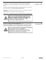
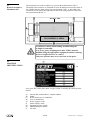
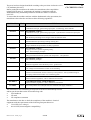
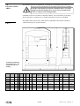
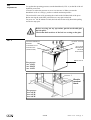
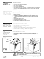
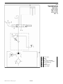
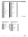
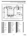
Art. 156/W
Art. P30/W
Art. 161/W
Art. 162/W
Art. 163/W
Art. 164/W
INSTRUCTIONS FOR USE,
MAINTENANCE AND SPARE PARTS
A 01 03
ENGLISH
MEDIUM SPEED
ELECTROHYDRAULIC PRESSES
Before use, place the adhesive labels enclosed with this handbook on the press, as shown in the
diagram below.
!
WARNING
FAILURE IN PLACING THE LABELS WILL LEAD TO THE EXPIRATION OF
THE GUARANTEE CONDITIONS AND RELIEVES THE MANUFACTURER OF
ANY RESPONSIBILITY FOR DAMAGE RESULTING FROM USE OF THE PRESS.
N.B.: If one or more machine labels are damaged, lost or illegible, ask for a replacement by
mentioning the relative position number.
Place the new label in the point shown in the figure below.
1
2
4
5
OMCN 156/W - 164/W pag. 2
A 01 03
Pay attention to the following hazard signals when reading the manual:
!
DANGER
!
!
WARNING
CAUTION
This signal indicates the presence of more or less hazardous conditions or situations.
The HAZARD signals are divided into three levels.
!
Non respect of this signal causes serious risks for health: death,
permanent damages at middle and long term.
DANGER
!
Non respect of this signal causes serious risks for health: death,
permanent damages at middle and long term.
WARNING
!
Lack of compliance with this signal can cause personal injuries or
damage to the machine.
CAUTION
TERMINOLOGY AND DEFINITIONS (Annex I, directive 98/37/CE)
"Operator": the person (s) responsible for installing, starting up, adjusting,
servicing, cleaning, repairing and transporting the machine.
“Person at risk”: anyone found entirely or partly in a hazardous area.
“Area at risk or hazardous”: any area inside and/or near the machine where the
presence of a person at risk endangers his/her safety and health.
“Specialized technician”: person assigned by the manufacturer to carry out
special maintenance operations requiring training and specific skills in mechanics,
electrical engineering, electronics, oil hydraulics and pneumatics.
The specialized technician is acquainted with all the possible hazards on the
machine and the necessary procedures in order to avoid injury to himself or others
during these maintenance operations.
"User": anyone who purchases or uses the machine (e.g. for renting, leasing or
under loan) in accordance with the manufacturer’s instructions.
A 01 03
OMCN 156/W - 164/W pag. 3
OMCN 156/W - 164/W pag. 4
A 01 03
User manual
TABLE OF CONTENTS:
1.0 INTRODUCTION
2.0 SPECIFIC USE
2.1 Detail of workpiece – Maximum sizes
2.2 MACHINE IDENTIFICATION
2.3 CE CERTIFICATION
3.0 GENERAL SAFETY REGULATIONS
3.1 Safety devices
3.2 Clothing
4.0 TRANSPORT
5.0 UNPACKING
6.0 MAIN TECHNICAL FEATURES
7.0 INSTALLATION AREA
8.0 SPECIFIC USE
9.0 SETTING THE PRESS AT WORK
9.1 Wiring
9.2 Motor rotation check
10.0 USE
10.1 Operation
10.2 Adjustments
11.0 ROUTINE MAINTENANCE
11.1 Changing hydraulic oil
11.2 Cleaning and replacing suction filter
11.3 Cleaning and replacing exhaust filter
11.4 Cleaning exhaust valves
12.0 TROUBLESHOOTING TABLE
13.0 SETTING THE PRESS ASIDE
14.0 SCRAPPING THE PRESS
15.0 FACTORY TESTS
16.0 OIL HYDRAULIC DIAGRAM FOR PRESSES ART. 156/W - P30/W - 161/W
16.1 OIL HYDRAULIC DIAGRAM FOR PRESSES ART. 162/W - 163/W - 164/W
17.0 ELECTRIC DIAGRAM
18.0 ELECTRIC BOX COMPONENTS
19.0 SPARE PARTS ASSEMBLY DIAGRAM
20.0 DIAGRAM OF DISTRIBUTOR’S SPARE PARTS
21.0 DIAGRAM OF HYDRAULIC POWER UNIT SPARE PARTS
FOR Art. 156/W - P30/W - 161/W
21.1 DIAGRAM OF HYDRAULIC POWER UNIT SPARE PARTS
FOR Art. 162/W - 163/W - 164/W
22.0 EXTRA ACCESSORIES
A 01 03
OMCN 156/W - 164/W pag. 5
This handbook contains all the necessary information for safely using, cleaning,
lubricating and servicing oil hydraulic presses for maintenance, manufactured
by OMCN S.p.A., via Divisione Tridentina, 23 24020 Villa di Serio (Bergamo)
ITALY
1.0
INTRODUCTION
Carefully read the warnings and instructions found in this handbook as they provide
important information on SAFE USE and MAINTENANCE.
This manual is an integral part of the product, so keep it in a safe place for the entire
product life.
If this handbook is lost or damaged, ask for another copy from:
OMCN S.p.A., via Divisione Tridentina, 23 24020 Villa di Serio (Bergamo) Italy
!
WARNING
OMCN S.p.A. CANNOT BE HELD LIABLE FOR ANY
DIRECT OR INDIRECT DAMAGE OR INJURY TO
PERSONS, ANIMALS OR THINGS CAUSED BY THE
FAILURE TO OBSERVE THE INSTRUCTIONS
CONTAINED IN THIS HANDBOOK.
The press is designed to be used exclusively for maintenance and can therefore
be used for servicing and/or making adjustments.
The press is not designed to carry out cyclic processing or quantity production
and therefore should not be used for bending, drawing or cold forging metals.
!
WARNING
Uses not explicitly indicated in this handbook are considered
improper and therefore strictly forbidden.
The manufacturer cannot be held liable for direct or
indirect damage or injury to persons, animals or things
caused by correct or incorrect use of the press.
OMCN 156/W - 164/W pag. 6
A 01 03
2.0
SPECIFIC USE
2.1
Detail of workpiece
Maximum sizes
The maximum sizes of the workpiece are given in the detailed annex (FIG. 1).
The depth of the workpiece is calculated as twice the distance between the centre of
the cylinder and rear guard of the press (measurement A FIG. 1); the width is the
maximum size allowed by the light between the load-bearing members of the structure (measurement B FIG. 1).
REAR GUARD
HAZARDOUS AREA
OPERATING AREA
!
DANGER
Avoid heavy strains when loading and unloading the
workpieces manually.
Any heavy parts (weighing more than 25 KG) must be
handled using the appropriate equipment (such as hoisting
devices, freight elevators or cranes).
Only one operator may carry out work on the press.
2.2
MACHINE
IDENTIFICATION
Every press has a name plate (POS. 4 Figure PAGE 2) showing the following information:
A)
B)
C)
D)
E)
F)
G)
H)
I)
General data, manufacturer’s complete address.
Model.
Power (thrust force in TONNES).
Year of manufacture.
Power supply in Volts.
Motor capacity in Kw.
Operating pressure in bars.
Manufacturing lot number.
CE mark.
A 01 03
OMCN 156/W - 164/W pag. 7
The press has been designed and built according to the provisions in directive 98/37/
CE (machinery directive).
Before putting the machine on the market, the manufacturer has compiled the
technical file in annex V, ascertaining the machine’s compliance with the
fundamental safety and health precautions contained in annex I of directive
98/37/CE.
To ensure that the machine conforms with the fundamental safety precautions, the
manufacturer has referred to and observed the following regulations:
REGULATION YEAR
2.3
CE CERTIFICATION
TITLE
EN 292-1
1992
MACHINERY SAFETY:
Fundamental concepts, general design principles - Terminology, basic methods
EN 292-2
1992
MACHINERY SAFETY:
Fundamental concepts, general design principals – Specifications and technical principles
EN 294
1992
MACHINERY SAFETY:
Safe distances preventing access of upper limbs to hazardous areas
EN 349
1993
MACHINERY SAFETY:
Minimum distances preventing crushing of body parts.
EN 414
1993
MACHINERY SAFETY:
Design standards and presentation of safety regulations
EN 954-1
1996
MACHINERY SAFETY:
Category of control systems regarding safety;
Part 1: General design principles
EN 982
1996
MACHINERY SAFETY:
Safety precautions for fluidic systems and components – Oil hydraulics
EN 1050
1997
MACHINERY SAFETY:
Risk evaluation principles
EN 60204-1
1997
MACHINERY SAFETY:
Electrical equipment of the machinery; Part 1: general rules
EN 60947-5-1
1991
MACHINERY SAFETY:
Low voltage electromechanical control circuit switching
EN ISO 3746
1995
ACOUSTICS:
Sound level measurement of noise sources by sound pressure – Survey method using an
enveloping measurement surface over a reflecting plane.
EN 50081-2
1993
ELECTROMAGNETIC COMPATIBILITY:
General emission regulation; - Part 2: Industrial environment
EN 50082-2
1995
ELECTROMAGNETIC COMPATIBILITY:
General immunity regulation – Part 2: Industrial environment
EN 10025
1995
Hot rolled products of not alloyed steels for structural uses supply conditions.
The manufacturer has fulfilled the prescriptions of the above-mentioned provisions
and has put the machine on the EU market along with:
User handbook
CE mark
CE compliance statement
The manufacturer also has to check the compliance of the machine’s electrical
equipment with the requirements of the following European directives:
72/23/CEE (Low voltage).
89/336/CEE (electromagnetic compatibility)
OMCN 156/W - 164/W pag. 8
A 01 03
3.0
GENERAL SAFETY
REGULATIONS
FIG. 1A
!
DANGER
STRICTLY OBSERVE THE GENERAL SAFETY AND
ACCIDENT-PREVENTION REGULATIONS LISTED
BELOW:
The machine may only be used by responsible staff in good health who have
been specially trained to use the press and are acquainted with all the risks.
The machine may only be used by operators who have completely read, understood and taken in all the information given in this handbook.
It is compulsory to check that there are no persons at risk near the hazardous areas before starting the machine.
It is forbidden to remove the guards or tamper with any of the safety devices
fitted on the machine.
It is compulsory to check that the installed safety devices are in perfect working
order before operating the press: it is forbidden to operate the machine if it is
faulty.
It is compulsory to fit the supporting pins of the work table before operating the
press.
It is compulsory to check that there are no hazardous conditions for persons at
risk during operation. If there are, stop any operations underway immediately and
keep people away.
It is compulsory to check during the piston movements that there are no objects
in area where the piece moved by the cylinder is projected.
It is compulsory to switch off the machine by means of the special switch whenever you need to gain access to the hazardous area.
Do not leave the machine without turning off the tension acting on the proper
switch.
When you have finished working with the press, it is compulsory to stop the control unit by operating the special switch to cut off the power supply.
It is forbidden to climb or get onto the press (FIG. 1A).
It is forbidden to stand near the press bed while the machine is running.
Should you notice any unusual sounds or operating faults, It is compulsory to interrupt all operations immediately and find the cause of these irregularities. If in
doubt, avoid improper operations and contact the manufacturer’s technical service
(OMCN).
Any tempering or modification of the machine cause automatically the loss of the
guarantee and relieves the manufacturer from all and any responsibilities for direct
or indirect damages caused by these tampering.
It is compulsory to make sure that the environment where the press is installed is
well-ventilated and well-illuminated. The floor on which the machine is to be installed must be solid, flat and perfectly level.
During loading, unloading and installation it is compulsory to use lifting and handling equipment with adequate capacity for the weight of the press (See FIG. 3 –
TECHNICAL CHARACTERISTICS), using lifting devices and accessories
(nylon belts, etc.) that are suitable and in perfect condition for the purpose.
We suggest during the maintenance operation to use only original spare parts
OMCN. The manufacturer declines any responsibilities for damages caused by
the use of non original parts.
The use of non original spare parts involves the automatic loss of guarantee.
It is compulsory place the press far from heat sources or from devices whom can
emit electromagnetic radiations which could cause the bad operation of the devices which are on the electric board.
A 01 03
OMCN 156/W - 164/W pag. 9
The press is fitted with following safety devices:
Hand-held controls: movements stop immediately as soon as the controls are
released.
Max. pressure valve protecting the pump: this valve limits the operating pressure
to the amount fixed by the manufacturer.
Protection device against overcurrents operated by miniature circuit breaker.
To operate the press in safe conditions, wear appropriate clothing for the machine
and working environment:
Do not wear long or flapping clothes, ties, scarves or similar garments that could
get caught up in the moving parts of the machine.
Keep long hair out of the way and sleeve ends tight; avoid wearing watches, rings,
necklaces or other objects that can injure the wearer.
Use suitable gloves and protective footwear. If the working environment has a
noise level of at least 85 dB (A), wear ear muffs or other hearing protection
devices.
In every case, refer to the safety precautions regarding working environments of the
country where the machine is operated.
OM OMCN 156/W - 164/W pag. 10
A 01 03
3.1
Safety devices
3.2
Clothing
The machine is supplied already packed in bubble wrap which protects it effectively
during transport and handling.
4.0
TRANSPORT
The packaged machine must be transported as follows:
Always protect the press and electric control unit (1 FIG. 2) against atmospheric
agents by covering them with nylon or similar material.
Check that the corners on the ends are protected with appropriate materials
(bubble wrap/cardboard).
Do not use wire rope for lifting purposes.
During lifting, sling the press with belts at least 100 cm long with a maximum capacity of over 1500 kg.
Check that the bed is fastened securely without play between the bed and structure. Any play could be hazardous.
!
USE FORK-LIFT TRUCKS TO MOVE THE MACHINE,
GRIPPING AND LIFTING IT AS SHOWN IN FIG. 2.
DANGER
!
CAUTION
FIX THE PRESS SECURELY FOR TRANSPORT IN
ORDER TO PREVENT IT FROM SHIFTING ON THE
LOADING PLATFORM OF THE VEHICLE OR
TRANSPORT EQUIPMENT.
FIG. 2
Art.
Weight of
package
Art. 156/W
Kg. 190
Art. P30/W
Kg. 320
Art. 161/W
Kg. 440
Art. 162/W
Kg. 480
Art. 163/W
Kg. 690
Art. 164/W
Kg. 900
A 01 03
OMCN 156/W - 164/W pag. 11
After unpacking, check that the machine and control equipment are perfectly intact and have not been damaged during transport. Notify the manufacturer of any
missing parts within 8 days of delivery.
If in doubt, do not use the machine and contact the manufacturer.
The packing elements are potential sources of hazards and must be kept out of
reach of children. Dispose of them in special waste collection areas.
The unconnected parts (distributor lever, bed winch crank) must be present. Each
of them are fixed with clamps to one of the cylinder pipes and the winch crank
arm.
For press Art. 156/W, which is without a winch for moving the bed, check the
distributor control lever only.
The press is supplied with the tank already containing the necessary operating oil.
Presses Art. 162/W - 163/W - 164/W work with a dual oil hydraulic pump. This
device allows high approaching speed and low speed during operation.
The two speeds are switched automatically by a special preset valve.
5.0
UNPACKING
6.0
MAIN TECHNICAL
FEATURES
Presses Art. 156/W - P30/W - 161/W are equipped with a single pump power unit.
The approaching speed is equal to the operating speed.
There is a mechanical stop at the end of the cylinder movement.
During cylinder return, you can use a working force of approx. 30% of the rating.
There are two max. pressure valves: one on the pump for protection, and the other
on the distributor for checking the control circuit.
The machine has been subjected to noise level tests in a qualified laboratory.
The tests were carried out with the machine load less and equipped with its standard
components, according to the procedures in regulation EN 3746: 1996.
The tests gave the following results:
Average acoustic radiation pressure level assessed: LpAm = 70.6 dB (A).
Acoustic radiation pressure level in workstation LpAm = 75.8 dB (A).
Acoustic power level LwA = 88.1 dB (A).
OMCN 156/W - 164/W pag. 12
A 01 03
6.1
SOUND LEVEL
The machine needs to be installed in a working area as indicated in the table (FIG. 3).
The press must be positioned on a horizontal surface that is preferably
7.0
INSTALLATION
AREA
From the control point, the operator should be able to see all the
equipment and surrounding area, to prevent any unauthorized
persons or objects from causing hazards.
!
WARNING
cemented or tiled. Avoid weak or unsteady surfaces. Any raised floors over empty
spaces must have a resistance of 35 N/mm2 equivalent to a class of 350 RBK.
The depth of the concrete layer must ensure a tight hold of the anchors and have a
sound consistency for at least 200 mm.
FIG. 3
Technical specifications
and weights refer to the
standard and are not
binding.
Art.
Power
A
B
C
D
E
F
Piston
stroke
Capacity of
rapid power
unit per 1’
Installation
area (cm)
Motor
capacity
KW
156/W
20 Ton.
1920
500
1110
510
920
140
285
lt. 2,4
lt. 2,4
600
600
200
120 x 60
1,5 KW
P30/W
30 Ton.
2000
600
1600
700
1000
180
260
lt. 4,5
lt. 4,5
575
575
330
170 x 80
3 KW
161/W
40 Ton.
2090
850
1650
775
1135
195
260
lt. 4,5
lt. 4,5
575
575
470
170 x 90
3 KW
162/W
50 Ton.
2080
850
1650
775
1135
205
260
lt. 5
lt. 2,4
600
215
530
170 x 90
1,5 KW
163/W
70 Ton.
2205
900
1755
880
1120
265
310
lt. 6
lt. 4,5
595
280
800
190 x 100
3 KW
164/W
100 Ton.
2280
900
1930
1010
1055
280
310
lt. 10
lt. 4,5
570
180
1050
200 x 100
3 KW
A 01 03
Capacity of
Speed of Speed of slow Weight
slow power rapid stem
stem per
(kg)
unit per 1’ per 1’ (mm)
1’ (mm)
OMCN 156/W - 164/W pag. 13
- 8.0 HOW TO USE - INCORRECT -
OMCN 156/W - 164/W pag. 14
- CORRECT -
A 01 03
- 8.0 HOW TO USE - INCORRECT -
- CORRECT -
A 01 03
OMCN 156/W - 164/W pag. 15
After unpacking the machine components, check that the machine and all its
components are intact. Observe the following instructions in order to set the press at
work.
A)
B)
9.0
SETTING THE
PRESS AT WORK
Fit the anchors in their holes on the base.
Fix the press to the floor, tightening the anchor bolts (FIG. 4).
To carry out the operation, observe the following instructions (FIG. 4A):
1)
2)
3)
4)
Drill at least 100 mm deep with an 18 ø tip. (1).
Clean the hole thoroughly (2).
Lightly hammer the anchors into the holes (3).
Tighten the bolts with a dynamometric wrench calibrated to 70 N/m (4).
Check that the anchors are tight every 1000 working hours.
!
WARNING
The manufacturer cannot be held liable for any damage caused by
the failure to follow the above instructions. Lack of compliance
voids the guarantee.
FIG. 4A
1
C)
D)
2
3
4
Check the oil level in the tank of the oil hydraulic power unit by means of the
special oil level indicator on the side of the oil hydraulic power unit. Top up
with “AGIP ACER 46” hydraulic oil or equivalent.
Assemble the lever on the control distributor, disconnecting it from the hard
pipe exiting the distributor.
FIG. 4
OMCN 156/W - 164/W pag. 16
A 01 03
9.1
Wiring
!
WARNING
FIG. 5
BEFORE CARRYING OUT ANY OPERATIONS, CHECK
THAT THE PARTS TO BE SERVICED ARE NOT LIVE
AND SAFELY DISCONNECTED FROM THE POWER
SUPPLY. EVEN THE SIMPLEST ELECTRICAL OPERATIONS REQUIRE RESPONSIBLE AND PROFESSIONALLY QUALIFIED TECHNICIANS.
Connect the press to the electrical power supply using the cable exiting the
electric control equipment in the following way:
Connect the cable to an automatic cutoff device against overcurrents, provided
with 30 mA circuit breaker.
Check that the power supply voltage is 400 Volts.
Check that there is an effective earth wire and that the power supply connections
comply with the regulations in force.
Should you need to replace the power supply cable, if it is less than 3 m long, use
a three-pole + ground cable, at least 4 mm2 in section. Never make any
connections on the mains line.
In the case of longer cables, the section of the power supply cable must be adapted to
the actual length.
Wiring must be carried out with the ends of the cable connected to terminals L1, L2,
L3 of the electric panel (FIG. 5).
The operating voltage is 400 Volts and the connections are provided to withstand this
voltage.
The press is provided with special devices if you need to use a 230 Volt power
supply.
To change the wiring, proceed as follows:
Check that there is no voltage by pressing the special switch.
Remove the cover from the motor’s terminal board.
Extract the nuts from the block of contact bars and invert the position of the bars,
placing them horizontally (FIG. 7).
Retighten the nuts and fit the motor’s terminal board cover back on.
Replace the originally fitted circuit breaker with an equivalent one of adequate
value. Ask OMCN’s technical assistance department for the necessary circuit
breaker.
FIG. 6 - 7
400 Volts
230 Volts
400 Volts
A 01 03
230 Volts
OMCN 156/W - 164/W pag. 17
Turn the main switch to “ON” (1 FIG. 8) to switch on the machine.
Pull the distributor level to move the cylinder. The cylinder shaft should start
descent.
Should it fail to move, invert the motor rotation.
First check the motor rotation direction through the tank cap (8 FIG. 10): it should
correspond with the arrow next to the cap.
To carry out this operation, CUT OFF THE POWER SUPPLY by pressing the
special switch and invert two power supply cable phases by inverting a pair of
terminals on the electric panel.
9.2
Motor rotation
check
The press may only be used by authorized, adequately trained, responsible and
skilled staff in good health. Pease remember that anybody who uses the press
without being acquainted with the procedures specified here could seriously
endanger persons at risk and the operator himself.
The press has a hand-held control system. Movements stop immediately as
soon control is released.
10.0
USE
Before using the machine, the operator must have read, understood and taken in the
instructions contained in this handbook.
!
WARNING
THE MANUFACTURER CANNOT BE HELD LIABLE
FOR ANY DIRECT OR INDIRECT INJURY OR
DAMAGE CAUSED BY THE FAILURE TO OBSERVE
THE INSTRUCTIONS CONTAINED IN THIS
HANDBOOK.
It is
compulsory to fit the work table supporting pins before operating the press.
!
WARNING
BEFORE CARRYING OUT ANY OPERATIONS ON THE
MACHINE, MAKE SURE YOU HAVE READ AND
UNDERSTOOD ALL THE INSTRUCTIONS IN THIS
HANDBOOK.
10.1
Operation
FIG. 8
CYLINDER DESCENT:
Set the main switch (position 1 FIG. 8) to ON.
Pull the distributor lever 3 as far as it will go.
CYLINDER ASCENT:
Push the distributor lever 3 as far as it will go.
Once again, if you release one of the two controls even for an instant, the piston stops
moving.
The piston stops instantly whenever you release the lever 3.
!
DO NOT KEEP ACTIVATING THE PISTON WHEN IT
HAS COMPLETED ITS ASCENT AND DESCENT: YOU
CAN RISK DAMAGING THE CYLINDER.
WARNING
OMCN 156/W - 164/W pag. 18
A 01 03
10.2
Adjustments
To regulate the operating pressure, turn the handwheel (1 FIG. 9) on the lid of the oil
hydraulic power unit.
Loosen it to reduce the pressure or screw it to increase it. When you turn the
handwheel as far as it will go, you have reached maximum pressure.
The work table is moved by operating the winch on the left-hand side of the press.
Before moving the work table, pull out the two stop pins on the bed.
For press Art. 156/W without a winch, the bed must be moved by hand after pulling
out the two stop pins.
!
Before carrying out any operations, put the work table pins
back in place.
Check that both surfaces of the bed are resting on the pins.
WARNING
FIG. 9
MOTOR TERMINAL
BOARD
(1) MAX. VALVE
LOADING PLUG
WITH LEVEL
(INDICATOR)
PLUG FOR
CHECKING
MOTOR
ROTATION
DRAIN PLUG
For presses:
Art. 156/W
Art. P30/W
Art. 161/W
Electric
terminal
block
For presses:
Art. 162/W
Art. 163/W
Art. 164/W
A 01 03
OMCN 156/W - 164/W pag. 19
Routine maintenance includes cleaning, lubricating, greasing and adjustments that
need to be carried out at regular fixed intervals in order to ensure that the machine
operates correctly and the safety devices are in perfect working order.
All those operations not mentioned below are considered extraordinary operations,
which may only be carried out by the manufacturer.
!
WARNING
11.0
ROUTINE
MAINTENANCE
THE OPERATIONS DESCRIBED BELOW MUST BE
CARRIED OUT BY TECHNICAL STAFF SPECIALIZED
IN MECHANICS, ELECTRIC ENGINEERING AND OIL
HYDRAULICS.
To ensure that the press operates correctly and efficiently, follow the instructions
below and perform all the cleaning and routine maintenance operations according to
the frequencies described below.
!
WARNING
CLEANING AND ROUTINE MAINTENANCE MAY
ONLY BE CARRIED OUT IN SAFE CONDITIONS. FOR
THIS PURPOSE, SET THE MAIN SWITCH TO OFF
BEFORE STARTING ANY CLEANING OR
MAINTENANCE.
EVERY DAY:
Before starting up the machine, check its overall state by making sure that the piping
is intact and without hydraulic oil leaks.
EVERY 1000 HOURS:
Replace the oil in the power unit using hydraulic oil “AGIP ACER 46” or
equivalent in the fixed quantities indicated (See FIG. 9A).
Clean the pressure regulating valves according to the instructions given below.
Clean the suction filter according to the instructions given below.
Check that the anchors fastening the press to the floor are tightened securely.
EVERY 2000 HOURS:
Replace the suction filter and clean the exhaust filter cartridge on the power unit
lid, following the instructions given below.
EVERY 4000 HOURS:
Replace the exhaust filter cartridge inside the exhaust filter cover, which is
located on the power unit. Follow the instructions given below.
Check the machine’s overall state of repair, making sure that there are no visible
signs of buckling and/or cracks on the welding.
Check that the oil hydraulic system components, piping, flexible tubes and unions
are intact.
Check the general condition of the electric system components: cable glands,
electric control unit and power supply cable.
Replace any of these components if they are not perfectly intact or functional.
OMCN 156/W - 164/W pag. 20
A 01 03
FIG. 9A
Art.
Oil
quantity
Art. 156/W
lt. 24
Art. P30/W
lt. 24
Art. 161/W
lt. 50
Art. 162/W
lt. 50
Art. 163/W
lt. 80
Art. 164/W
lt. 90
11.1
CHANGING
HYDRAULIC OIL
Change the oil as follows:
11.2
CLEANING AND
REPLACING THE
SUCTION FILTER
Replace the suction filter as follows:
11.3
CLEANING AND
REPLACING THE
EXHAUST FILTER
Clean or replace the exhaust filter as follows:
11.4
CLEANING THE
REGULATING
VALVES
Clean the regulating valves as follows:
Unscrew the cap on the back of the tank.
Empty the tank completely.
Screw the cap back on the tank.
Fill up the tank through the cap (4 FIG. 10) on the top of the tank. The quantity of
oil to be put in the tank depends on the type of power unit (see FIG. 9A) for the
quantities.
Disconnect the two flexible tubes from the valve stop on the lid of the oil
hydraulic power unit.
Lift the lid with the pump unit and disconnect the filter, undoing the screws.
Clean the cartridge with compressed air or replace it with a new filtering
cartridge.
Fasten the filter with its screws.
Put the lid and pump unit back in place.
Reconnect the two flexible tubes of the valve stop.
Take off the filter cover by loosening the screws.
Pull out the filter cartridge.
Clean with compressed air or replace it with a new filtering cartridge.
Put the cover back on, securing it with the screws supplied.
Pull the valve out of its housing (1 FIG. 10). Clean with compressed air and
petrol, handling it with care to avoid damaging it during assembly and
dismantling.
FIG. 10
5
2
1
9
4
7
For presses:
Art. 156/W
Art. P30/W
Art. 161/W
!
For presses:
Art. 162/W
Art. 163/W
Art. 164/W
Any extraordinary maintenance and repairs must be carried
out by the manufacturer.
WARNING
A 01 03
OMCN 156/W - 164/W pag. 21
12.0 - TROUBLESHOOTING TABLE
PROBLEM
POSSIBLE CAUSES
SOLUTIONS
The pumps are on but the cylinder does
not move.
1 The motor rotates in the opposite
1 Change the motor rotation by
direction.
inverting two power supply cable
2 Primary pump cut off valve is faulty.
phases.
2 Check the cut off valve spring and
3 Primary pump cut off valve is
eliminate the causes of malfunction.
broken.
3 Replace the valve spring.
With the cylinder resting on the
workpiece, the pressure does not rise
smoothly.
1 There is air in the circuit.
With the cylinder resting on the
workpiece, the pressure does not reach
the preset value.
1 No oil in the tank.
2 Suction filter is clogged up
2 Oil leak in the circuit.
3 Max. pressure valve is clogged up.
4 Max. pressure valve is broken.
5 One or more pump units are worn.
6 Cylinder gasket is damaged.
7 Cylinder liner is worn or damaged.
1 Lift and lower the cylinder stem as
far as it will go.
2 Lift the lid off the oil hydraulic
power unit (as described in the
maintenance chapter) and clean or
replace the filter.
1 Check the oil level by looking at the
dipstick on the tank cap. Top up if
necessary.
2 Check that the pipe fittings and
distributor are not leaking oil. Check
that the pipe fittings are securely
tightened and replace them if
necessary.
3 Remove the max. pressure valve,
clean it with petrol and compressed
air and check the state of the spring.
4 Replace the max. pressure valve.
5 Replace the damaged pump units
(contact the OMCN technical
service).
6 Replace the damaged gasket (contact
the OMCN technical service).
7 Replace the cylinder.
With the cylinder resting on the piece,
the pressure decreases too much when
the controls are released.
1 The distributor housings or slider are 1 Pull the slider out of the distributor
dirty.
housing and clean the slider and its
housing. If the slider is damaged,
replace the entire distributor (Chap.
21 FIG. 14).
2 Cylinder gasket is damaged.
2 Replace the damaged gasket (contact
the OMCN technical service) or
replace the cylinder.
3 Cylinder liner is damaged.
3 Replace the cylinder.
On operating the controls, the pump
does not start.
1 Thermal protection has tripped.
2 Missing phase on the power supply
line.
1 Reset the circuit breaker.
2 Check the continuity of the 3 phases
on the power supply cable. Replace
the cable if necessary.
If the problems persist, contact the manufacturer and avoid unspecific operations.
Contact the authorised centres for assistance and ask for original parts.
The list of spare parts is enclosed with this instruction handbook.
OMCN 156/W - 164/W pag. 22
A 01 03
13.0
SETTING THE
PRESS ASIDE
If the machine is set aside for long periods, disconnect all supply sources, drain
the tank of hydraulic oil and protect any parts that risk damage due to dust or
atmospheric agents.
The flexible tubes and components that risk damage due to drying out must be
adequately greased.
When setting the press at work after a long time, check that the flexible tubes are
perfectly intact without cuts, scratches or cracks.
14.0
SCRAPPING
THE PRESS
At the end of the machine’s life cycle or when you decide not to use it any more,
make it inoperative by removing all the hydraulic oil left in the tank and in the
drive cylinder.
The press must be disposed of as special waste, so dismantle it into
homogeneous parts and dispose of them in compliance with the regulations in
force.
15.0
FACTORY TESTS
Before packing, the press was subjected to operating tests regarding the parts listed
below:
Ascent - descent piston speed check.
Bed and cylinder table parallelism check.
Work table movement check.
Max. pressure valve check and calibration.
Check for no leaks or seepage from the pipe fittings.
A 01 03
OMCN 156/W - 164/W pag. 23
16.0
OIL HYDRAULIC
DIAGRAM FOR
PRESSES:
ART. 156/W
ART. P30/W
ART. 161/W
FIG. 11
Suction filter
Pump
Oil tank
Max. valve 400 BAR
(500 BAR for Art. 156/W)
F Manual distributor
H Cylinder
I Pressure gauge
M Electric motor
A
C
D
E
OMCN 156/W - 164/W pag. 24
A 01 03
16.1
OIL HYDRAULIC
DIAGRAM FOR
PRESSES:
ART. 162/W
ART. 163/W
ART. 164/W
FIG. 11/A
A
B
C
D
E
F
H
I
M
Suction filter
20 BAR cut off valve
Double pump
Oil tank
400 BAR max. valve
Manual distributor
Cylinder
Gauge
Electric motor
A 01 03
OMCN 156/W - 164/W pag. 25
17.0
ELECTRIC
DIAGRAM
FIG. 12
(*) Thermal calibration
Art. 156/W =
Art. P30/W =
Art. 161/W =
Art. 162/W =
Art. 163/W =
Art. 164/W =
SM1
M
4 Amp
6,9 Amp
6,9 Amp
4 Amp
6,9 Amp
6,9 Amp
Thermal switch
Electric motor
18.0
ELECTRIC BOX
COMPONENTS
FIG. 13
SM1
SM1 CONTACTOR SWITCH
OMCN 156/W - 164/W pag. 26
A 01 03
OIL HYDRAULIC
UNIT FOR
PRESSES:
ART. 156/W
ART. P30/W
ART. 161/W
OIL HYDRAULIC
UNIT FOR
PRESSES:
ART. 162/W
ART. 163/W
ART. 164/W
19.0
SPARE PARTS ASSEMBLY
DIAGRAM
FIG. 14
A 01 03
OMCN 156/W - 164/W pag. 27
List of components
1
2
3
4
5
6
7
8
9
10
11
12
13
14
15
16
17
18
19
20
21
22
o 23
o 24
o 25
o 26
o 27
o 28
Frame
Shelf plane for pump
Foot
Screw
Washer
Nut
Cylinder
Screw
Washer
Nut
OR gasket
DAS gasket
Stem
Spacer
OR gasket
Anti-extr. ring for OR
Guide flange
Guide ring
RS gasket
Guide ring
Dust scraper
Protection cup
Winch
Screws
Pin
Pulleys
Pulleys
Pulleys
LIST OF COMPONENTS OF OIL
HYDRAULIC UNIT FOR PRESSES:
ART. 156/W -ART. P30/W
ART. 161/W
30
31
32
33
35
36
37
39
40
41
Motor pump unit
Pressure valve
Pressure gauge
Oil level cap
Oil plug
Electric terminal board
Drain plug
Gas ring
Nut
Return pipe
OMCN 156/W - 164/W pag. 28
o 29
42
43
44
45
46
47
48
49
50
51
52
53
54
55
56
57
58
59
60
61
62
63
64
o 65
o 66
67
Metal rope
Copper gasket
Diverter group
Copper gasket
Straight union
Gas ring
Nut
Lowering pipe
Lifting pipe
Copper gasket
Union below
Gas ring
Nut
Main switch
Screws
Screw
Washer
Nut
Work cross piece
Work cross piece
Lockpin
Spacer pins
Washer
M16 screw
Crank
Handgrip
Pressure pipe
LIST OF COMPONENTS OF OIL
HYDRAULIC UNIT FOR PRESSES:
ART. 162/W - ART. 163/W
ART. 164/W
30
31
32
33
34
35
36
37
38
39
40
41
70
Motor pump unit
Pressure control valve
Gauge
Air filter
Oil filter
Oil cap
Electric terminal block
Copper gasket
Union elbow
Sealing ring
Nut
Return pipe
Oil level cap
A 01 03
(o) Parts not included
in Art. 156/W
20.0
DIAGRAM OF
DISTRIBUTOR’S
SPARE PARTS
FIG. 15
1
2
3
4
5
6
7
8
9
10
11
12
13
14
Central body
OR gasket
Spacer ring
Scraper ring
Stem
Spacer
Spring
Spacer
Ball housing
Shim
Cap
Body
Mushroom comp. valve
Copper washer
Spring
Piston ring
OR gasket
Cap
Aluminium washer
A 01 03
15
16
17
18
19
20
21
22
24
26
27
28
29
30
31
32
33
34
36
Regulator
Max. valve box nut
Maximum valve
Washer
Lever
Pin
Box lid body
Support
Lever rod
Screw
Cap
Washer
Washer
Steel ball
Cap
Cap
Washer
Cap
Washer
OMCN 156/W - 164/W pag. 29
21.0
DIAGRAM OF HYDRAULIC POWER UNIT SPARE PARTS
FOR Art. 156/W - P30/W - 161/W
FIG. 16
1
2
3
4
5
6
7
8
9
10
11
12
13
14
15
16
17
18
19
20
Tank
Tank cover
Self-locking nut
Motor nut
Motor tie rods
Stator casing
Oil level lamp
Rotor
Motor tree
Front bearing
Front motor flange
Ring
OR
Pumping body
Perforated screw
Piston
Drain plug
Washer
OR-cord
Washer
OMCN 156/W - 164/W pag. 30
21
22
23
24
25
26
27
28
29
30
31
32
33
34
35
36
37
38
39
40
Terminal board box
Cable clamp
Terminal board
Term. board fixing screws
Rear motor flange
Box fixing screws
Bleeding cap
Spring washer
Rear bearing
Tank cover
Washer
Motor support bracket
"P" flange
Pressure gauge
Wheel counter nut
Max. valve wheel
Counter nut
Max. valve
"T" flange
Drain pipe
A 01 03
41
42
43
44
45
46
47
48
49
50
51
52
53
54
55
56
57
58
59
Pump cap
Spring
Spring guide
Washer
Pump fixing screws
Spring
Spacer
Spacer
Snap ring
Cam
Pin
Spacer
Spacer
Pump bearing
Snap ring
Spring guide
Suction filter
Delivery union
Delivery pipe
21.1
DIAGRAM OF HYDRAULIC POWER UNIT SPARE PARTS OF
Art. 162/W - 163/W - 164/W
FIG. 17
Pumping
unit
1
2
3
4
5
6
7
8
9
10
11
12
13
14
15
16
17
18
19
20
Lid screws
Tank lid
Tank
Washer
Self-locking nut
Screw
Washer
Oil level light
Mot pos. flange
Rear bearing
Spring washer
Stator housing
Motor rotor
Motor shaft
Mot. supp. bracket
Motor tie rods
Front mot. flange
Front bearing
Pump unit
Blade
21
22
23
24
25
26
27
28
29
30
31
32
33
34
35
36
37
38
39
40
Pump rotor
Drain plug
Washer
OR braid
Cable clamp
Terminal block
Terminal board
Terminal board screw
Terminal block screw
Bleed plug
Air bleed filter
Return tube
Inspection lid
Exhaust filter
Washer
Washer
Nut
Filter screw
Stator ring
Screw
A 01 03
41
42
43
44
45
46
47
48
49
50
51
52
53
54
55
56
57
58
59
60
Tab
Washer
Pump screw
Suction filter
OR ring
Drilled screw
Pump washer
Spring guide
Spring
Ring
Pumping body
Piston
Spring guide
Pumping element bearing
Spacer
Eccentric
Spacer
Spacer
Spring
Needle bearing
OMCN 156/W - 164/W pag. 31
In order to get better the operations of the machine, and in the meantime to give more
safety and functionality to the use of the machine, OMCN supply extra equipments
suitable to the different models presented in the manual.
The different equipments suitable for every model of machine are reported on the
OMCN general catalogue.
The specific instructions for the safety use of the equipment are supply with the
equipment itself and are not reporter in this manual.
OMCN 156/W - 164/W pag. 32
A 01 03
22.0
EXTRA
EQUIPMENTS
NOTES:
A 01 03
OMCN 156/W - 164/W pag. 33
24020 VILLA DI SERIO (BG) ITALIA
Via Divisione Tridentina, 23
Tel: 035/423.44.11 r.a.
-Fax (Italy) 035/423.44.41 - 035/423.44.42
- Fax Export: +39/035/423.44.49
OMCN/INTERNET:
http:// www.omcn.com
http:// www.omcn.it
e-mail: [email protected]
e-mail: [email protected]
Dealer's stamp:
A 01 03