1
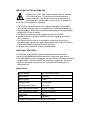
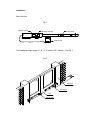
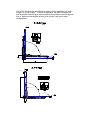
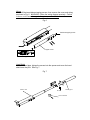
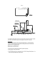
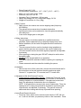
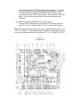
YG101 SWING GATE OPENER
OWNER’S MANUAL
IMPORTANT SAFTEY INFORMATION
Installing the YG101 Gate Opener requires wiring of standard
110V electrical lines. This should only be performed by a
trained technician. Mis -wiring could cause personal injury or
DEATH. To prevent the risk of electrocution, be sure to turn off all power to
the YG101 until installation is complete.
• The YG101 model gate opener is for a double-sided gate. The length of
each section of the gate can be no greater than 6.5 feet for this opener to
operate properly. Do not attempt to use this gate opener with a gate length
greater than 6.5 feet (2 meters).
• The maximum force that the gate opener can provide is 1500N.
• An electric lock is provided for installation for gate lengths greater than 5
feet (1.5 meters).
• In the event of power failure, an emergency release key allows you to
operate the gate manually (for gate lengths greater than 5 feet [1.5 meters],
it is recommended that you unlock the ele ctric lock).
• The gate can be opened or closed in manual mode.
ADDITIONAL FEATURES
• An interface for an optional keypad is available on the control board.
• User may add additional remote controllers to operate the gate opener.
• This gate opener includes emergency stop and reverse functions if it senses
an obstruction. This feature MUST be tuned prior to operation. Be sure to
follow the directions in the section on Tuning the Auto Reverse prior to
operational use.
Specifications
Power Supply
AC 110V±10%V, 60Hz
Motor Speed
1680 rpm
Motor Output
100W
Opening Time
<26 seconds
Working Angle of Gate
90° or 105°
Max. Gate Section Weight
330 lbs. (150kg)
Max. Gate Section Width
6.5 feet (2 meters)
Duty Cycle
25%
Noise
<65dB(A)
Emergency Release Key in Case of Power Failure
Parts List
1
Hood pipe
22
24T ring gear
2
End joint
23
Locating shield
3
Pin 10x40
24
Motor
4
Steel tube
25
Capacitor bracket
5
Small support ring
26
Capacitor
6
Right housing
27
Wiring base
7
Screw M5x20
28
Wiring terminal
Locknut
29
Screw M4x8
8
Screw shaft
30
Wiring cover
9
Connect socket
31
Tapping screw
9A
Split ring
32
Joint block
10
Tapping screw
33
Axle pin
11
Outer tube
34
Earth wire
12
Large support ring
35
Release key
13
Bearing 6004
36
Lock
14
Pin 8x35
37
Seal 17X2.65
15
27T ring gear
38
Upper cover
16
Planetary gear
39
Screw 4.2x9.5
17
Central gear
40
Waterproof seal
18
Pin 4x20
41
Hexagonal nut
19
Seal 13.2x2.65
42
Light housing
20
Square gasket
43
Waterproof seal
21
Spring
7A
Parts Diagram
7
6
25
26
5
27
28
29
4
3
30
2
31
24
32
23
33
22
34
21
1
20
18
17
15
19
43
16
14
13
12
11
42
41
10
9A
9
8
7A
40
39
38
37
36
35
Installation
Main Structure
Fig.1
Special motor
Planetary reducer
Screw shaft
Control box
The installation height range is 1.18 – 3.15 inches (300 – 800mm). See Fig. 2
Fig.2
Gate pillar
Gate opener
Gate
Electric lock
One of the first decisions that should be made is if this installation is a “push
to open” or a “pull to open.” In either configuration, the gate is mounted on
one face of the mounting post, and the opener is mounted on face 90 degrees
from it. Below are schematics of both “push to open” and “pull to open”
configurations.
Retainer
(close position)
Gate opener
Enlarge
Retainer
(open position)
When the opener is installed, the installation angle should be >0°. See Fig. 3.
The baseboard should be fixed to the pillar of the building. See Fig. 3
Enlarge.
Fig. 3
Retainer
(close position)
110
A
140
130
B
125
115
Cmax
50
50
¦Á
90¡ ã
105¡ ã
A
B
Á
1020
¦
Gate opener
Cmax
Enlarge
Retainer
(open position)
>0¡ ã
Front and Rear Parts of Gate Opener
To install the rear part of the gate opener, insert shoulder screw and spacer,
then tighten with the nut. See Fig. 4.
Fig. 4
Shoulder screw
Rear part of
gate opener
Support bracket
Spacer
Nut
To install the front part, fit the hole in the front part with the hole in the
supporting pla te, and push the axle pin into the holes (using hands or a
hammer), and finally fit the retainer clip. See Fig.5.
Fig. 5
Supporting plate
Axle pin
Front part of gate opener
Retainer clip
Wiring
Screw off the two stainless tapping screws, then remove the cover and wiring
as shown in Fig. 6. WARNING: Follow the wiring diagram precisely. Failure
to do so could cause damage to the gate opener controller.
Fig. 6
Stainless tapping screw
M
U V W
Upper cover
Enlarge
Hood Shield
Install the hood pipe, tighten the screws into the opener and cover the hood
shield over the joint. See Fig. 7.
Fig. 7
Main unit
Hood pipe
Hoodpipe
Scew
Hood shield
Waterproof caps
There are 8 caps in total – 4 to be used and 4 spares. When the gate opener
is installed, the caps are used to cover the upper holes of the unit to avoid
leakage. See Fig. 8.
Fig. 8
Waterproof cap
Gate opener
Retainer – Closed and Opened Positions
Close the gate section to its fully closed position, fix the retain er according to
the position of the gate section. NOTE: Each section is completed
separately. See Fig. 3.
If the maximum angle for installing is 105°, the retainer should be installed on
the ground at approx. 100°. If the installing angle is 90°, the retainer should
be installed at 90°. See Fig. 3.
Electric Lock
If the gate section is >5 feet (1.5 meters), it is recommended that you install
the electric lock. Weld the steel plate of the lock to the gate, and then fix the
lock. See Fig. 9 to determine height of the plate.
Fig. 9
A
Release here
Electric lock
Base plate
To install the base plate of the lock, fix the plate to the ground with 3 screws
and make sure that the lockpin can fit tightly in the hole in the plate.
Adjustment
The pair of gate sections will not start simultaneously. The gate section
without the lock will start earlier than the other gate section, so that both
sections can be locked properly.
Maintenance and Electrical
• Check the screw lubricant and add 1# grease regularly.
• Keep opener clean at all times.
• The XF24B control box is designed for the YG101 Swing Gate Opener. Its
main technical parameters are as follow:
o
o
o
o
o
o
o
Power Supply: AC 110V
Environmental Temperature: 14°F ~ 104°F (-10°C ~ +40°C)
Motor: AC 110V, max. power 735W
Electronic Lock: DC 12V 2A
Operating Time: 20 seconds ~ 100 seconds
Relay Coil Voltage: DC 12V, SCM power supply: DC 5V
Weight of Control Box: 4.4. lbs. (2Kg)
• Main Function
o Radio control, the receiver can receive hopping code (frequency:
433.92MHz).
o The gate will auto-reverse when it contacts obstruction.
o Auto-close function can be selected to close the gate automatically
after delay time.
o It can control single-gate or dual-gate .
• Safety Instructions
o The gate opener s hould be installed by a qualified technician;
otherwise, serious personal injury or property damage may occur.
o Before installation, all the locks of the gate should be removed or
unlocked.
o The auto-reverse function must be checked during installation to
ensure that the gate can auto-reverse in the event of obstruction.
o This auto -reverse function should be regularly inspected and adjusted,
if necessary.
o When opening or closing the gate, DO NOT attempt to walk or drive
through the gate.
o DO NOT touch the gate while it is in operation.
o The opener should be switched off before repairing it or opening its
cover.
o Please erase and reset the code after installing the opener.
• Installation
o Remove the cover of the control box, remove the control board and fix
the control box on the wall, perform the wiring and cover again.
Connect “L” to power line, “N” to neutral, and “E” to earth wire.
• Adjustment of the Auto-Reverse Function
o Tuning the auto-reverse safety function: Rotate the “Force Adj.” Knob
with a screwdriver. The resistance may be increased or decreased by
rotating clockwise or counterclockwise. If the gate can be removed
freely, the adjustment of obstruction force is completed.
NOTE: If the gate fails to reverse in the event of obstruction. Then, the
opening force or closing force should be checked for conformity with
requirements, and adjusted, if necessary. The gate will reverse if
obstructed when closing and will stop if jammed when opening.
• Learn/Erase Remote Controls
o Press red “learn” button on the control board, then the “LED” will turn
on. It will turn off when you press any button on the transmitter. Press
the same button and the “LED” will flash at 2Hz frequency. If it fails to
learn, the “LED” will turn off automatically after flashing for 1 sec ond.
o To erase all remote controls, press and hold the red button on the
control board until the “LED” stops flashing. After 1 second, it will flash
again. This indicates that the remote controls have been erased
completely.
• Install the External Keypad/Button Switch (See Table 3)
o The port “GND” is the common port, the port “K” is used to open the
gate, “G” is used to close the gate, and “T” is used to stop the gate.
Note : If the gate running direction is not correct, please change wires “V1 and
W1”or “V2 and W2”. If the wiring between two gates is wrong and the gates
cannot work, please check the wiring between “U1, V1, W1”and “U2, V2, W2”.
Fig. 1 0
Control Board
Table1: Wring Notes of Control Board
No.
1
2
3
Interface function
Transformer output
Transformer input
Fuse
4
Adjusting knob (for No.1 gate
which has electrical lock)
5
Adjusting knob (for No.2 gate)
6
7
8
9
10
11
12
13
14
Antenna
Power indicator light
Indicator light
Learn button
Mode switch
External button interface
External device interface
Electrical lock interface
Alarm lamp interface
Capacitance interface of No 2
motor
No 2 motor interface
Capacitance interface of No 1
motor
No 1 motor interface
Fuse
Power supply
Buzzer
15
16
17
18
19
20
21
Remark
AC12V
AC110V
5 20 2A
The resistance may be
decreased by rotating
anticlockwise.
The resistance may be
decreased by rotating
anticlockwise.
Impedance: 50O
1206
1206
66
See table 2
See table 3
See table 3
DC12V
AC110V
×
increased or
clockwise or
increased or
clockwise or
×
Suitable for No 2 motor
See table 4
Suitable for No 1 motor
See table 4
5 20 10A
AC110V
It will ring if the gate is jammed.
×
Table2: Mode S witch
No.
1
2
3
4
5
6
7
8
Position
ON
OFF
ON
OFF
ON
OFF
ON
OFF
ON
OFF
ON
OFF
ON
OFF
ON
OFF
Remark
Single- gate
Dual - gate
Single- gate: for No.1 gate
Single -gate: for No.2 gate
Dual - gate: first open last close
Dual - gate: two gates open or close at the same time
Enables auto-close
Disables auto-close
For swing gate
For sliding gate
Working time is 60s
Working time is 90s
Single button
Three buttons for remote controller
NOTE: Be sure the factory preset of bit 3 and bit 5 of the mode switch is “ON”,
please DO NOT adjust it.
Table 3: Wiring terminal for external button / external device
No.
Tag
1
2
3
4
5
6
7
8
9
12V
GND
IC
IR
LD
5V
K
G
T
Remark
Output +12V 100mA
Ground
N.O.
Infrared N.C.
Loop-detector interface
Output +5V 100mA
External button: Open
External button: Close
External button: Stop
Table 4: Connection between control board and operator
No.
1
2
3
4
5
6
Tag
U1
V1
W1
U2
V2
W2
Remark
No.1 motor: COM/U
No.1 motor: V
No.1 motor: W
No.2 motor: COM/U
No.2 motor: V
No.2 motor: W
Gatekeeper Ltd.
PO Box 752
Laceys Spring, AL 35754
[email protected]
© 2005-2007
GatekeeperLtd All Rights Reserved