1
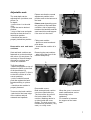
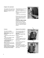
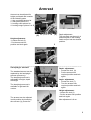
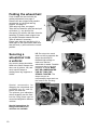
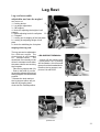
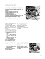
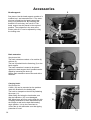
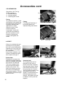
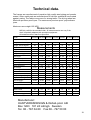
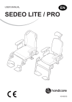
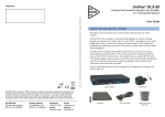
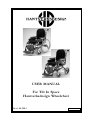
USER MANUAL
For Tilt In Space
Hantverksdesign Wheelchair
Art.nr. 95 008-1
Rev. 021211
Contents
Side
2.
3.
4.
5.
6-8
9
10
11-13
14-16
18
19
Contents
Identifying models
Wheelchairs parts
Brakes
Wheels, anti-tippers
Seat, back, covers, push bars
Arm support
Folding
Leg rests
Accessories
Maintenance
Technical data/measuring table
Model production number (NR)
A label with the model and the
manufacturing number of the wheelchair
is placed on the front frame of the chair
(see picture 2a)
1pic 2a
This User Manual’s contents applies to the following
wheelchair models:
Model 500
Model 600
Model 800
The models with bold print are the most usual and are the ones
illustrated in this user manual.
2
Wheelchair parts:
8
9
11
7
12
10
13
1
3
2
4
6
14
5
15
pic 3a
1
2
3
4
5
6
7
8
Leg rest
Foot plate
Ankle support
Driving wheel
Castors
Parking brake
Arm support
Push bar
pic 3a
9
10
11
12
13
14
15
Brake handle
Brake lock
Back adjustment lever
Seat adjustment lever
Thorasic support fastening
Folding pin
Anti tipping protection
Standard equipment:
Removable adjustable leg supports
Arm rests are adjustable height/depth
Puncture free tyres
Tipping protection
Attendant assisted disc braking
Quick release wheels
Angled seating with built in pressure relief
Angled & contoured back rest
Adjustable seat depth
Removable washable seat & back cushions
Removable other fabric covers
Height adjustable push bar
Thorasic support fastening
3
Brakes
Combined braking
All models have standard
braking equipment. Brake used
by the carer is a braking bar
located on the back of the chair
beneath the push handle. The
brake operates the disc brakes
on each wheel. NB: some
chairs can be equipped with
separate push handles but the
braking system is the same.
Brake bar: The brake is
manoeuvred by pulling up the
brake handle (1) against the
push bar (2) see picture 4a.
3
1
pic 4a
2
Parking brake: Pull the
braking handle (1) see
picture 4 a up towards the
push bar (2) and push the
lock sleeve forward (3) so
that the handle is locked in
the braking position, see
picture 4b
pic 4b
NB: One lock on each side,
make sure that the brake
sleeve is securely pushed
on so that the wheelchair is
safely braked.
Parking brake on models fitted with 24” wheels:
On model 500 there is a
separate parking brake for
the user. This brake is fitted
on the wheel rim, see
picture 4c. At braking pull
the lever (6) forward from
the wheel. There is a
braking lever on each side.
Adjusting the tyre brake:
- Loosen the stop screws (7)
- Push the brake to or from the
tyre.
- Screw in tight to the stop
screw.
IMPORTANT
adjustment of brakes should
be done by trained staff
7
6
pic 4c
Adjusting disc brakes:
The disc brakes can be
adjusted in the following
manner:
See picture 4d, loosen the
nut (8) a couple of turns. Turn
the screw (9) so that suitable
braking power is achieved.
Test the braking on the
driving handle and adjust so
that both wheels have the
same braking power and then
tighten the nut (8).
4
NB: To try out the braking
power the wheels must be
fitted.
IMPORTANT
adjustment of brakes should
be done by trained staff
pic 4d
9
8
Wheels
All wheels are fitted with
puncture
proof
tyres
(pneumatic is option) . The
driving wheels are quick
release and are either 24” or
12 ½” wheels.
Releasing the wheels:
Push in the locking knob (1)
on the underside of the wheel
hub, see picture 5a. Loosen
the wheel and take off.
Mounting wheels:
Put the wheel axle into the
socket (2) on the wheel hub
see picture 5b. Push in the
lock knob (1) on the underside
of the wheel hub. Push in the
wheels so that the three metal
pegs on the wheel hub fits
into the three holes in the
braking plate. Let go of the
locking knob and check that
the wheel is on securely.
1
picture 5a
IMPORTANT
Check that the wheel
release button has locate
and that the wheel is secure.
Moving forward the driving
wheel.
This can only be done on
model 500 (not on children’s’
models)
See special documentation.
IMPORTANT
Moving forward the driving
wheel should be done by
trained staff only.
2
picture 5b
1
Tipping protection/bar
Tipping protection is standard
on models 500, 600 and 800.
See picture 5c and 5d. The
tipping protection can be
pulled out or pushed in (lock)
picture 5d. Please note check
the locking nut has slid out of
its hole properly.
Always have the tipping
bar extended out if there is
a risk of tipping
backwards.
3
picture 5c
4
3
picture 5d
4
5
Seat and back
The control levers for control
of the seat and back angles
are on the back of the back
support, see picture 6a. The
levers are positioned on each
side of the head rest fastening. The levers should be
handled with average force.
Picture 6b shows the chair
with the back and seat at the
maximum angle with standard
gas assisted spring mounted.
picture 6a
Tipping
protection
picture 6b
Seat angling mechanism.
The tipping lock is fitted with
an adjustable brake, see
picture 6d. The brake (1) is
adjusted with a Philips
screwdriver and is adjusted to
the required for resistance
and the weight of the user.
To get access to the tipping
lock the cover (2) picture 6c,
has to be removed. The cover
is fixed with spring loaded
hooks on the frame bar and
can be removed without
tooling.
picture 6c
2
6
picture 6d
1
Back angling, left adjuster:
Control left lever.
- Grasp the driving bar with
one hand.
- Free the lever by putting
the lever to the side. Adjust
the angle by using the push
bar as a jack and let go of
the lever. Do not use the
lever as a jack. The angle
of the back is adjustable by
the gas spring with a
smooth action. As an
option there is a variant for
increasing the back angle.
The tipping risk is increased
and extended tipping
protection should be used.
Seat
angling:
See side
5.
Right side: Grasp the push
bar with one hand and free
the lever by putting the
lever to the side. Adjust the
angle by using the push
bar as a jack and let go of
the lever. The angle of the
seat is adjustable into
approx 10 positions . As an
extra there is a variant for
increasing the seat angle,
with an extended tip bar.
The tipping risk should be
taken into consideration.
Please see special fitting
manual.
Adjustable seat:
The seat depth can be
adjusted into 4 positions, see
picture 7a
for depth :
- put the lever 1 to the side
(left).
- push the seat to desired
position.
- let go of the lever and push
the seat so that the lever is
locked into position.
- check that the seat is
properly locked into position.
Removable seat and back
cushions:
Seat and back cushions are
fastened on to the wheelchair
with velcro (2) see picture 7a,
and easy to remove/change.
Alternative cushions and
covers are available.
To fit the cushions:
- fasten the poppers on top of
the back cushion on the back
of the back board (3)
according to picture 7c (this is
so that the cushion is in the
correct position).
- put the cushion forward
push fast against the back
board according to picture
7d.
- check that the cushion is
properly fastened.
To remove the back cushion:
- take hold of the lower edge
of the cushion and pull
outwards and upwards.
1
Please note that the normal
adjustment position is the
position next to the last one at
the back.
Please note depending upon
the position of the back there
could be a risk of squeezing
between the back bar and the
seat board this could happen
if the user is in the chair.
2
picture 7a
Fitting seat cushion.
- place over seat board and
push down.
- check that the cushion is in
place.
Removing the seat cushion:
- take hold of the front of the
cushion and pull up.
picture 7b
3
picture 7c
picture 7d
Removable covers:
Both seat and back cushion
covers are fitted with zips.
The front of the zip you will
find on the back of the
cushion. Washing advice is
on label inside the cover.
Option: The cloth cover has
incontinence protection ( only
seat ) or a vinyl cover.
When the cover is removed
small modifications can be
done simply to the
upholstery
For instance to increase
the support of the lower
back.
7
Height of the seat back:
The height of the seat can be
adjusted 3 cms up and 4 cms
down. This requires a 4 mm
Allen key.
Height adjustment of the back
- loosen the screws (1)
picture 8a a couple of turns (4
pcs).
- carefully push the back up
or down.
- fasten the screws properly.
1
Please note! Check carefully
that the brake wires are not
damaged when the back is
adjusted.
Please note! When the back
is moved to maximum height
that top hole on the back
frame is covered. The push
bar can be restricted and not
able to be used at its highest
position.
pic 8a
2
Pushbar:
Separate driving handles:
The chair is normally
delivered with push bar (2)
(picture 8b)
Adjusting the height of the
push bar:
- grasp the push bar with one
hand
- push in the lockpin (3) and
pull the push bar up
- hold it up and push in the
second lockpin (4).
- put the push bar in the
desired position.
Note: Check that both locks
are positioned in the holes in
the back frame.
Please note that the brake
cables are free and should
lie along the back frame.
The chair as an alternative
can be equipped with
separate push handles (5)
picture 8c.
Adjusting the height of the
handles:
- loosen screws (6)
completely.
- move the handles until the
desired position and fasten
the screws.
Check that the screws are
properly fastened.
Check that the
brake cables are running
freely and not damaged. They
should run freely along the
back frame.
4
3
pic 8b
5
6
pic 8c
8
Armrest
Armrest can be adjusted for
height and depth and consists
of the following parts.
1. Arm rest board picture 9a
2. Side panel picture 9 a
3. Locking catch picture 9a
4. Locking tongue picture 9 b 2
1
3
(6) b
picture 9a
a
Height adjustment:
- Loosen the lock (3)
- Put the armrest into
position and lock again
(5)
4
picture 9b
Depth adjustment:
The arm plate can be put in 4
positions push in the locking
catch and put into the desired
position.
3
picture 9c
Hemiplegic armrest
7
8
The standard armrest can be
replaced by the hemiplegic
armrest (accessory).
The hemiplegic armrest is
adjustable in height, depth
and angle.
The hemiplegic armrest is
available in right and left
version.
The armrest can be adjusted
in side position by loosening
sthe screws (9), picture 9e.
picture 9d
3
Depth adjustment:
- Loosen the lock (8)
- Put the armrest into
required position and lock
again.
Angle adjustment:
- Loosen the lock (7).
- Turn the armrest into
required position and lock
again.
Height adjustment:
- Loosen the lock (3)
- Put the armrest into position
and lock again
Max adjustment is 8 cm.
9
picture 9e
9
Folding the wheelchair:
Push forward the seat unit with the
seating adjustment, see page 6.
Remove the arm support and possible
accessories eg; the trunk and leg
support, see page 15.
Take away leg rests, see page 1.
Take with one hand the push bar and pull
out button (1), see picture 10a
Gas spring (2) will then fall down from the
fastening (3) and the back support can
be pushed forwards towards the seat.
Take off wheels if necessary
Please note when the gas spring (2) is
fitted again to the back frame make sure
that the knob (1) will lock into the correct
position
Securing a
wheelchair into
a vehicle:
Any security straps should be
fitted to the wheel frames side
tube, see (4) picture 10b, and
never secure straps to
seating frame leg supports or
similar.
3
1
NB: Do not put too much
strain on the leg supports the
straps should only be
fastened tight enough to
make sure that the
wheelchair is stable. Possible
movement due to low tyre
pressure or similar MUST
NOT BE COMPENSATED
FOR BY TYING THE
STRAPS TIGHTER. The
straps can put an
unnecessarily large strain on
the frame if the securing
straps are too tight.
picture 10a
2
4
picture 10b
Special accessories for
strapping the wheelchair are
available see (5) and (6),
picture 10c and 10d.
The pictures give indications
where strapping can be fixed,
but the fixing points can be
moved and angled for different
vehicles.
Special instructions for
fixing wheelchairs into
vehicles are available.
10
5
picture 10c
picture 10d
6
Leg Rest
Leg rest/removable
adjustable and can be angled
see picture 11a
1. Locking device
1
2. Leg angle adjustment
3. Calf support
4. Knob for adjusting the height of calf
support
2
5. Depth adjusting knob for calf plate
6. Footplate
7. Locking nut for angling of the foot plate
8. Locking for adjusting height of foot
plate
9. Knob for stabilising the foot plate
3
10
9
5
Angling of the leg rest:
The leg rest can be adjusted to
five different angles. The
closest angle is only intended
for transportation. The
wheelchair can normally not be
driven in transport mode when
the castor wheels are touching
the footplate.
- Take the leg support bar (10)
- Push in the knob (2) on the
leg angling adjustment and put
the leg support into the desired
position.
- Release the knob and put
the leg support either way so
that the leg angling knob
clicks into the locked position.
4
6
7 8
picture 11a
LEG SUPPORT REMOVAL:
- Loosen off the locking knob
(1) see picture 11a, by turning
anti clockwise a few turns and
then pull out the threaded knob.
Remove the leg support, see
picture 11b and lift off.
1
picture 11b
picture 11c
picture 11d
11
Leg Rest contin.
Height adjustment of the foot
support:
- Loosen the knob (9) a
fraction, see picture 12d
- Push in the locking knob
(8) and move the foot rest
bar to the desired hole
- Fasten the knob a fraction
(the knob’s function is
to
reduce the slack
in the foot
rest bar)
Angling of the footrest:
- Loosen the locking nut (7)
see picture 12a
- Angle the footplate to the
desired position
- Secure the locking nut
properly.
5
8
9
7
picture 12a
Leg rest 90o
This leg rest allows for the
seating to be at a 90o knee
angle. To achieve this both
leg rest bars (10) picture 12b
and calf support bar (12)
picture 12b, is different from
standard. They are
removable and adjusted in
the same manner as a
standard leg rest, see picture
11, but they cannot be angled
to the same height.
When using the 90o leg rest the
wheelchair must be fitted with
castor adapters (13) picture 12
b, as well as 125mm castors.
10
12
picture 12b
13
Amputee leg rests:
The wheelchair can be fitted
with amputee leg rest. It has
the same fastening as the
removable standard leg rest
and can be easily changed.
When removing see advice
for the “removal of leg rest”
page 11. When angling the
leg rest see the advice
“angling of leg rest” page 11.
12
With screw (4), picture 12c
the calf support (3) can be
put into different positions.
The calf support bar (5), see
picture 12c, can also be put
into three different positions
with a screw from inside of
leg rest, to give more
adjustment.
3
5
4
picture 12c
ALTERNATIVE LEG REST
The wheelchair can be fitted with a complete fixture
as a unit frame this is possible to angle but not
remove and is of a stable construction.
A complete leg frame can be supplied with the
following:
Separate footplates see picture 12a
Complete footplate see picture 13a
Footbox see picture 13b
The leg frame see picture 13a
Comes with a complete calf support see 13a and
it comes with padding that can be angled
The footplate 14 can be folded toward the calf
plate for getting in and out of the wheelchair.
It is also possible to adjust the angle of the foot
plate
12
13
14
16
15
ANGLE ADJUSTMENT OF
THE LEG FRAME
The leg rest can be put into 5
different
positions
the
innermost one is only used in
transport
The wheelchair cannot be
driven in transport mode when
the front castors are touching
the foot plates
· Take the leg frame with one
hand
· Push in adjustment knob
16 picture 13a to free the
lock
· Adjust the leg frame into
the desired position
Let go of the knob and push
the leg frame either way so
that the lock clicks into place
NB: The adjustment knob is
on the standard chair is
mounted on the right hand
side of the chair can if
necessarily be changed to left
hand side.
ANGLING OF THE FOOT
PLATE
· Loosen off the locking knob
see picture 13 a
· Angle the footplate nut to
desired position
Make sure the locking nut is
correctly fastened
HEIGHT ADJUSTMENT OF
THE FOOTPLATE AND
FOOTBOX
Push in the locking nut and
move the footbar to desired
hole see picture 13a and click
into place
picture 13a
picture 13b
17
17
13
Accessories
6
Head support:
See picture 14a the head support consists of a
cushion bar 1 and extension bar 2. The extension bar is fitted into the head support fastening 3 on the back rest. By loosening the
knobs 4 & 5 and using the nuts 6 & 7 the
head support can be placed in the required
position. The resistance in the nuts at the
friction joints 6 & 7 can be adjusted by using
the locking nuts.
1
4
2
7
5
3
pic 14a
Back extension:
See picture 14b.
The back extension consists of a cushion (8)
with bar (9).
The bar is pushed into the fastening (3) on the
back support.
The back extension is meant to be placed
against the back support but if needed can be
raised by loosening the knob (5).
NB the back extension cannot be used with a
headrest.
8
9
5
3
pic 14b
Carrying hook:
See picture 14c
A hook (10) can be mounted on the pushbar
under the bracket for the braking bar.
The hook is clamped on the tube by fastening
the screw (11).
When fitting and using the hook make sure
that the brakewire (12) is not damaged.
NB: When items are hung on the hook the risk
of tipping backwards is more dependant upon
the weight as well as the back and seating
angle position. It is up the Carer/user to
control the tip risk and make sure that tipping
protection is used.
14
11
10
pic 14c
12
Accessories
Shoulder support:
See picture 15 a & 15b
The shoulder support
consists of a cushion with
brackets (1)
The shoulder support is fitted
onto the pushbar and
clamped on the tube.
When fitting the push bar
must be pulled out of the
back frame and take care of
the braking cables.
The shoulder support is
locked with knob (2) which
can be put in the best position
by pulling the button straight
out and turning.
Thoracic Support:
See picture 15c and 15d.
The thoracic support consists
of a cushion (3) and fastening
(4). The fastening is normally
included in the standard
equipment of the chair.
The bracket is fitted into the
fastening and is locked with
knob (5).
By loosening the screws (6),
same screws also hold the
back plate, the fastening can
be adjusted for height.
Tray
Tray (7) is fastened to the
chair by pushing in the tray
bars (8), picture 15e, into the
sleeves of the armrest.
The left bar is longer to make
it easier locate.
Angle the tray upwards like
picture 15f makes the bars
visible.
1
2
picture 15b
picture 15a
4
3
pic ture15c
3
6
5
The fastening can also be
turned to increase the
adjustment
NB: It is important that the
screws (6) are tightly fastened.
picture 15d
7
Tools are placed under seat.
NB: When first using the tray
the width between the tray
bars must be adjusted.
Loosen the knobs (10) see
picture 15f, on the tray
bracket enough that the tray
bars can be adjusted.
Push into the armrest sleeve
make sure it is straight.
Fasten the knobs so that the
tray is stable but not too tight
to angle. The left long tray bar
is fitted with a clicking in knob
so that the table can be
locked into place. Push the
lock in a fraction so that it can
slide into arm rest sleeve and
click into place in the sleeve.
8
picture 15e
10
9
picture 15f
15
Accessories cont
LEG SEPARATING
See picture 16a. The leg
divider consists of
1. Pommel cushion
2. Pommel bracket
3. Fastening with screw
Fixing:
The pommel cushion (1) with
the bracket (2) is pushed into
the fastening (3) and locked
into place with the knob.
Adjustment of depth:
Open the cover on the
pommel cushions
underneath. Loosen the
screw with a screwdriver.
Move the pommel on the
bracket to the desired
position and tighten the
screw.
1
2
Fitting:
For fitting and fastening of
leg divider please see
separate fitting instructions.
Picture 16a
3
Picture 16b
LAP BELT
If there is a risk that the user
could slip out of the chair a
belt can be used. NB special
restriction for use of belt can
exist, contact your therapist
for information.
Lap belt are available in two
versions. Divided belt type 2
and complete belt type 1.
Divided belt:
Divided belt is meant to be
used with a special fastening
which are available as extras
see pictures 16c and 16d.
The belt is equipped with
velcro at both ends and a
buckle in the center. The
ends of the belt are put into
the holes in the fastenings
and pushed together. The belt
is adjustable maximum length
about 110 cms.
16
Picture 16c
Complete belt:
The complete belt can be
fastened on the chair as
picture 16e shows, between
seat and back frame. Please
note the belt should be over
the gas spring see 2 picture
10a. So that the stretch is not
altered when the back is
angled. The belt can also be
fastened behind the back
support. NB. Make sure that
no cables or other parts are
trapped.
Picture 16d
Picture 16e
3
Common safety aspects
The wheelchairs can be used both indoors and outdoors.
Before using the wheelchair it is important that user and attendant is well
informed of the function of the wheelchair and how it should be used.
Test driving and functions.
Read the complete manual and keep it available.
Note, there can be some deviation if the wheelchair is optional equipped.
For safety it is important to follow maintenance instructions.
A good rule is to keep the chair clean and regularly check brakes and
adjustments.
Especially after transportation, checking for damages on cables or similar
is recommended.
To avoid risks use the wheelchair with judgement.
Child should only be attendent under supervision of adult.
Risk of tipping:
The risk of tipping backwards is increased if the wheelchair is equipped
with the options increased back angle and seat angle. In this case the
wheelchair should be equipped with extended tipping protection.
Note, the risk for tipping is increased when the back is loaded with bags,
especially when seat and back is in backward position.
Finger traps:
When adjusting the wheelchair the attendant should always be observant
that the user not get jammed, even if the risk normally is small.
17
Maintenance
General recommendations reference maintenance. To achieve the best safety and long
life the wheelchair should be kept clean and tidy. Possible faults and small changes
should be immediately corrected. How this chair is used will prolong the chair’s life and
how the chair is used will influence the maintenance. Hard use outside will result in
more maintenance.
18
How often?
Type of Maintenance
1
Running
maintenance:
Can be done by
carers by using this
manual.
No special training
is necessary.
Cleaning as necessary.
Wash all painted surfaces & treated surfaces.
- Wash with normal with non abrasive cleaners.
- Faults in the paint work should be repaired.
- Paint is available from manufacturer/dealer.
Plastic components:
Wash/wipe with normal cleaning products.
Upholstered covers:
- Clean/wipe with textile cleaner.
- Removable covers can be machine washed ,
see label inside cover.
Check for small defects.
2
Once/twice yearly
Can be done by
carer by using this
manual.
No special training
is necessary.
General check of wheelchairs condition:
- General cleaning
- Check all functions, even those not used.
If necessary lubricate moving joints with a drop of light oil.
Even the tip lock (see page 6) can be lubricated with a
few drops of light oil particularly if it has not been used for
a long period.
NB: If the disc brake system is oiled take care that no
oil or grease will touch the breaking plate as this will
weaken the break function.
Chrome bars and aluminum profiles with telescopic
function can be lightly oiled with Vaseline or
domestic grease.
3
Every 3rd year:
By a trained
technician.
After 8 years this
should be done
every 2 years.
Proper checking, reconditioning.
Possible updating of small features.
See special reconditioning manual.
Technical data.
The frames are manufactured of precision high quality steel piping and powder
coated. Other metal parts are manufactured of rust free material all are treated
against rusting. The fabric covers are of a strong textile. The driving wheel are
fitted with puncture proof tyres. The castors are puncture proof polyurethane
tyres.
Maximum user weight 135 KGS
Measurements
NB Only valid for the standard chair. All measurements can vary if the
chair is specially adapted with specialist equipment.
All measurements in cm if not specified.
Model
500 sb45 500 sb38 600 sb45 600 sb38 500 barn 600 barn 800 barn
With cushion, ready for use.
Length overall with legrest
115
115
108
108
99
94
99
Length without legrest
Width overall
Height overall
Height with folded backrest
Weight total ( kg )
88
68
103
83
29
88
61
103
83
28
81
64
102
82
27
81
57
102
82
26
74
61
102
80
25
69
57
102
80
23
57
101
79
23
00-200
00-200
00-200
00-200
00-200
00-200
00-200
Seat angle
Seat depth, 4 position
46-55
46-55
46-55
46-55
34-40
34-40
34-40
Seat width
45
38
45
38
38
38
38
Seat height back
49
49
49
49
47
47
46
Seat height front
52
52
52
52
50
50
49
Back angle
00-300
00-300
00-300
00-300
-50 -250 -50 -250 -50 -250
Back height
52-59
52-59
52-59
52-59
46-53
46-53
46-53
Back width
42
35
42
35
35
35
35
Footplate to seat, distance 40-54
40-54
40-54
40-54
33-41
33-41
33-41
Footplate-legrest, angle
850-1150 850-1150 850-1150 850-1150 850-1150 850-1150 850-1150
Legrest-seat, angle
1050-1400 1050-1400 1050-1400 1050-1400 1050-1400 1050-1400 1050-1400
Armrest height
20-28
20-28
20-28
20-28
15-21
15-21
15-21
Turn. 360O between walls
128
126
125
123
107
103
Transportdimensions without armrest, legrest, cushion.
Length overall
Width overall
Height overall
Weight total ( kg )
92
68
70
21
92
61
70
20
84
64
70
19
84
57
70
18
91
61
70
19
84
57
70
17
84
57
70
17
Manufacturer:
HANTVERKSDESIGN & Rehab.prod. AB
Box 1263 181 24 Lidingö Sweden
Tel. 08 - 767 04 80 Fax 08 - 767 50 00
19
This product is in conformity with the
requirements of the Council Directive 93/42/EEG.
HANTVERKSDESIGN & Rehab.prod. AB
Box 1263 181 24 Lidingö Sweden
tel. 08 - 767 04 80 fax. 08 - 767 50 00