1
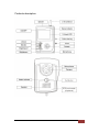
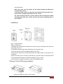
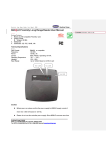
Oz-View Technical Manual V1.02 -
1st Jan 2011
2
Thank you for purchasing our professional wireless video door phone system.
Before carrying out the installation, please read this user's manual carefully and follow all
the guidelines during the process of Installation and operation.
Contents
Features 2
Components checklist 2
Products description3
Handset cradle5
Charger fixing procedure5
Button description6
ID NO. display6
Coding6
Receive code7
Code clearing8
Setting of ring tone8
Brightness adjustment8
Surveillance9
Basic operation 10
Night-vision operation11
RFID card-reader operation11
Unlocking time setting12
Installation13
Wiring of in-line PSU power adaptor13
Lock connection14
Technical specifications15
Trouble shooting16
Propagation of radio waves17
Battery specifications17
Notes18
Guarantee18
Features
● Wireless color video doorphone
● Mobile handset with 2.4 TFT-LCD screen
● Identify and screen callers
● Unlock doors remotely for visitors
● Range in free field 300 meters
● 12 selectable ringtones
● Handset to handset communication (Paging)
● Infra red camera in outside call station to see callers at night
● Expand to a 2-way system by adding a call station & handset
● Rechargeable battery via mini USB interface
● Standby status 72 hours
● Easy to install
● Built-in surveillance mode function
● Built-in back-up battery for call station (Still can work if power failure)
● Optional built-in RFID card readers
Components checklist
Package contents:
One outdoor camera/call station (Including Li-ion rechargeable battery), one handset
monitor (Including Li-ion rechargeable battery), one power adaptor for call station, one
charger for handset monitor, cradle and screws for fixing the call station on the wall.
Components description:
Handset
monitor
Charger
Call station
Power
adaptor
Cradle
Please read important information on page 16
This power adaptor is optional. You can select the in-line PSU power adaptor for
professional engineering installation. Kindly refer to page12 for details.
Oz-View Technical Manual V1.02 -
1st Jan 2011
4
Products description
Oz-View Technical Manual V1.02 -
1st Jan 2011
5
Handset cradle:
1. Desk mounted
2. Wall mounted
Oz-View Technical Manual V1.02 -
1st Jan 2011
6
Charger fixing procedure
Oz-View Technical Manual V1.02 -
1st Jan 2011
7
Button description
“ON/OFF” button: It is used to power on/power off of wireless handset monitor.
“
”: Is used to: a) answer the calls when visitors press the call button on the
outdoor call station; b) as the confirmation button when performing the ringing
tone selection; c) as the coding button when carrying out coding between the
components.
“
”: In standby status, it is used to enter the menus of ringing tone
selections; in talk status, it is used to increase brightness.
“ —”: In talk status, it is used for reducing brightness.
“
”: Is used to switch on the camera in outdoor call station in order to view
outside in standby status.
“
”: It is used to operate an electric lock release when the monitor is in the
“talking” status.
“
”: Is used to clear the previous code. After this operation, you should carry
out the coding procedure between or among the call stations and handsets
again.
“
”: Is used to set/unset the mute features.
ID NO. display
Press and hold the “ON/OFF” button when the handset monitor is in the OFF
status, until the 2.4 inch TFT-LCD displays “Welcome” and sounds two “Di
Di” tones, then release the button. It means that the handset monitor is
entering into the ON status.
Press and hold the “ON/OFF” button when the handset monitor is in ON status,
then the 2.4 inch TFT-LCD will show “Goodbye” and create two “Di Di” tones,
then release the button. This indicates that the handset monitor is entering into
OFF status.
When the outdoor camera is powered, a single “Di” tone indicates that call
station 1 is being viewed. If a dual “Di Di” tone is sounded, this confirms that
the call station 2 is being viewed.
Coding
Note: When the system is purchased as a kit, the handset and call station
have been coded together at the factory.
1).Press the “
” and “ ” buttons at the same time when the handset
monitor is in power-on status, until the screen shows the letters “Configure
code”, then release the buttons and it will enter the coding status.
2).At this time, press the call button in outdoor camera when it is in standby
status until the red indicator remains lit and creates two sounds “Di Di”, then
release the button and it will enter the coding status.
3).If the handset monitor shows the letters “success” within 8s, the coding is
Oz-View Technical Manual V1.02 -
1st Jan 2011
8
successful and the call station and handset monitor have successfully paired;
at this time, the outdoor call station will create 3 sounds “Di Di Di”. If the
handset
Monitor shows the letters "failed" within 8S, then it means that the coding is
failed and the outdoor station will have no response.
Note: After successful coding, then the outdoor camera and handset monitor
are the 1st outdoor camera and 1st handset monitor respectively; if coding is
failed, you should do the coding again.
Receive code
(Only required when adding one more call station or one more handset
monitor.)
Adding one more handset monitor:
1).Press the “
” and “
” buttons at the same time, when the 1st handset
monitor is in ON status until the screen shows “transmit code”, then release
the buttons and enter the “transmit code” status.
2).On the additional handset(2nd) after “transmit code” is displayed on the 1st
handset, press the “
” and “ ” buttons at the same time on the 2nd
handset when it is in ON status until the screen shows “receive code”, then
release the buttons and enter the “receive code” status, then press the “
”
button at this time in 2nd handset monitor. If it shows “success” on the handset,
it means that the coding has been successful.
Adding one more outdoor call station:
1).Press the “
” and “ ” buttons when the handset is in the ON status until
the screen shows “transmit code”, then release the buttons and enter the
“transmit code”status.
2).Then press and hold the call button in outdoor call station until you hear the
two “Di Di” tones. Then release the call button in outdoor call station (Do not
release until you hear the two Di Di tones). Then press the “ ” button in the
handset at this time. If it shows “success” on the handset, the coding has been
successful.
Note: After coding the 2nd call station, you should press the call button on the
2nd call station to call handset monitor to confirm and identify the ID. of the
2nd call station.
Adding one more outdoor call station and one more handset monitor:
1).Press the “
” and “ ” button when the 1st handset monitor is in ON
status until the screen shows “transmit code”, then release the buttons and
enter the “transmit code” status.
2.Then press the “
” and “ ” buttons at the same time when the 2nd
handset monitor is in ON status until the screen shows “receive code”, then
release the buttons and enter the “receive code” status. Press the “
” button
Oz-View Technical Manual V1.02 -
1st Jan 2011
9
at this time on 2nd handset monitor. If it shows “success” on the handset, then
it means that the coding is successful.
3).On the 2nd handset, press and hold the “ ” and “ ” buttons when the 2nd
handset monitor is in ON status until the screen shows “transmit code”, then
release the buttons and enter the “transmit code” status.
4).During this time, press the call button in 2nd outdoor call station until you
hear two Di Di tones. Then release the call button in the outdoor call station
(Do not release the button until you hear the two Di Di tones). If it shows
“success” in the handset, it means that the coding has been successful.
5).If all the coding is successful, press the “ ” button in the 1st handset
monitor to return to the standby status.
Note: After coding the 2nd call station, you should press the call button
on the 2nd call station to call handset monitor to confirm and identify the
ID. Of the 2nd call station.
Code clearing
Handset monitor: Keep pressing the “ ” and “
” buttons when the handset
monitor is in OFF status. At the same time, then press the ON/OFF
button in the handset monitor together until the screen displays “clear code”
and creates one “Di” sound (still keep pressing the “ ”and “ ” buttons
when you press the ON/OFF button). This means that code clearing is
successful. It will be in OFF status after releasing the buttons.
You can also press the “
” button to carry out the code-clearing.
Outdoor call station:
Press the code-clear button (the code-clear button is in the back of outdoor call
station, for details, please refer to the lock connection section. Its icon is.) and
it creates one “Di” sound. This means that code clearing is successful.
Note: Be careful when doing this, as it will cause a malfunction. You will
then need to carry out the coding procedure of outdoor call station and
handset again. See above for CODING and RECEIVE CODE sections.
Setting of ring tone
Press the “
” (ring tone selection button) when the handset monitor is in
standby status, until a ring tone sounds, the monitor is now in ring tone
selection mode. At this time, press the “
” button successively to choose
another tone (A total 12 ring tones are available for selection). After choosing
your favorite tone, press the “
” button to confirm, or wait until the playing
tone is ended, then it will auto-exit.
Oz-View Technical Manual V1.02 -
1st Jan 2011
10
Adjusting brightness
There are 6 levels for brightness adjustment
Press the “ ” button when the handset monitor is in “talking” status or
surveillance function (For details, please kindly refer to the BASIC OPERATION
and SURVEILLANCE), then the brightness level will become higher. At this time,
it will show “Val 0i” on the handset monitor (“ i ” is to indicate the brightness
level). When the brightness is adjusted up to maximum level, if you press this
button again, then it will be invalid.
Press the “
” button when the handset monitor is in “talking” status or
surveillance status, then the brightness level will become lower. At this time,
it will show “Val 0i” on the handset monitor (“ i ” is to indicate the brightness
level). When the brightness is adjusted to minimum level, if you press this
button again, then it will be invalid.
Surveillance
One to one intercom:
1).Press the “ ” button when the handset monitor is in standby status, then
the screen will display “monitoring”.
2).If the outdoor call station receives a signal within 1S, then it will display the
outdoor station; if not receiving the signal within 4S, then it will auto-exit the
monitor status.
3).In monitor status, press the “
” button again, and then it will exit the
monitoring of outdoor call station. The monitor time is 60S. After 60S, it will
auto-exit the monitor status.
One to two or two to two system:
1).Press the “
” button when the handset monitor is in standby status, then it
will monitor the 1st outdoor station (It will display “monitoring 01”); press this
“
” button again, then it will monitor the 2nd outdoor station (It will display
“monitoring 02”); press the “
” button in third time, it will auto-exit the
monitoring status.
2).If receiving a signal within 1S, then it will monitor the outdoor station; if not
receiving the signal within 4S, then it will auto-exit the monitor status.
3).In standby status, press the “ ” button to start or end the monitoring of
outdoor stations. After 60S, it will auto-exit the status.
Basic operation
One to one intercom:
1).In standby status, when a visitor presses the call button on call station, then
the power indicator will still light.
2).a. If not receiving a response signal within 4S, then it will sound “Di Di Di Di”,
Oz-View Technical Manual V1.02 -
1st Jan 2011
11
and it will end the call status and return to the standby status.
b. If receiving a response signal, the handset will display “talking” and the
outdoor station will still sound “Du Du”, then the power indicators of handset/s
will light and play the selected ring tone/s; meanwhile the TFT-LCD will display
the visitor’s image.
3).a. If no one answers the call; the call will last 60S and return to the standby
status.
” buttons, then it will stop playing the ring
b. If some one presses the “
tone and enter the “talking” status (The indicators in handset monitors will turn
from red to green and stay lit), the talk time is 120S.
4).In the “talking” mode, pressing the “
” button will operate the relay at the
call station which can be connected to operate an electric lock release and
allow the visitors enter, the monitor will display “unlock” (If visibility is poor,
pressing the “ ” button will activate the night-vision of outdoor camera ).
5).In “talking” mode, the user can press the “
” button again to end the
communication, and then handset monitor will enter the standby status after
sounding two “Du Du” tones.
One to two intercom:
1). In standby status, when the visitors press the call button on call station, then
the power indicators will light.
2).a. If not receiving a response signal within 4S, then it will sound “Di Di Di Di”,
and end the call status and return to the standby status.
b. If receiving a response signal from any handset monitors, then the
handset will display “talking” and the outdoor call station will still sound “Du Du”.
Then the power indicators of handset will remain lit and play the selected ring
tone; meanwhile the TFT-LCD will display the visitor’s image.
3).a. If no one answers the call, the call will last 60S and return to the standby
status.
b. If some one presses the “ ” button from any handsets, then it will stop
playing the ringtone and enter the talk status (the indicator in handset will turn
from red to green and remain lit), the talk time is 120S, while the 2nd handset
will return back to standby status after creating one “ Di ” sound.
4).In the process of talking, pressing the “
” button will operate the relay and
allow the visitors to enter, the monitor will display “unlock” (pressing the “
button will activate the night-vision of outdoor camera).
”
5).In the process of talking, the user can press the “ ” button again to end the
communication, and then it will enter the standby status after sounding two “Du
Du” tones.
Handset intercom (Paging):
1).In standby status, if the user presses the “ ” in one handset monitor, then
the red indicators will light and enter the call status. The screen will display
Oz-View Technical Manual V1.02 -
1st Jan 2011
12
“talking”.
2).a. If there is no response signal with 4S from called handset monitor, after 4
“Di Di Di Di” tones, the handset will exit the call status and return to standby
status.
b. If receiving a response signal with 4S from the called handset monitor,
then the calling handset monitor will play the selected ring tone, then the called
handset will display “talking” and play its selected ring tone. The indicator light
will remain lit.
3). a. If no one answers the call from called handset monitor, the call will last
60S and enter to the standby status.
b. If some one answers the call from called handset monitor, then it will stop
playing the ring tone and enter the “Talking” status (the indicators in both
handset monitors will turn from red to green and remain lit), the talk time is
120S.
c. Meanwhile, if pressing the “
” button in calling handset monitor, then it
will end the call and enter into the standby status.
4).In the process of paging, the user can press the “
” button again in any
handset monitors to end the communication, then it will enter the standby status
after hearing two “Du Du”.
Note: If the handset monitor is short of power, then it will indicate the user to
charge the battery in handset monitor.
Night-vision operation
1). When the handset is in talking status, press the “
night-vision of outdoor camera.
” button to activate the
2). When the handset is in surveillance status, press the “
activate the night-vision of outdoor camera.
” button to
RFID card-reader operation:
It is used to register two management cards (one is to add cards, one is to
delete cards), 20pcs user cards and 20pcs shadow cards; being compatible
with EM4001;
Initialization: Which is used to set 2pcs management cards (one is to add cards,
one is to delete cards) and 20pcs shadow cards (The exact cards depend on
the client’s request, maximum 20pcs users' cards).
Initialization procedure: Press the Initialization button within the battery
cover, then it will buzz and the red indicator will flash. In initialization status, the
operation procedures as followings: contact【Add cards】→【Delete cards】→
【Shadow cards 1】【Shadow cards 20】,then all the user cards will be deleted.
During this period, if you press the initialization button again or wait for 30S
Oz-View Technical Manual V1.02 -
1st Jan 2011
13
without any operations, and then it will auto-exit the status.
If not doing any operations after entering the initialization status, then it will not
delete the previous cards records.
Note: If you lose the【
【management cards】
】or【
【shadow cards】
】, please do
the above operation to initialize and then re-add the【users' cards】
】, Please
kindly make the good marks on all the cards to differentiate.
Add user cards: Which is used to add the user card.
Add cards procedure: In standby status, contact【Add-cards】, then it will
buzz twice and the green indicator will flash. In add card status, the operation
procedure as followings: contact【Shadow cards 1】→【User cards 1】, then
shadow cards and user cards correspondingly, until up to【Shadow cards 20】
→【User cards 20】, please mark them well on the shadow cards and user
cards .During this period, if you contact the add cards again, and then it will
auto-exit the status.
Note: You can only add the cards in the name of adding cards and shadow
cards which had been authorized in initialization status.
Delete user cards: which is used to delete the user cards.
Delete cards procedure: In standby status, contact the 【Delete cards】,
then it will buzz once and the red indicator will flash. In delete-card status, the
operation procedure as followings: Contact 【 shadow cards 】 (that is
corresponding to the user cards), then it will delete the user cards. During this
period, if you contact the delete cards again, and then it will auto-exit the status.
Note: After deleting the user cards, then you should re-add the new user
cards according to the section of ADD USER CARDS.
Cards unlocking: In standby status, contact the valid user cards, then it will
unlock the doors.
Note: Only the valid user cards can unlock the doors, it indicated that it
will buzz twice and the green indicator will flash twice. If it is the invalid
cards, then it will buzz once and the red indicator will flash once.
Unlocking time setting
1).The 1st unlocking time is 1.8S (In default status, this is the 1st unlocking
method). With power disconnected from the call station, press and hold the call
button in outdoor call station, at this time connect the power to call station, when
the unit sounds a single “Di” tone, release the call button and the unlocking time
will now be set at 1.8 seconds.
2).The 2nd unlocking time is 4S. With power disconnected, press and hold the
call button on call station, and connect power to this call station. When you hear
two “Di Di” tones, release the call button and the unlocking period will be set at
4 seconds.
3). The 3rd unlocking time is 8S. With power disconnected, press and hold the
call button on call station, and connect power to the call station. When you hear
three “Di Di Di” tones, release the call button and the unlocking period will be
Oz-View Technical Manual V1.02 -
1st Jan 2011
14
set at 8 seconds.
Note: The users can only unlock for the visitors during the talking and
communication mode.
In communication status, if either part is powered-off, then the other will
return back to standby status after one “Di” sound.
The 1.8S unlocking time has 2 pulses, while the 4S unlocking time and 8S
unlocking time have only 1 pulse. Choose the proper unlocking time as
your request.
Installation
Step 1: Install the back
Step 2: Install panel
1).Release the call station from back box by removing the locking screw under the
front edge of the unit.
2).Drill proper wire-through holes according to the mounting units.
3).Use four screws to fix the installation panel on the wall.
4).Connect the cables from wire-through holes and square holes of rear panel in the
call station.
(When an electric lock is not being connected, any unused cables or terminals should
be protected and insulated to avoid the possibility of short circuits)
5).Use screws to fix the door station on the rear installation panel.
Wiring of in-line PSU power adaptor
1).Check and keep the power in OFF status.
Oz-View Technical Manual V1.02 -
1st Jan 2011
15
2).Open the front cover of call station power adapter.
3).Connecting the AC line to AC INPUT terminal and DC line to DC OUTPUT
terminal. (be careful of the AC. DC terminal to avoid of wrong connection)
4).Cover the front cover of call station
Lock connection
Oz-View Technical Manual V1.02 -
1st Jan 2011
16
Technical specifications
Oz-View Technical Manual V1.02 -
1st Jan 2011
17
Trouble shooting
Oz-View Technical Manual V1.02 -
1st Jan 2011
18
Propagation of radio waves
The radio coverage quality, and therefore the performance of the doorphone,
may be altered by obstacles located between the door station and the interior
handset unit: walls, partitions, slabs, armored doors or lift shaft comprising
metallic components.
(Furthermore, radio coverage may also be affected by electrical or
electromagnetic interference).
It is important to test the radio range on the installation site.
Battery specifications:
The above marked time is in the specific situation and atmosphere
Use the authorized charger only
Do not disassemble the batteries
Do not short -circuit the batteries
Do not expose the batteries to extreme hear, fire or water
Oz-View Technical Manual V1.02 -
1st Jan 2011
19
Notes
1).Handset monitors should be situated away from heat sources and water.
2).Products should be opened only by the professional personnel. If there is a
malfunction please contact us or our agents.
3).Handset monitors should be located where there is a good ventilation, dry,
dustless and not in direct sunlight. Don’t use the chemical impregnated or wet
cloth to clean the products. Clean, soft, dry cloth can be used to clean the
products.
4).Please install the products according to this instruction manual to avoid of
damaging to the products.
Guarantee
One-year warranty.
Oz-View Technical Manual V1.02 -
1st Jan 2011
20