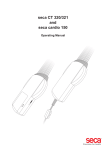
1
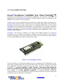
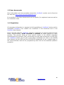
uIceBlue 2 Wireless embedded control module GETTING STARTED MANUAL uIceBlue2 Wireless control module
© emxys 2008
All rights reserved
emxys reserves the right to make changes and improvements
to its products without providing notice.
uIceBlue, uIceBlue2, IceBlue and PearlBlue are trademarks of emxys Ltd.
Version 2.0 July 2009
2
www.emxys.com
[email protected]
Table of Contents
1. Introduction and overview. ................................................................................ 6 1.1. The Bluetooth technology. ............................................................................ 6 1.2. The uIceBlue2 Module. ................................................................................. 7 1.3 hola ............................................................................................................... 8 1.4. Requisites. .................................................................................................... 8 2. Connecting uIceBlue2....................................................................................... 10 2.1. Wireless connection. ................................................................................... 10 2.2. ICD2 Connection. ........................................................................................ 13 2.3. Power requirements. .................................................................................. 16 3. Programming uIceBlue2. .................................................................................. 18 3.1. Programming the module with ICD2. .......................................................... 18 4. Pin assignments. .............................................................................................. 20 4.1. Pin Out........................................................................................................ 20 3
www.emxys.com
[email protected]
Index of Figures
Figure
Figure
Figure
Figure
Figure
Figure
Figure
Figure
Figure
Figure
Figure
Figure
1. The uIceBlue2 module. ............................................................................ 7
2. Bluetooth network with uIceBlue2 ........................................................ 11
3. Windows Device Discovery wizard ........................................................ 12
4. Pin code requirement ............................................................................ 12
5. Entering PIN code to pair the device ..................................................... 12
6. Docklight Serial Terminal screenshot..................................................... 13
7. ICD2 connection scheme ....................................................................... 14
8. ICD2 Programming & Debug port pin-out .............................................. 14
9 . MPLAB IDE environment with an opened project .................................. 18
10. uIceBlue2 Layout ................................................................................. 20
11. uIceBlue2 Internal diagram ................................................................. 21
12. Pin-Out Distribution ............................................................................. 22
4
www.emxys.com
[email protected]
Index of Tables
Table 1. uIceBlue2 main Specifications. ............................................................... 16
Table 2. uIceBlue2 Pin Out. .................................................................................. 22
5
www.emxys.com
[email protected]
1. Introduction and overview.
Bluetooth is a wireless communication protocol conceived to enable high speed
data transfer through portable devices. Its physical layer can be implemented
as a light weight, small, inexpensive and low power electronic device and
therefore is being mainly used for handheld computers and phones within the
consumer electronics market. However, its applications within embedded
systems are countless and twofold: on one side, Bluetooth enabled embedded
systems may communicate with handheld devices extending its capabilities to
supervision, control and data acquisition; on other side, embedded systems
may communicate between them easily, at high data rates and at low cost up
to 100 meters in distance and even more1.
uIceBlue2 module, an evolution of mature uIceBlue, enables the integration of
Bluetooth communications within embedded systems fast, easily and
effectively. This document provides the information to start with quick hands
on practice.
1.1. The Bluetooth technology.
Bluetooth is an open specification2 to provide short-range wireless communications.
It operates in the unlicensed ISM band at 2.45 GHz using Frequency Hop Spread
Spectrum modulation to avoid interference. There are two kind of devices: Class 2
devices reach up to 10 m with a power of 0 dBm; Class 1 devices reach up to 100
m with 20 dBm1.
Bluetooth communicates a master and a slave device. Usually each device is able to
operate as either master or slave at a time. Bluetooth devices have a unique 48-bit
address (BD_ADDR) used as identification. This address defines also the way
devices negotiate and start radio communication.
The Bluetooth specification defines the implementation of profiles that run over
lower layers of the Bluetooth stack. Bluetooth Profiles define a simple way to
communicate different devices using a high level protocol. Among several Bluetooth
profiles the Serial Port Profile was created to make a simple wireless substitution to
the RS232 cable that connects many computers and embedded products. The final
goal of Bluetooth was to create a low cost alternative to the wire connection.
1
Although Class 1 Bluetooth
can be extended with the use
this area.
2
The complete Bluetooth
www.bluetooth.com.
For beginners a good starting
devices are specified to reach distances of up to 100 m, this
of directional antennas. Contact emxys for specific solutions in
(more than 1000 pages) specification cab be found at
point is http://en.wikipedia.org/wiki/Bluetooth.
6
www.emxys.com
[email protected]
1.2. The uIceBlue2 Module.
The uIceBlue2 module is an embeddable control module based on the USB
featured microcontroller PIC18F4550 from Arizona Microchip™. To
implement the Bluetooth communication capabilities, the module contains a full
featured core of the PearlBlue module on the same board, which is connected to the
USART pins of the PIC microcontroller.
PearlBlue core device implements the Serial Port Profile and allows simple point to
point wireless communication of devices that incorporate this profile over Bluetooth.
PearlBlue connects the radio serial port to a physical UART that can be easily
interfaced to an embedded microcontroller, microprocessor or computer. Moreover,
PearlBlue can work on its own and offer 6 general purpose input/output pins. For a
detailed information about the PearlBlue operation and capabilities, refer to the
PearlBlue User Manual.
PearlBlue, may act as a master or an slave; This feature allows it to wait for
connections or to initiate a connection. Therefore, the full power of the PearlBlue
module is available in this device both from the air side and from the serial channel
(in this case available for the microcontroller code).
Figure 1. The uIceBlue2 module.
The board offers in a DIP-style double row pin connector the PIC18F4550 pin out,
with some exceptions like the clock and power pins. This allow to implement almost
any application intended previously for this MCU with no constrain, with the
advantage of having together a USB interface combined with Bluetooth
serial communications included with no glue code or electronics required.
This results in a true glueless solution to embed Wireless Bluetooth
communications in any equipment or electronic device with the minimum effort and
investment, and a maximum of efficiency.
7
www.emxys.com
[email protected]
1.3 User documents
More information and documentation about the uIceBlue2 module can be found at
the web site http://www.wirelessembedded.com.
It is possible to find free documents for all the public, for registered users as well as
for customers users.
1.4. Requisites.
All necessary information to operate the full capabilities of uIceBlue2 device and its
embedded PearlBlue core module are contained in this document and in the
PearlBlue User Manual.
Due to the fact that the uIceBlue2 module is powered by an Arizona Microchip PIC
family Microcontroller, some expertise is needed on these devices to start
working. This manual refers to some specific details of the MPLAB integrated
Development Environment (IDE) concerning the tools and procedures to work with
the uIceBlue2 board, but to get a more basic knowledge we refer to the MPLAB
User Manual (for the IDE) and the PIC18F4550 datasheets for an in-depth study of
the microcontroller both at the programming level and at the hardware platform
operation.
8
www.emxys.com
[email protected]
9
www.emxys.com
[email protected]
2. Connecting uIceBlue2.
uIceBlue2 module enables the integration of Bluetooth communications within
embedded systems fast, easily and effectively. In this chapter we will review
the basic procedures to initiate the connection from and to the uIceBlue2
module with a remote device via Bluetooth and also how to program the
microcontroller and how to initiate an In Circuit Debug session with the
Arizona Microchip™ ICD2 debugger.
2.1. Wireless connection.
One of the main advantages of the Bluetooth wireless link is its plug and play
feature. The current operating systems (running laptops, PDA’s, mobile phones, ...)
implement these functions as a part of the software drivers designed for Bluetooth
adapters such as USB dongles, PCI or PCMCIA cards and more.
The PearlBlue proprietary firmware is not an exception to this, and incorporates all
the software procedures needed to enter on an existing Bluetooth network, discover
available devices, initiate a link, etc.
The uIceBlue2 has the embedded PearlBlue core module configured as a Serial
bridge and ready to be discovered by other Bluetooth devices by default. For this
working mode to be possible, the uIceBlue2 pin PIO7 must be open or at low state.
When pin PIO7 is set, this serial bridge mode is disabled, and the PearlBlue module
enters in Command mode. Please refer to PearlBlue Manual for more information
about this operation mode.
In order to make a first approach to the uIceBlue2 Bluetooth communication, lets
suppose we have a set of devices like the following:
-
A computer with Windows XP SP23.
A USB to Bluetooth dongle connected to the computer (we use the
Conceptronic™ CBT100U dongle as a reference).
An uIceBlue2 Module in a target board that powers it at 3.3 V
Other Bluetooth devices (optional) (we use a Nokia S60
smartphones and an iPaq Pocket PC).
3
Other platforms differ in the way the connection is achieved but the procedure involved is
similar.
10
www.emxys.com
[email protected]
Figure 2. Bluetooth network with uIceBlue2
1. Connect a power supply to the target board where the uIceBlue2 module is
placed and enable the Bluetooth on the other devices you may have.
uIceBlue2’s default start condition is being discoverable The PIO.7 input pin
has to be at low state to be able to activate the USART connection (see
below at point 4 and PearlBlue Manual for more information about PIO.7
operation).
2. Open the Windows Bluetooth devices manager by clicking twice on the icon
at the system tray or into the Control Panel.
3. Click Add device and Next. Windows will try to detect the devices around.
4. You will see a window showing the Bluetooth devices discovered. uIceBlue2
should be among them. By right clicking on any of them you can see its
Bluetooth address.
11
www.emxys.com
[email protected]
Figure 3. Windows Device Discovery wizard
In this state, if you double click the device you will be able to discover the services
available, which in this case, will be the serial port.
If it is the first time you access to the device, you will be asked to PAIR the board.
Figure 4. Pin code requirement
This consists on an acknowledgement operation to improve the safety in a network
highly exposed to intrusion (like the Wireless based ones). By default, the asked
key for uIceBlue2 is set as “1111”. Entering this code when required will set the
Bluetooth serial port icon highlighted, showing that the virtual COM port is ready to
communicate, and also, the software COM number associated to it.
Figure 5. Entering PIN code to pair the device
It is important to mention that the steps above can appear in a different order
depending on the Operating System and the Bluetooth driver version we are using.
Perhaps we are required to enter the PIN code in the moment we ask for the
available services. In this case, we should receive the services (virtual COM ports)
directly after the paring process.
In the case that two COM ports appear, they should be labelled as output and input
serial ports. Those COM resources are assigned by the Operating system depending
on which device initiated the link. In our case, the requirement was sent from the
Windows™ drivers, therefore, the communication will be carried out through the
output serial port.
12
www.emxys.com
[email protected]
After this point, we can try to connect the uIceBlue2 by means of this virtual COM
port through any serial communication program like WindowsTM Hyperterminal or
the GNU software DockLight.
Figure 6. Docklight Serial Terminal screenshot
2.2. ICD2 Connection.
Aside of tools intended to connect and operate the device via Bluetooth wireless
connection by means of the virtual COM port service provided by the embedded
PearlBlue core, some resources are needed to develop the software for the PIC
microcontroller and to program it with the resulting binary files.
For this purpose, we propose as the ideal solution a complete development tool
consisting on:
1. The uIceBlue2 module + target board.
2. ICD2 In-Circuit debugger from Arizona Microchip™.
3. MPLAB Integrated Development Environment (IDE) from Arizona
Microchip™.
The ICD2 is the latest In-Circuit debugger developed by the PIC manufacturer
which enables the possibility to run in-circuit debugging over the uIceBlue2-based
target board. This consists in to have the uIceBlue2 connected to the ICD2 through
the PIC ICSP pins present at uIceBlue2 pin-out by one side, and a computer
running the MPLAB IDE connected to the other side to the ICD2 USB or Serial port.
The program designed to run on the PIC18F4550 microcontroller is debugged
directly on its final platform (in this case, the uIceBlue2 device), but showing online the execution of the code in the simulator included in MPLAB environment in
several formats (line-by-line, animation, etc.) and also the contents and variations
of the Special Function Register (SFR) values.
13
www.emxys.com
[email protected]
Therefore, the capabilities available are those which are familiar at the MPLAB
simulator (animation, simultaneous code inspection and SFR changes, and so on)
but with extended features including the operation of USART and AD conversion.
Figure 7. ICD2 connection scheme
In the image above we can appreciate the connection scheme of the development
system composed by the devices mentioned. It is important to refer to the user to
the documentation included in the ICD2 package, which mentions several
connection modes. Which we depict here is the USB connection with the PC
platform running the MPLAB IDE. No power is needed in this case to supply the
ICD2 device. Although power is required to apply to the target. This is motivated to
the internal configuration of the logical drivers for programming pins inside ICD2,
being supplied from the external side as a requisite.
Figure 8. ICD2 Programming & Debug port pin-out
14
www.emxys.com
[email protected]
In the figure above a layout of ICD2 programming & Debug port pin out is depicted
for more information, these programming/debug pins can be found at uIceBlue2
pin-out as directly accessible PIC pins. As it was mentioned, we refer to the ICD2
documentation for further details.
15
www.emxys.com
[email protected]
2.3. Power requirements.
Although the uIceBlue2 comes with integrated input low-drop out series voltage
regulators to power the electronics inside, some limits exist in its operation, shown
in the following table.
Some of them are maximum rating parameters, so special emphasis is made in the
fact that those limits must be carefully observed in any working condition, and in
other case, special care must be taken in the case that these parameters could
trespass the limitations.
Table 1. uIceBlue2 main Specifications.
Specification
Data
Power supply
+ 3,6 ± 0.1V DC
Maximum Rating Vcc = + 12 V DC
(Vcc limited by included LDO regulator)
Current consumption
150 mA maximum
Internal Operation
Voltage
IO digital Pin voltage /
sink/supply current
Analog input: voltage
range
Analog input:
impedance
Input
+ 3.3 V
3.3 V / 20 mA (maximum)
0 to + 3.3 V ± 0,8 V (Vref+=Vdd, Vref-=Vss)
Zin < 10 KΩ
Size
54,3 x 26,2 mm
Environmental
-40oC to +70oC, 5-95% humidity non condensing
Carrier Frequency
2402 MHz to 2480 MHz
Radio Power
14 dBm (Class 1)
16
www.emxys.com
[email protected]
17
www.emxys.com
[email protected]
3. Programming uIceBlue2.
uIceBlue2 module enables fast prototyping and development by means of the
integrated capabilities of In-Circuit programming and In-Circuit Debugging
offered by the family of Flash PIC microcontrollers.
We propose as the perfect combination to develop complete embedded
solutions based on uIceBlue2 modules the development system composed by
the Microchip™ MPLAB Integrated Development Environment (IDE) that can
be downloaded from Microchip web page, and the ICD2 In-Circuit debugger
from the same manufacturer (this device has to be purchased separately from
Microchip).
3.1. Programming the module with ICD2.
Once we have configured our MPLAB IDE to work with ICD2 as a programmer &
Debugger device (this is possible in the moment of the project creation or at the
menu Programmer → Select Programmer → MPLAB ICD 2) we have to connect to
it by means of Programmer → Connect.
Once we succeed, the only remaining step is to have some binary (.HEX file) at the
project or to build successfully a new one pressing Project → Build all, and
download the firmware to the microcontroller with the menu command Programmer
→ Program. This last option must appear when the Connect operation gets success.
Figure 9 . MPLAB IDE environment with an opened project
18
www.emxys.com
[email protected]
19
www.emxys.com
[email protected]
4. Pin assignments.
uIceBlue2 module offers a direct 3.3V digital interface to external logic
components to quickly implement embedded control devices.
The (almost) complete PIC18F4550 pin out is available at a DIP style double
row 2,54 mm pitch pin-out in order to get an easy and cheap way to connect
the part to a custom board or a breadboard for fast prototyping purposes.
In addition, the uIceBlue2 pin-out is provided with some additional service
pins to allow access to the embedded Pearlblue core device for programming
purposes and with a direct Mini USB connector that enables immediate Full
speed USB connectivity to USB master devices (like computers).
4.1. Pin Out.
The scheme below shows a layout of the uIceBlue2 device.
PearlBlue
PIC18F4550
USB Led
USB Power
connection
resistance
Mini USB Connector
Figure 10. uIceBlue2 Layout
20
www.emxys.com
[email protected]
As depicted below, internally the uIceBlue2 consists on a PIC18F4550 connected via
USART interface with the PearlBlue Bluetooth module. The power input of the
uIceBlue2 is connected to the USB power input via the Shunt resistor. This way, no
external power supply is needed if the uIceBlue2 is going to be used connected to
USB, getting the power from there.
PIN #37 (USB D‐)
PIN #38 (USB D+)
USB Power
USART Tx
LED
GND
R shunt
PIN #2 Vcc
PIC18F4550
GND
LDO
Regulator
3,3V
LDO
Regulator
3,3V
USART Rx
PearlBlue
Bluetooth
Module
Figure 11. uIceBlue2 Internal diagram
CAUTION :
If an external power supply has to exist connected simultaneously with
USB connection, extra precautions has to be observed in order to limit the
power drawing from USB port either limiting the current sourced from USB
or removing the shunt resistance to get the power only from the external
DC source.
The pin-out includes the (almost) complete pin out of the PIC18F4550
microcontroller, plus some additional pins from the embedded Pearlblue core. It is
implemented by a two rows DIP style 2.54 mm pitch footprint, making easy and
cheap to integrate the module both in custom PCB cards and in breadboards
available in the market. The improved electrical configuration of the IO pins at the
microcontroller PIC18F4550 allows to interface directly these pins to higher loading
components like BJT-based adapting circuits, leds, buzzers, drivers, etc. Making the
module more flexible and robust and also more easy to apply.
21
www.emxys.com
[email protected]
Figure 12. Pin-Out Distribution
In the table below, a complete description of Pin Out is included:
Table 2. uIceBlue2 Pin Out.
No.
1
2
3
Symbol
GND
Vcc
RB0
I/O
Power
Power
I/O
4
5
6
7
8
RB1
RB2
RB3
RB4
RB5
I/O
I/O
I/O
I/O
I/O
Description
Ground (0 V)
Vcc Pin from auxiliary power (+12V>Vcc>+ 3.3V)
1
MCU Pin8 RB0/INT/AN12/INT0/FLT0/SDI/SDA:
Digital IO/Analog I
1
MCU Pin 9 RB1/AN10/INT1 :Digital IO/Analog I
1
MCU Pin 10 RB2/AN8 :Digital IO/Analog I
1
MCU Pin 11 RB3/AN9/CCP2 :Digital IO/Analog I
1
MCU Pin 14 RB4/AN11/KBI0 :Digital IO/Analog I
1
MCU Pin 15 RB5/KBI1/PGM :Digital IO
22
www.emxys.com
[email protected]
9
10
11
RB6
RB7
/MCLR
I/O
I/O
Reset
12
13
14
15
16
17
RA0
RA1
RA2
RA3
RA4
RA5
I/O
I/O
I/O
I/O
I/O
I/O
18
19
20
21
22
23
RE0
SPI_CSB
SPI_MISO
RESET
SPI_MOSI
PIO.7
I/O
SPI
SPI
Reset
SPI
I/O
24
25
26
27
28
29
SPI_CLS
RC7
RC6
RC0
RE2
RE1
SPI
I/O
I/O
I/O
I/O
I/O
30
31
32
33
34
35
36
37
38
39
40
41
42
RC1
RC2
VUSB
RD0
RD1
RD2
RD3
RC4
RC5
RD4
RD5
RD6
RD7
I/O
I/O
Power
I/O
I/O
I/O
I/O
I/O
I/O
I/O
I/O
I/O
I/O
1,2
MCU Pin 16 RB6/PGC/KBI2 :Digital IO
MCU Pin 17 RB7/KBI3/PGD :Digital IO
2
MCU Pin 18 Master Clear (Reset), Vpp
Programming voltage input, RE3
1,3
MCU Pin 19 RA0/AN0 :Digital IO/Analog I
1,3
MCU Pin 20 RA1/AN1 :Digital IO/Analog I
1,3
MCU Pin 21 RA2/AN2/Vref- :Digital IO/Analog I
1,3
MCU Pin 22 RA3/AN3/Vref+ :Digital IO/Analog I
1
MCU Pin 23 RA4/T0CKI/C1OUT/RCV :Digital IO
1,3
MCU Pin 24 RA5/AN4/SS/HLVDIN :Digital
IO/Analog I
1,3
MCU Pin 25 RE0/AN5/CK1SSP:Digital IO/Analog I
SPI CSB line for module module
SPI ISO line for Bluetooth module
PearlBlue RESET pin
SPI MOSI line for Bluetooth module
4
1 SPP UART connection off, return to command
mode
0 Bluetooth Serial port (SPP) in UART connection
active after BTCOM: D2UART command
SPI Clock line for Bluetooth module
1
MCU Pin 1 RC7/RX/DT :Digital IO
1
MCU Pin 44 RC6/TX/CK :Digital IO
1
MCU Pin 32 RC0/T1OSO:Digital IO
1,3
MCU Pin 27 RE2/AN7/OESPP :Digital IO/Analog I
1,3
MCU Pin 26 RE1/AN6/CK2SPP :Digital IO /
Analog I
1
MCU Pin 35 RC1/T1OSI/CCP2 :Digital IO
1
MCU Pin 36 RC2/CCP1/P1A :Digital IO
1
MCU Pin 37 VUSB
1
MCU Pin 38 RD0/SPP0 :Digital IO
1
MCU Pin 39 RD1/SPP1 :Digital IO
1
MCU Pin 40 RD2/SPP2 :Digital IO
1
MCU Pin 41 RD3/SPP3 :Digital IO
1
MCU Pin 42 RC4/D-/VM :Digital IO
1
MCU Pin 43 RC5/D+/VP :Digital IO
1
MCU Pin 2 RD4/SPP4 :Digital IO
1
MCU Pin 3 RD5/SPP5/P1B :Digital IO
1
MCU Pin 4 RD6/SPP6/P1C :Digital IO
1
MCU Pin 5 RD7/SPP7/P1D :Digital IO
1,2
23
www.emxys.com
[email protected]
Notes:
1
2
3
4
Refer to Arizona Microchip™ Datasheet for microcontroller family
PIC18F4550 for further information.
Programming pins also present at ICD Debug & Programming
connector.
Refer to Arizona Microchip™ Datasheet and Mid-Range Manual for
microcontroller family PIC18F4550 for further information about the
electrical requirements for those pins.
The PIO.7 pin is described at “PearlBlue Getting Started Manual” as a
key pin to operate the transparent USART SSP (Serial port profile )
mode among any PearlBlue-core based devices (like uIceBlue and
uIceBlue2) and other Bluetooth parts that include the SPP as an
available service. This mode allows to establish a connection across
Bluetooth SPP virtual COM port service (in a host computer, for
example) and the USART pin-out of PearlBlue-core device (i.e. USART
pins at PIC18F4550 micro), or between two PearlBlue-core based
devices, in a transparent mode as if a virtual serial direct cable is
connected. For this operation mode, please refer to “PearlBlue Getting
Started Manual” for more information.
24
www.emxys.com
[email protected]