1
Machine Automation Controller
NJ-series
TM
CPU Unit Built-in EtherNet/IP Port
User’s Manual
NJ501-15@@
NJ501-14@@
NJ501-13@@
NJ301-12@@
NJ301-11@@
CPU Unit
W506-E1-08
© OMRON, 2011
All rights reserved. No part of this publication may be reproduced, stored in a retrieval system, or transmitted, in any form, or
by any means, mechanical, electronic, photocopying, recording, or otherwise, without the prior written permission of
OMRON.
No patent liability is assumed with respect to the use of the information contained herein. Moreover, because OMRON is
constantly striving to improve its high-quality products, the information contained in this manual is subject to change without
notice. Every precaution has been taken in the preparation of this manual. Nevertheless, OMRON assumes no responsibility
for errors or omissions. Neither is any liability assumed for damages resulting from the use of the information contained in
this publication.
Trademarks
• Sysmac and SYSMAC are trademarks or registered trademarks of OMRON Corporation in Japan and other
countries for OMRON factory automation products.
• Windows, Windows XP, Windows Vista, Windows 7, and Windows 8 are registered trademarks of Microsoft
Corporation in the USA and other countries.
• EtherCAT® is registered trademark and patented technology, licensed by Beckhoff Automation GmbH, Germany.
• ODVA, CIP, CompoNet, DeviceNet, and EtherNet/IP are trademarks of ODVA.
• The SD and SDHC logos are trademarks of SD-3C, LLC.
Other company names and product names in this document are the trademarks or registered trademarks of their
respective companies.
Introduction
Introduction
Thank you for purchasing an NJ-series CPU Unit.
This manual contains information that is necessary to use the NJ-series CPU Unit. Please read this
manual and make sure you understand the functionality and performance of the NJ-series CPU Unit
before you attempt to use it in a control system.
Keep this manual in a safe place where it will be available for reference during operation.
Intended Audience
This manual is intended for the following personnel, who must also have knowledge of electrical systems (an electrical engineer or the equivalent).
• Personnel in charge of introducing FA systems.
• Personnel in charge of designing FA systems.
• Personnel in charge of installing and maintaining FA systems.
• Personnel in charge of managing FA systems and facilities.
For programming, this manual is intended for personnel who understand the programming language
specifications in international standard IEC 61131-3 or Japanese standard JIS B 3503.
Applicable Products
This manual covers the following products.
• NJ-series CPU Units
• NJ501-15@@
• NJ501-14@@
• NJ501-13@@
• NJ301-12@@
• NJ301-11@@
Part of the specifications and restrictions for the CPU Units are given in other manuals. Refer to Relevant Manuals on page 2 and Related Manuals on page 23.
NJ-series CPU Unit Built-in EtherNet/IP Port User’s Manual (W506)
1
Relevant Manuals
Relevant Manuals
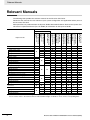
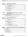
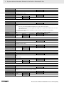
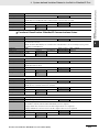
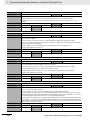
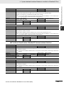
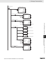
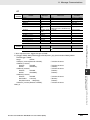
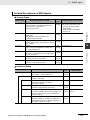
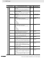
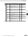
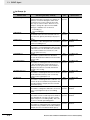
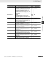
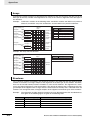
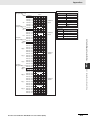
The following table provides the relevant manuals for the NJ-series CPU Units.
Read all of the manuals that are relevant to your system configuration and application before you use
the NJ-series CPU Unit.
Most operations are performed from the Sysmac Studio Automation Software. Refer to the Sysmac Studio Version 1 Operation Manual (Cat. No. W504) for information on the Sysmac Studio.
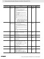
Manual
Basic information
NJ-series Troubleshooting Manual
NJ-series Database
Connection CPU Unit
User’s Manual
NJ-series CPU Unit
Built-in EtherNet/IP
Port User’s Manual
NJ-series CPU Unit
Built-in EtherCAT Port
User’s Manual
NJ-series Motion
Control Instructions
Reference Manual
NJ-series CPU Unit
Motion Control User’s
Manual
NJ-series Instructions
Reference Manual
NJ-series CPU Unit
Software User’s
Manual
Introduction to NJ-series Controllers
NJ-series CPU Unit
Hardware User’s
Manual
Purpose of use
Setting devices and hardware
Using motion control
Using EtherCAT
Using EtherNet/IP
Using the database connection service
Software settings
Using motion control
Using EtherCAT
Using EtherNet/IP
Using the database connection service
Writing the user program
Using motion control
Using EtherCAT
Using EtherNet/IP
Using the database connection service
Programming error processing
Testing operation and debugging
Using motion control
Using EtherCAT
Using EtherNet/IP
Using the database connection service
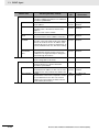
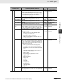
Learning about error management and
corrections*1
Maintenance
Using motion control
Using EtherCAT
Using EtherNet/IP
*1 Refer to the NJ-series Troubleshooting Manual (Cat. No. W503) for the error management concepts and an overview of
the error items. Refer to the manuals that are indicated with triangles for details on errors for the corresponding Units.
2
NJ-series CPU Unit Built-in EtherNet/IP Port User’s Manual (W506)
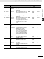
Manual Structure
Manual Structure
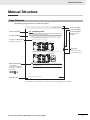
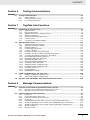
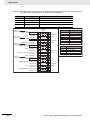
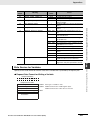
Page Structure
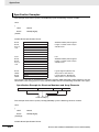
The following page structure is used in this manual.
Mounting Units
Level 1 heading
Level 2 heading
Level 3 heading
Connecting Controller Components
Gives the current
headings.
4 Installation and Wiring
Level 2 heading
Level 3 heading
4-3
4-3-1
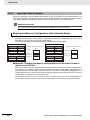
The Units that make up an NJ-series Controller can be connected simply by pressing the Units together
and locking the sliders by moving them toward the back of the Units. The End Cover is connected in the
same way to the Unit on the far right side of the Controller.
A step in a procedure
1
Join the Units so that the connectors fit exactly.
Hook
Indicates a procedure.
Hook holes
Connector
4-3 Mounting Units
4
The yellow sliders at the top and bottom of each Unit lock the Units together. Move the sliders
toward the back of the Units as shown below until they click into place.
Move the sliders toward the back
until they lock into place.
Lock
Release
Slider
Special information
Icons indicate
precautions, additional
information, or reference
information.
Manual name
4-3-1 Connecting Controller Components
2
Page tab
Gives the number
of the main section.
Precautions for Correct Use
The sliders on the tops and bottoms of the Power Supply Unit, CPU Unit, I/O Units, Special I/O
Units, and CPU Bus Units must be completely locked (until they click into place) after connecting
the adjacent Unit connectors.
NJ-series CPU Unit Hardware User’s Manual (W500)
4-9
This illustration is provided only as a sample. It may not literally appear in this manual.
NJ-series CPU Unit Built-in EtherNet/IP Port User’s Manual (W506)
3
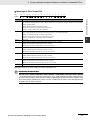
Manual Structure
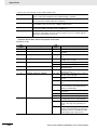
Special Information
Special information in this manual is classified as follows:
Precautions for Safe Use
Precautions on what to do and what not to do to ensure safe usage of the product.
Precautions for Correct Use
Precautions on what to do and what not to do to ensure proper operation and performance.
Additional Information
Additional information to read as required.
This information is provided to increase understanding or make operation easier.
Version Information
Information on differences in specifications and functionality for CPU Units with different unit versions
and for different versions of the Sysmac Studio is given.
Note References are provided to more detailed or related information.
Precaution on Terminology
In this manual, “download” refers to transferring data from the Sysmac Studio to the physical Controller
and “upload” refers to transferring data from the physical Controller to the Sysmac Studio.
For the Sysmac Studio, synchronization is used to both upload and download data. Here, “synchronize”
means to automatically compare the data for the Sysmac Studio on the computer with the data in the
physical Controller and transfer the data in the direction that is specified by the user.
4
NJ-series CPU Unit Built-in EtherNet/IP Port User’s Manual (W506)
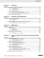
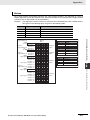
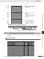
Sections in this Manual
Sections in this Manual
1
2
Introduction
Installing Ethernet
Networks
10
11
1
10
2
11
3
12
4
13
FTP Server
FTP Client
3
System-defined Variables
Related to the Built-in
EtherNet/IP Port
12
Automatic Clock
Adjustment
5
14
4
Determining
IP Addresses
13
SNMP Agent
6
15
5
Sysmac Studio Settings
for the Built-in
EtherNet/IP Port
14
Communications Performance and Communications Load
7
A
8
I
6
Testing Communications
15
Troubleshooting
9
7
Tag Data Link Functions
8
Message
Communications
9
Socket Service
A
I
Appendices
Index
NJ-series CPU Unit Built-in EtherNet/IP Port User’s Manual (W506)
5
Sections in this Manual
6
NJ-series CPU Unit Built-in EtherNet/IP Port User’s Manual (W506)
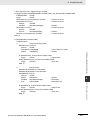
CONTENTS
CONTENTS
Introduction............................................................................................................... 1
Relevant Manuals...................................................................................................... 2
Manual Structure ...................................................................................................... 3
Sections in this Manual............................................................................................ 5
Terms and Conditions Agreement ........................................................................ 13
Safety Precautions ................................................................................................. 15
Precautions for Safe Use ....................................................................................... 16
Precautions for Correct Use .................................................................................. 17
Regulations and Standards ................................................................................... 18
Unit Versions........................................................................................................... 20
Related Manuals ..................................................................................................... 23
Revision History ..................................................................................................... 25
Section 1
1-1
Introduction
Introduction.............................................................................................................................. 1-2
1-1-1
1-1-2
1-2
System Configuration and Configuration Devices............................................................... 1-5
1-2-1
1-2-2
1-3
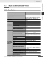
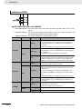
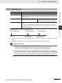
Specifications.............................................................................................................................. 1-7
Part Names and Functions ......................................................................................................... 1-9
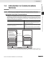
Introduction to Communications Services ......................................................................... 1-11
1-4-1
1-4-2
1-4-3
1-4-4
1-4-5
1-4-6
1-4-7
1-4-8
1-5
Devices Required to Construct a Network.................................................................................. 1-5
Support Software Required to Construct a Network................................................................... 1-6
Built-in EtherNet/IP Port.......................................................................................................... 1-7
1-3-1
1-3-2
1-4
EtherNet/IP Features .................................................................................................................. 1-2
Features of Built-in EtherNet/IP Port on NJ-series CPU Units ................................................... 1-3
CIP (Common Industrial Protocol) Communications Services ................................................. 1-11
BOOTP Client ........................................................................................................................... 1-12
FTP Server ............................................................................................................................... 1-13
FTP Client................................................................................................................................. 1-14
Automatic Clock Adjustment ..................................................................................................... 1-14
Socket Service.......................................................................................................................... 1-15
Specifying Host Names ............................................................................................................ 1-15
SNMP Agent ............................................................................................................................. 1-16
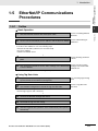
EtherNet/IP Communications Procedures .......................................................................... 1-17
1-5-1
Outline ...................................................................................................................................... 1-17
NJ-series CPU Unit Built-in EtherNet/IP Port User’s Manual (W506)
7
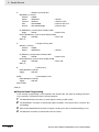
CONTENTS
Section 2
2-1
Installing Ethernet Networks
Selecting the Network Devices............................................................................................... 2-2
2-1-1
2-1-2
2-1-3
2-1-4
2-1-5
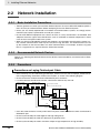
2-2
Network Installation................................................................................................................. 2-6
2-2-1
2-2-2
2-2-3
2-3
Basic Installation Precautions ..................................................................................................... 2-6
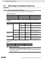
Recommended Network Devices................................................................................................ 2-6
Precautions ................................................................................................................................. 2-6
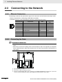
Connecting to the Network ..................................................................................................... 2-8
2-3-1
2-3-2
Section 3
Ethernet Connectors ................................................................................................................... 2-8
Connecting the Cable.................................................................................................................. 2-8
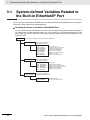
System-defined Variables Related to the Built-in
EtherNet/IP Port
3-1
System-defined Variables Related to the Built-in EtherNet/IP Port .................................... 3-2
3-2
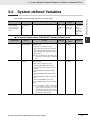
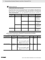
System-defined Variables ....................................................................................................... 3-3
3-3
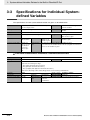
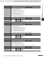
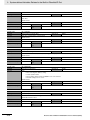
Specifications for Individual System-defined Variables .................................................... 3-12
Section 4
4-1
Determining IP Addresses
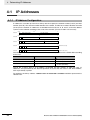
IP Addresses ............................................................................................................................ 4-2
4-1-1
4-1-2
4-1-3
4-1-4
4-2
4-3
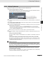
Determining IP Addresses .......................................................................................................... 4-4
Setting IP Addresses................................................................................................................... 4-5
Online Connection....................................................................................................................... 4-7
Checking the Current IP Address................................................................................................ 4-9
Private and Global Addresses.............................................................................................. 4-10
4-3-1
4-3-2
4-3-3
Section 5
IP Address Configuration ............................................................................................................ 4-2
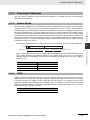
Allocating IP Addresses .............................................................................................................. 4-3
Subnet Masks ............................................................................................................................. 4-3
CIDR ........................................................................................................................................... 4-3
Built-in EtherNet/IP Port IP Address Settings....................................................................... 4-4
4-2-1
4-2-2
4-2-3
4-2-4
8
Recommended Network Devices................................................................................................ 2-2
Network Devices Manufactured by OMRON ............................................................................... 2-3
Ethernet Switch Types ................................................................................................................ 2-3
Ethernet Switch Functions .......................................................................................................... 2-3
Precautions for Ethernet Switch Selection .................................................................................. 2-4
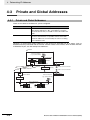
Private and Global Addresses................................................................................................... 4-10
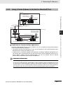
Using a Private Address for the Built-in EtherNet/IP Port ......................................................... 4-11
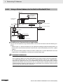
Using a Global Address for the Built-in EtherNet/IP Port .......................................................... 4-12
Sysmac Studio Settings for the Built-in EtherNet/IP Port
5-1
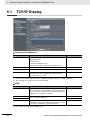
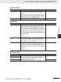
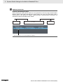
TCP/IP Display ......................................................................................................................... 5-2
5-2
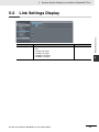
Link Settings Display .............................................................................................................. 5-5
5-3
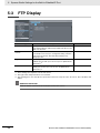
FTP Display .............................................................................................................................. 5-6
5-4
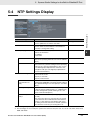
NTP Settings Display............................................................................................................... 5-7
5-5
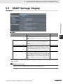
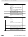
SNMP Settings Display ........................................................................................................... 5-9
5-6
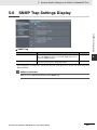
SNMP Trap Settings Display ................................................................................................. 5-11
NJ-series CPU Unit Built-in EtherNet/IP Port User’s Manual (W506)
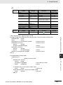
CONTENTS
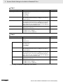
Section 6
6-1
Testing Communications
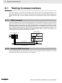
Testing Communications ........................................................................................................ 6-2
6-1-1
6-1-2
6-1-3
Section 7
7-1
Tag Data Link Functions
Introduction to Tag Data Links ............................................................................................... 7-2
7-1-1
7-1-2
7-1-3
7-1-4
7-1-5
7-1-6
7-1-7
7-2
Message Communications
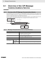
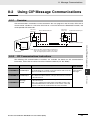
Overview of the CIP Message Communications Service..................................................... 8-2
8-1-1
8-1-2
8-2
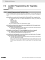
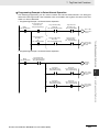
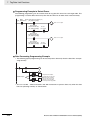
Ladder Programming for Tag Data Links .................................................................................. 7-70
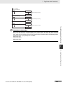
Status Flags Related to Tag Data Links.................................................................................... 7-74
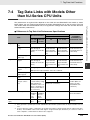
Tag Data Links with Models Other than NJ-Series CPU Units .......................................... 7-75
Section 8
8-1
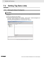
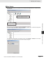
Starting the Network Configurator ............................................................................................ 7-16
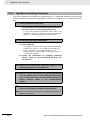
Tag Data Link Setting Procedure .............................................................................................. 7-18
Registering Devices.................................................................................................................. 7-19
Creating Tags and Tag Sets...................................................................................................... 7-21
Connection Settings.................................................................................................................. 7-32
Creating Connections Using the Wizard................................................................................... 7-41
Creating Connections by Device Dragging and Dropping ........................................................ 7-43
Connecting the Network Configurator to the Network .............................................................. 7-46
Downloading Tag Data Link Parameters................................................................................... 7-51
Uploading Tag Data Link Parameters ....................................................................................... 7-54
Verifying the Tag Data Links ..................................................................................................... 7-57
Starting and Stopping Tag Data Links ...................................................................................... 7-60
Clearing the Device Parameters ............................................................................................... 7-62
Saving the Network Configuration File ..................................................................................... 7-63
Reading a Network Configuration File ...................................................................................... 7-65
Checking Connections.............................................................................................................. 7-66
Changing Devices..................................................................................................................... 7-68
Displaying Device Status .......................................................................................................... 7-69
Ladder Programming for Tag Data Links ............................................................................ 7-70
7-3-1
7-3-2
7-4
Tag Data Links ............................................................................................................................ 7-2
Data Link Data Areas.................................................................................................................. 7-3
Tag Data Link Functions and Specifications ............................................................................... 7-6
Overview of Operation ................................................................................................................ 7-7
Starting and Stopping Tag Data Links ...................................................................................... 7-10
Controller Status ....................................................................................................................... 7-10
Concurrency of Tag Data Link Data.......................................................................................... 7-12
Setting Tag Data Links .......................................................................................................... 7-16
7-2-1
7-2-2
7-2-3
7-2-4
7-2-5
7-2-6
7-2-7
7-2-8
7-2-9
7-2-10
7-2-11
7-2-12
7-2-13
7-2-14
7-2-15
7-2-16
7-2-17
7-2-18
7-3
PING Command ......................................................................................................................... 6-2
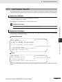
Using the PING Command ......................................................................................................... 6-2
Host Computer Operation........................................................................................................... 6-3
Overview of the CIP Message Communications Service ........................................................... 8-2
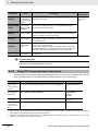
Message Communications Service Specifications ..................................................................... 8-2
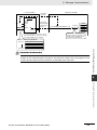
Using CIP Message Communications ................................................................................... 8-3
8-2-1
8-2-2
8-2-3
8-2-4
8-2-5
8-2-6
8-2-7
8-2-8
8-2-9
Overview..................................................................................................................................... 8-3
CIP Communications Instructions............................................................................................... 8-3
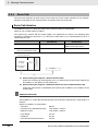
Using CIP Communications Instructions .................................................................................... 8-4
Route Path.................................................................................................................................. 8-6
Preparing Derivative Data Types to Use CIP Communications Instructions............................. 8-10
Sample Programming for CIP Connectionless (UCMM) Message Communications ............... 8-13
Sample Programming for CIP Connection (Class 3) Message Communications ..................... 8-19
Operation Timing ...................................................................................................................... 8-26
Response Codes ...................................................................................................................... 8-27
NJ-series CPU Unit Built-in EtherNet/IP Port User’s Manual (W506)
9
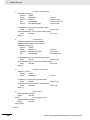
CONTENTS
8-3
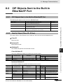
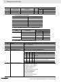
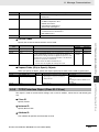
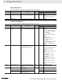
CIP Objects Sent to the Built-in EtherNet/IP Port ............................................................... 8-31
8-3-1
8-3-2
8-3-3
8-3-4
8-3-5
Section 9
9-1
Socket Service
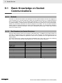
Basic Knowledge on Socket Communications..................................................................... 9-2
9-1-1
9-1-2
9-2
9-6
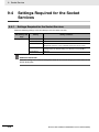
Settings Required for the Socket Services................................................................................ 9-10
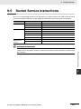
Socket Service Instructions.................................................................................................. 9-11
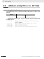
Details on Using the Socket Services.................................................................................. 9-12
9-6-1
9-6-2
9-6-3
9-6-4
9-6-5
9-7
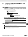
Overview ..................................................................................................................................... 9-9
Procedure.................................................................................................................................... 9-9
Settings Required for the Socket Services ......................................................................... 9-10
9-4-1
9-5
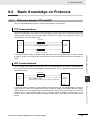
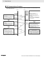
Differences between TCP and UDP............................................................................................ 9-3
Fragmenting of Send Data .......................................................................................................... 9-5
Data Reception Processing......................................................................................................... 9-6
Broadcasting ............................................................................................................................... 9-8
Overview of Built-in EtherNet/IP Port Socket Services........................................................ 9-9
9-3-1
9-3-2
9-4
Sockets ....................................................................................................................................... 9-2
Port Numbers for Socket Services .............................................................................................. 9-2
Basic Knowledge on Protocols .............................................................................................. 9-3
9-2-1
9-2-2
9-2-3
9-2-4
9-3
CIP Objects Sent to the Built-in EtherNet/IP Port ..................................................................... 8-31
Identity Object (Class ID: 01 Hex)............................................................................................. 8-31
TCP/IP Interface Object (Class ID: F5 hex) .............................................................................. 8-33
Ethernet Link Object (Class ID: F6 Hex) ................................................................................... 8-35
Controller Object (Class ID: C4 Hex) ........................................................................................ 8-39
Using the Socket Services ........................................................................................................ 9-12
Procedure to Use Socket Services ........................................................................................... 9-13
Timing Chart for Output Variables Used in Communications.................................................... 9-14
UDP Sample Programming....................................................................................................... 9-16
TCP Sample Programming ....................................................................................................... 9-21
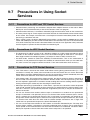
Precautions in Using Socket Services ................................................................................ 9-27
9-7-1
9-7-2
9-7-3
Section 10
Precautions for UDP and TCP Socket Services ....................................................................... 9-27
Precautions for UDP Socket Services....................................................................................... 9-27
Precautions for TCP Socket Services ....................................................................................... 9-27
FTP Server
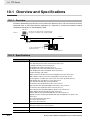
10-1 Overview and Specifications ................................................................................................ 10-2
10-1-1
10-1-2
Overview ................................................................................................................................... 10-2
Specifications ............................................................................................................................ 10-2
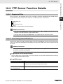
10-2 FTP Server Function Details................................................................................................. 10-3
10-2-1
10-2-2
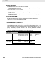
Supported Files......................................................................................................................... 10-3
Connecting to the FTP Server .................................................................................................. 10-3
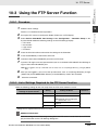
10-3 Using the FTP Server Function ............................................................................................ 10-5
10-3-1
10-3-2
Procedure.................................................................................................................................. 10-5
List of Settings Required for the FTP Server Function.............................................................. 10-5
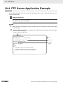
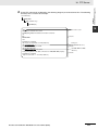
10-4 FTP Server Application Example ......................................................................................... 10-6
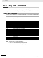
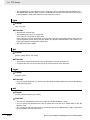
10-5 Using FTP Commands .......................................................................................................... 10-8
10-5-1
10-5-2
Table of Commands .................................................................................................................. 10-8
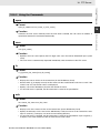
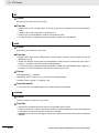
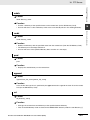
Using the Commands................................................................................................................ 10-9
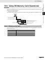
10-6 Using SD Memory Card Operations................................................................................... 10-15
10-6-1
10-6-2
10-6-3
10-6-4
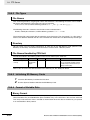
SD Memory Card Types.......................................................................................................... 10-15
File Types ................................................................................................................................ 10-16
Initializing SD Memory Cards.................................................................................................. 10-16
Format of Variable Data .......................................................................................................... 10-16
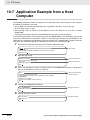
10-7 Application Example from a Host Computer .................................................................... 10-18
10
NJ-series CPU Unit Built-in EtherNet/IP Port User’s Manual (W506)
CONTENTS
Section 11
FTP Client
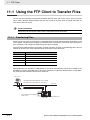
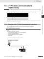
11-1 Using the FTP Client to Transfer Files................................................................................. 11-2
11-1-1
11-1-2
11-1-3
11-1-4
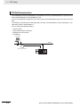
Transferring Files ...................................................................................................................... 11-2
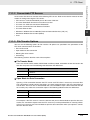
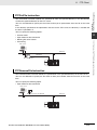
Connectable FTP Servers ........................................................................................................ 11-3
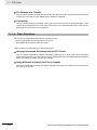
File Transfer Options................................................................................................................. 11-3
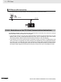
Other Functions ........................................................................................................................ 11-4
11-2 FTP Client Communications Instructions ........................................................................... 11-5
11-2-1
11-2-2
Functions of the FTP Client Communications Instructions ....................................................... 11-5
Restrictions on the FTP Client Communications Instructions................................................... 11-8
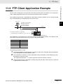
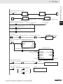
11-3 FTP Client Application Example .......................................................................................... 11-9
Section 12
Automatic Clock Adjustment
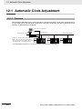
12-1 Automatic Clock Adjustment................................................................................................ 12-2
12-1-1
12-1-2
Overview................................................................................................................................... 12-2
Specifications............................................................................................................................ 12-3
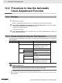
12-2 Procedure to Use the Automatic Clock Adjustment Function .......................................... 12-4
12-2-1
12-2-2
Section 13
Procedure ................................................................................................................................. 12-4
Settings Required for Automatic Clock Adjustment .................................................................. 12-4
SNMP Agent
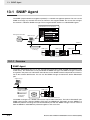
13-1 SNMP Agent ........................................................................................................................... 13-2
13-1-1
13-1-2
13-1-3
13-1-4
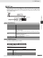
Overview................................................................................................................................... 13-2
Specifications............................................................................................................................ 13-3
SNMP Messages ...................................................................................................................... 13-3
MIB Specifications .................................................................................................................... 13-4
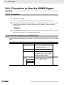
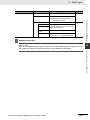
13-2 Procedure to Use the SNMP Agent .................................................................................... 13-20
13-2-1
13-2-2
Section 14
Procedures ............................................................................................................................. 13-20
Settings Required for the SNMP Agent .................................................................................. 13-20
Communications Performance and Communications
Load
14-1 Communications System...................................................................................................... 14-2
14-1-1
14-1-2
14-1-3
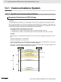
Tag Data Link Communications Method ................................................................................... 14-2
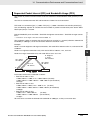
Calculating the Number of Connections ................................................................................... 14-4
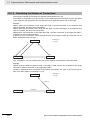
Packet Interval (RPI) Accuracy ................................................................................................. 14-5
14-2 Adjusting the Communications Load .................................................................................. 14-6
14-2-1
14-2-2
14-2-3
14-2-4
14-2-5
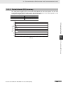
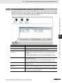
Checking Bandwidth Usage for Tag Data Links........................................................................ 14-7
Tag Data Link Bandwidth Usage and RPI................................................................................. 14-8
Adjusting Device Bandwidth Usage.......................................................................................... 14-9
Changing the RPI ................................................................................................................... 14-10
RPI Setting Examples............................................................................................................. 14-16
14-3 I/O Response Time in Tag Data Links................................................................................ 14-21
14-3-1
14-3-2
14-3-3
14-3-4
Timing of Data Transmissions................................................................................................. 14-21
Built-in EtherNet/IP Port Data Processing Time ..................................................................... 14-21
Relationship between Task Periods and Packet Intervals (RPIs) ........................................... 14-23
Maximum Tag Data Link I/O Response Time ......................................................................... 14-25
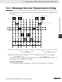
14-4 Message Service Transmission Delay ............................................................................... 14-27
NJ-series CPU Unit Built-in EtherNet/IP Port User’s Manual (W506)
11
CONTENTS
Section 15
Troubleshooting
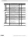
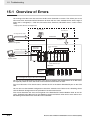
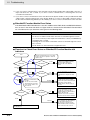
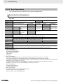
15-1 Overview of Errors................................................................................................................. 15-2
15-1-1
15-1-2
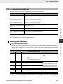
How to Check for Errors ............................................................................................................ 15-3
Errors Related to the EtherNet/IP Function Module.................................................................. 15-6
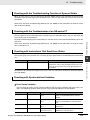
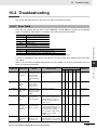
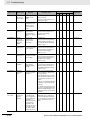
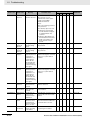
15-2 Troubleshooting..................................................................................................................... 15-9
15-2-1
15-2-2
15-2-3
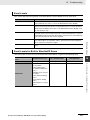
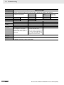
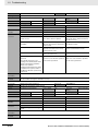
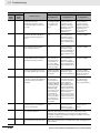
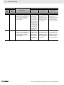
Error Table................................................................................................................................. 15-9
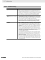
Error Descriptions ................................................................................................................... 15-14
Troubleshooting....................................................................................................................... 15-38
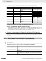
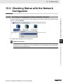
15-3 Checking Status with the Network Configurator .............................................................. 15-39
15-3-1
15-3-2
The Network Configurator’s Device Monitor Function............................................................. 15-39
Connection Status Codes and Troubleshooting ...................................................................... 15-46
Appendices
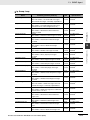
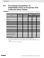
A-1 Functional Comparison of EtherNet/IP Ports on NJ-series CPU Units
and Other Series....................................................................................................................A-2
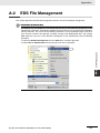
A-2 EDS File Management .............................................................................................................A-3
A-2-1
A-2-2
A-2-3
A-2-4
A-2-5
A-2-6
A-2-7
Installing EDS Files .....................................................................................................................A-4
Creating EDS Files......................................................................................................................A-4
Deleting EDS Files ......................................................................................................................A-4
Saving EDS Files ........................................................................................................................A-5
Searching EDS Files ...................................................................................................................A-5
Displaying EDS File Properties...................................................................................................A-6
Creating EDS Index Files............................................................................................................A-6
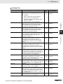
A-3 Precautions for Using the Network Configurator on Windows XP, Windows Vista,
or Windows 7 .........................................................................................................................A-7
A-3-1
Changing Windows Firewall Settings ..........................................................................................A-7
A-4 Variable Memory Allocation Methods ..................................................................................A-10
A-4-1
A-4-2
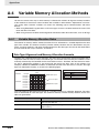
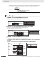
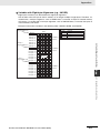
Variable Memory Allocation Rules ............................................................................................A-10
Important Case Examples.........................................................................................................A-18
A-5 Precautions When Accessing External Outputs from NJ-series CPU Units....................A-22
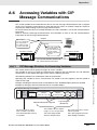
A-6 Accessing Variables with CIP Message Communications ................................................A-23
A-6-1
A-6-2
A-6-3
A-6-4
A-6-5
CIP Message Structure for Accessing Variables.......................................................................A-23
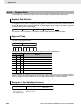
Request Path ............................................................................................................................A-24
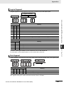
Read and Write Services for Variables .....................................................................................A-26
Specifying Variable Names in Request Paths ...........................................................................A-29
Specifying Data Formats When Writing to Variables ................................................................A-31
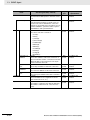
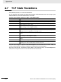
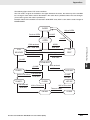
A-7 TCP State Transitions............................................................................................................A-36
A-8 Version Information ...............................................................................................................A-38
Index
12
NJ-series CPU Unit Built-in EtherNet/IP Port User’s Manual (W506)
Terms and Conditions Agreement
Terms and Conditions Agreement
Warranty, Limitations of Liability
Warranties
Exclusive Warranty
Omron’s exclusive warranty is that the Products will be free from defects in materials and workmanship for a period of twelve months from the date of sale by Omron (or such other period expressed in
writing by Omron). Omron disclaims all other warranties, express or implied.
Limitations
OMRON MAKES NO WARRANTY OR REPRESENTATION, EXPRESS OR IMPLIED, ABOUT
NON-INFRINGEMENT, MERCHANTABILITY OR FITNESS FOR A PARTICULAR PURPOSE OF
THE PRODUCTS. BUYER ACKNOWLEDGES THAT IT ALONE HAS DETERMINED THAT THE
PRODUCTS WILL SUITABLY MEET THE REQUIREMENTS OF THEIR INTENDED USE.
Omron further disclaims all warranties and responsibility of any type for claims or expenses based
on infringement by the Products or otherwise of any intellectual property right.
Buyer Remedy
Omron’s sole obligation hereunder shall be, at Omron’s election, to (i) replace (in the form originally
shipped with Buyer responsible for labor charges for removal or replacement thereof) the non-complying Product, (ii) repair the non-complying Product, or (iii) repay or credit Buyer an amount equal
to the purchase price of the non-complying Product; provided that in no event shall Omron be
responsible for warranty, repair, indemnity or any other claims or expenses regarding the Products
unless Omron’s analysis confirms that the Products were properly handled, stored, installed and
maintained and not subject to contamination, abuse, misuse or inappropriate modification. Return of
any Products by Buyer must be approved in writing by Omron before shipment. Omron Companies
shall not be liable for the suitability or unsuitability or the results from the use of Products in combination with any electrical or electronic components, circuits, system assemblies or any other materials or substances or environments. Any advice, recommendations or information given orally or in
writing, are not to be construed as an amendment or addition to the above warranty.
See http://www.omron.com/global/ or contact your Omron representative for published information.
Limitation on Liability; Etc
OMRON COMPANIES SHALL NOT BE LIABLE FOR SPECIAL, INDIRECT, INCIDENTAL, OR CONSEQUENTIAL DAMAGES, LOSS OF PROFITS OR PRODUCTION OR COMMERCIAL LOSS IN ANY
WAY CONNECTED WITH THE PRODUCTS, WHETHER SUCH CLAIM IS BASED IN CONTRACT,
WARRANTY, NEGLIGENCE OR STRICT LIABILITY.
Further, in no event shall liability of Omron Companies exceed the individual price of the Product on
which liability is asserted.
NJ-series CPU Unit Built-in EtherNet/IP Port User’s Manual (W506)
13
Terms and Conditions Agreement
Application Considerations
Suitability of Use
Omron Companies shall not be responsible for conformity with any standards, codes or regulations
which apply to the combination of the Product in the Buyer’s application or use of the Product. At
Buyer’s request, Omron will provide applicable third party certification documents identifying ratings
and limitations of use which apply to the Product. This information by itself is not sufficient for a complete determination of the suitability of the Product in combination with the end product, machine, system, or other application or use. Buyer shall be solely responsible for determining appropriateness of
the particular Product with respect to Buyer’s application, product or system. Buyer shall take application responsibility in all cases.
NEVER USE THE PRODUCT FOR AN APPLICATION INVOLVING SERIOUS RISK TO LIFE OR
PROPERTY WITHOUT ENSURING THAT THE SYSTEM AS A WHOLE HAS BEEN DESIGNED TO
ADDRESS THE RISKS, AND THAT THE OMRON PRODUCT(S) IS PROPERLY RATED AND
INSTALLED FOR THE INTENDED USE WITHIN THE OVERALL EQUIPMENT OR SYSTEM.
Programmable Products
Omron Companies shall not be responsible for the user’s programming of a programmable Product, or
any consequence thereof.
Disclaimers
Performance Data
Data presented in Omron Company websites, catalogs and other materials is provided as a guide for
the user in determining suitability and does not constitute a warranty. It may represent the result of
Omron’s test conditions, and the user must correlate it to actual application requirements. Actual performance is subject to the Omron’s Warranty and Limitations of Liability.
Change in Specifications
Product specifications and accessories may be changed at any time based on improvements and other
reasons. It is our practice to change part numbers when published ratings or features are changed, or
when significant construction changes are made. However, some specifications of the Product may be
changed without any notice. When in doubt, special part numbers may be assigned to fix or establish
key specifications for your application. Please consult with your Omron’s representative at any time to
confirm actual specifications of purchased Product.
Errors and Omissions
Information presented by Omron Companies has been checked and is believed to be accurate; however, no responsibility is assumed for clerical, typographical or proofreading errors or omissions.
14
NJ-series CPU Unit Built-in EtherNet/IP Port User’s Manual (W506)
Safety Precautions
Safety Precautions
Refer to the following manuals for safety precautions.
• NJ-series CPU Unit Hardware User's Manual (Cat. No. W500)
• NJ-series CPU Unit Software User's Manual (Cat. No. W501)
NJ-series CPU Unit Built-in EtherNet/IP Port User’s Manual (W506)
15
Precautions for Safe Use
Precautions for Safe Use
Refer to the following manuals for precautions for safe use.
• NJ-series CPU Unit Hardware User's Manual (Cat. No. W500)
• NJ-series CPU Unit Software User's Manual (Cat. No. W501)
16
NJ-series CPU Unit Built-in EtherNet/IP Port User’s Manual (W506)
Precautions for Correct Use
Precautions for Correct Use
Refer to the following manuals for precautions for correct use.
• NJ-series CPU Unit Hardware User's Manual (Cat. No. W500)
• NJ-series CPU Unit Software User's Manual (Cat. No. W501)
NJ-series CPU Unit Built-in EtherNet/IP Port User’s Manual (W506)
17
Regulations and Standards
Regulations and Standards
Conformance to EC Directives
Applicable Directives
• EMC Directives
• Low Voltage Directive
Concepts
EMC Directive
OMRON devices that comply with EC Directives also conform to the related EMC standards so that
they can be more easily built into other devices or the overall machine. The actual products have
been checked for conformity to EMC standards.*
Whether the products conform to the standards in the system used by the customer, however, must
be checked by the customer. EMC-related performance of the OMRON devices that comply with EC
Directives will vary depending on the configuration, wiring, and other conditions of the equipment or
control panel on which the OMRON devices are installed. The customer must, therefore, perform the
final check to confirm that devices and the overall machine conform to EMC standards.
* Applicable EMC (Electromagnetic Compatibility) standards are as follows:
EMS (Electromagnetic Susceptibility): EN 61131-2 and EN 61000-6-2
EMI (Electromagnetic Interference): EN 61131-2 and EN 61000-6-4 (Radiated emission: 10-m regulations)
Low Voltage Directive
Always ensure that devices operating at voltages of 50 to 1,000 VAC and 75 to 1,500 VDC meet the
required safety standards. The applicable directive is EN 61131-2.
Conformance to EC Directives
The NJ-series Controllers comply with EC Directives. To ensure that the machine or device in which
the NJ-series Controller is used complies with EC Directives, the Controller must be installed as follows:
• The NJ-series Controller must be installed within a control panel.
• You must use reinforced insulation or double insulation for the DC power supplies connected to
DC Power Supply Units and I/O Units.
• NJ-series Controllers that comply with EC Directives also conform to the Common Emission Standard (EN 61000-6-4). Radiated emission characteristics (10-m regulations) may vary depending
on the configuration of the control panel used, other devices connected to the control panel, wiring, and other conditions.
You must therefore confirm that the overall machine or equipment complies with EC Directives.
18
NJ-series CPU Unit Built-in EtherNet/IP Port User’s Manual (W506)
Regulations and Standards
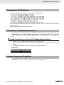
Conformance to KC Standards
Observe the following precaution if you use NX-series Units in Korea.
Class A Device (Broadcasting Communications Device for Office Use)
This device obtained EMC registration for office use (Class A), and it is intended to be used in places
other than homes.
Sellers and/or users need to take note of this.
Conformance to Shipbuilding Standards
The NJ-series Controllers comply with the following shipbuilding standards. Applicability to the shipbuilding standards is based on certain usage conditions. It may not be possible to use the product in
some locations. Contact your OMRON representative before attempting to use a Controller on a
ship.
Usage Conditions for NK and LR Shipbuilding Standards
• The NJ-series Controller must be installed within a control panel.
• Gaps in the door to the control panel must be completely filled or covered with gaskets or other
material.
• The following noise filter must be connected to the power supply line.
Noise Filter
Manufacturer
Cosel Co., Ltd.
Model
TAH-06-683
Software Licenses and Copyrights
This product incorporates certain third party software. The license and copyright information associated with this software is available at http://www.fa.omron.co.jp/nj_info_e/.
NJ-series CPU Unit Built-in EtherNet/IP Port User’s Manual (W506)
19
Unit Versions
Unit Versions
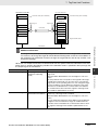
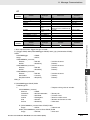
Unit Versions
A “unit version” has been introduced to manage CPU Units in the NJ Series according to differences in
functionality accompanying Unit upgrades.
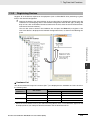
Notation of Unit Versions on Products
The unit version is given on the ID information label of the products for which unit versions are managed, as shown below.
Example for NJ-series NJ501-@@@@ CPU Unit:
ID information label
Unit version
Unit model
NJ501 - 1500
Ver.1.@@
PORT1 MAC ADDRESS: @@@@@@@@@@@@
PORT2 MAC ADDRESS: @@@@@@@@@@@@
Lot No. DDMYY@
xxxx
Lot number and serial number
MAC address
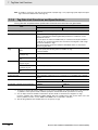
The following information is provided on the ID information label.
Item
Description
Unit model
Gives the model of the Unit.
Unit version
Gives the unit version of the Unit.
Lot number and
serial number
Gives the lot number and serial number of the Unit.
DDMYY: Lot number, @: For use by OMRON, xxxx: Serial number
“M” gives the month (1 to 9: January to September, X: October, Y: November, Z: December)
MAC address
Gives the MAC address of the built-in port on the Unit.
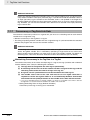
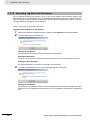
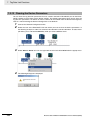
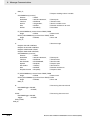
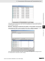
Confirming Unit Versions with Sysmac Studio
You can use the Unit Production Information on the Sysmac Studio to check the unit version of the CPU
Unit, CJ-series Special I/O Units, CJ-series CPU Bus Units, and EtherCAT slaves. The unit versions of
CJ-series Basic I/O Units cannot be checked from the Sysmac Studio.
CPU Unit and CJ-series Units
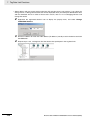
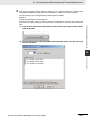
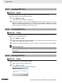
1
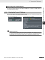
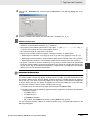
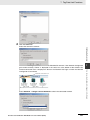
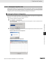
Double-click CPU/Expansion Racks under Configurations and Setup in the Multiview
Explorer. Or, right-click CPU/Expansion Racks under Configurations and Setup and select
Edit from the menu.
The Unit Editor is displayed for the Controller Configurations and Setup layer.
20
NJ-series CPU Unit Built-in EtherNet/IP Port User’s Manual (W506)
Unit Versions
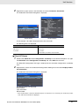
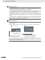
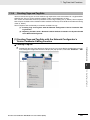
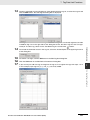
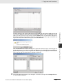
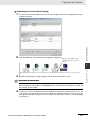
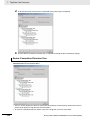
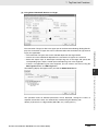
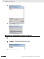
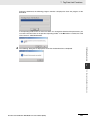
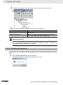
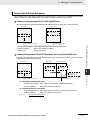
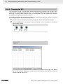
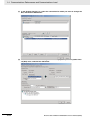
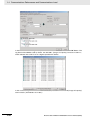
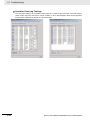
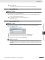
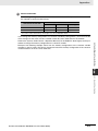
2
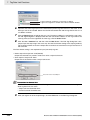
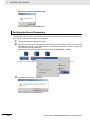
Right-click any open space in the Unit Editor and select Production Information.
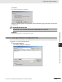
The Production Information Dialog Box is displayed.
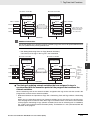
Simple Display
Detailed Display
In this example, “Ver.1.00” is displayed next to the unit model.
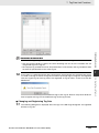
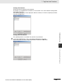
The following items are displayed.
CPU Unit
CJ-series Units
Unit model
Unit model
Unit version
Unit version
Lot number
Lot number
Rack number, slot number, and unit number
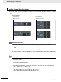
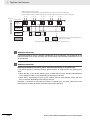
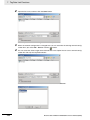
EtherCAT Slaves
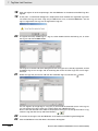
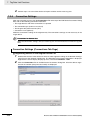
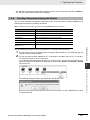
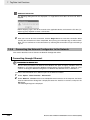
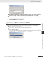
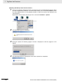
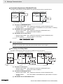
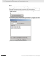
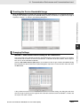
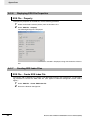
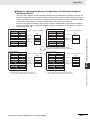
1
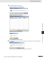
Double-click EtherCAT under Configurations and Setup in the Multiview Explorer. Or, rightclick EtherCAT under Configurations and Setup and select Edit from the menu.
The EtherCAT Configuration Tab Page is displayed for the Controller Configurations and Setup
layer.
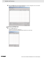
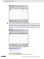
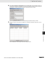
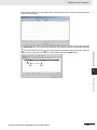
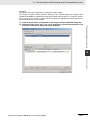
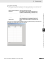
2
Right-click the master in the EtherCAT Configurations Editing Pane and select Display Production Information.
The Production Information Dialog Box is displayed.
The following items are displayed.
Node address
Type information*
Serial number
* If the model number cannot be determined (such as when there is no ESI file), the vendor ID, product
code, and revision number are displayed.
NJ-series CPU Unit Built-in EtherNet/IP Port User’s Manual (W506)
21
Unit Versions
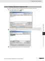
Confirming Unit Versions with System-defined Variable
You can access the _UnitVersion (Unit Version) system-defined variable from the user program to check
the unit version of the CPU Unit.
_UnitVersion is an USINT array variable with two elements. _UnitVersion[0] and _UnitVersion[1] correspond to the integer part and the fractional part of the unit version, respectively.
Version Information
A CPU Unit with unit version 1.08 or later and the Sysmac Studio version 1.09 or higher are
required to confirm the unit version using the system-defined variable.
Additional Information
Refer to the manual for the specific Unit for the unit versions of the CPU Units, Communications
Coupler Units, NX Units, and Safety Control Units to which the database connection service and
other functions were added.
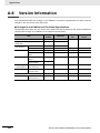
Unit Versions and Sysmac Studio Versions
The functions that are supported depend on the unit version of the NJ-series CPU Unit. The version of
Sysmac Studio that supports the functions that were added for an upgrade is also required to use those
functions. Refer to A-8 Version Information for the relationship between the unit versions of the CPU
Units and the Sysmac Studio versions, and for the functions that are supported by each unit version.
Unit Version Notation
In this manual, unit versions are specified as shown in the following table.
Product nameplate
Notation in this manual
“Ver.1.0” or later to the right of
the lot number
Unit version 1.0 or later
Remarks
Unless unit versions are specified, the information in this manual
applies to all unit versions.
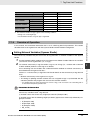
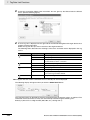
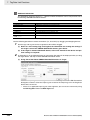
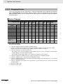
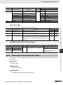
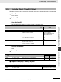
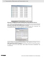
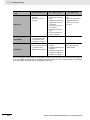
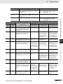
Unit Versions of CPU Units and Support Software Versions
When you set tag data links for the built-in EtherNet/IP port on an NJ-series CPU Unit, use the version
of the Network Configurator that is given in the following table.
Unit version of CPU
Unit
22
Network Configurator for EtherNet/IP
Version 3.40 or lower
Version 3.40
Version 3.50
Version 3.53 or higher
1.00
NA
OK
OK
OK
1.01 or 1.02
NA
NA
OK
OK
1.03 or later
NA
NA
NA
OK
NJ-series CPU Unit Built-in EtherNet/IP Port User’s Manual (W506)
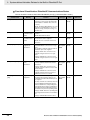
Related Manuals
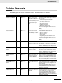
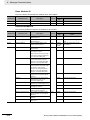
Related Manuals
The followings are the manuals related to this manual. Use these manuals for reference.
Manual name
NJ-series CPU Unit
Hardware User’s Manual
Cat. No.
W500
Model numbers
NJ501-@@@@
NJ301-@@@@
Application
Description
Learning the basic specifications of the NJ-series
CPU Units, including introductory information,
designing, installation, and
maintenance. Mainly hardware information is provided.
An introduction to the entire NJ-series system is
provided along with the following information on
the CPU Unit.
• Features and system configuration
• Introduction
• Part names and functions
• General specifications
• Installation and wiring
• Maintenance and inspection
Use this manual together with the NJ-series
CPU Unit Software User’s Manual (Cat. No.
W501).
NJ-series CPU Unit Software User’s Manual
W501
NJ501-@@@@
NJ301-@@@@
Learning how to program
and set up an NJ-series
CPU Unit. Mainly software
information is provided.
The following information is provided on a Controller built with an NJ501 CPU Unit.
• CPU Unit operation
• CPU Unit features
• Initial settings
• Programming based on IEC 61131-3 language specifications
Use this manual together with the NJ-series
CPU Unit Hardware User’s Manual (Cat. No.
W500).
NJ-series Instructions
Reference Manual
W502
NJ501-@@@@
NJ301-@@@@
Learning detailed specifications on the basic
instructions of an NJ-series
CPU Unit.
The instructions in the instruction set (IEC
61131-3 specifications) are described. When
programming, use this manual together with the
NJ-series CPU Unit Hardware User’s Manual
(Cat. No. W500) and NJ-series CPU Unit Software User’s Manual (Cat. No. W501).
NJ-series CPU Unit
Motion Control User’s
Manual
W507
NJ501-@@@@
NJ301-@@@@
Learning about motion
control settings and programming concepts.
The settings and operation of the CPU Unit and
programming concepts for motion control are
described. Use this manual together with the
NJ-series CPU Unit Hardware User’s Manual
(Cat. No. W500) and NJ-series CPU Unit Software User’s Manual (Cat. No. W501).
NJ-series Motion Control
Instructions Reference
Manual
W508
NJ501-@@@@
NJ301-@@@@
Learning about the specifications of the motion control instructions that are
provided by OMRON.
NJ-series CPU Unit Builtin EtherCAT® Port User’s
Manual
W505
NJ501-@@@@
NJ301-@@@@
Using the built-in EtherCAT
port on an NJ-series CPU
Unit.
The motion control instructions are described.
When programming, use this manual together
with the NJ-series CPU Unit Hardware User’s
Manual (Cat. No. W500), NJ-series CPU Unit
Software User’s Manual (Cat. No. W501) and
NJ-series CPU Unit Motion Control User’s Manual (Cat. No. W507).
Information on the built-in EtherCAT port is provided. This manual provides an introduction and
provides information on the configuration, features, and setup.
Use this manual together with the NJ-series
CPU Unit Hardware User’s Manual (Cat. No.
W500) and NJ-series CPU Unit Software User’s
Manual (Cat. No. W501).
NJ-series CPU Unit Built-
W506
NJ501-@@@@
NJ301-@@@@
Using the built-in EtherNet/IP port on an NJ-series
CPU Unit.
in EtherNet/IPTM Port
User’s Manual
NJ-series CPU Unit Built-in EtherNet/IP Port User’s Manual (W506)
Information on the built-in EtherNet/IP port is
provided. Information is provided on the basic
setup, tag data links, and other features.
Use this manual together with the NJ-series
CPU Unit Hardware User’s Manual (Cat. No.
W500) and NJ-series CPU Unit Software User’s
Manual (Cat. No. W501).
23
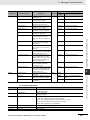
Related Manuals
Manual name
Cat. No.
Model numbers
Application
Description
NJ-series Database Connection CPU Units User’s
Manual
W527
NJ501-1@20
Using the database connection service with NJseries Controllers
Describes the database connection service.
NJ-series Troubleshooting Manual
W503
NJ501-@@@@
NJ301-@@@@
Learning about the errors
that may be detected in an
NJ-series Controller.
Concepts on managing errors that may be
detected in an NJ-series Controller and information on individual errors are described.
Use this manual together with the NJ-series
CPU Unit Hardware User’s Manual (Cat. No.
W500) and NJ-series CPU Unit Software User’s
Manual (Cat. No. W501).
Sysmac Studio Version 1
Operation Manual
W504
SYSMACSE2@@@
Learning about the operating procedures and functions of the Sysmac Studio.
Describes the operating procedures of the Sysmac Studio.
24
NJ-series CPU Unit Built-in EtherNet/IP Port User’s Manual (W506)
Revision History
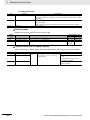
Revision History
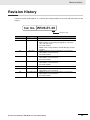
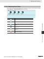
A manual revision code appears as a suffix to the catalog number on the front and back covers of the
manual.
Cat. No. W506-E1-08
Revision code
Revision code
01
02
Date
July 2011
March 2012
03
May 2012
04
August 2012
05
February 2013
06
07
April 2013
June 2013
08
December 2013
Revised content
Original production
• Added information on the NJ301-1@00.
• Made changes accompanying the upgrade to unit version
1.01 of the CPU Unit.
• Corrected mistakes.
• Added A-6 Accessing Variables with CIP Message Communications.
• Added information on functional support for unit version
1.02 and later of the CPU Units.
• Corrected mistakes.
• Added information on functional support for unit version
1.03 and later of the CPU Units.
• Corrected mistakes.
• Added information on functional support for unit version
1.04 and later of the CPU Units.
• Corrected mistakes.
• Corrected mistakes.
• Added information on functional support for unit version
1.06 and later of the CPU Units.
• Added information on functional support for unit version
1.08 and later of the CPU Units.
• Corrected mistakes.
NJ-series CPU Unit Built-in EtherNet/IP Port User’s Manual (W506)
25
Revision History
26
NJ-series CPU Unit Built-in EtherNet/IP Port User’s Manual (W506)
1
Introduction
1-1 Introduction . . . . . . . . . . . . . . . . . . . . . . . . . . . . . . . . . . . . . . . . . . . . . . . . . . 1-2
1-1-1
1-1-2
EtherNet/IP Features . . . . . . . . . . . . . . . . . . . . . . . . . . . . . . . . . . . . . . . . . . . . 1-2
Features of Built-in EtherNet/IP Port on NJ-series CPU Units . . . . . . . . . . . . 1-3
1-2 System Configuration and Configuration Devices . . . . . . . . . . . . . . . . . . . 1-5
1-2-1
1-2-2
Devices Required to Construct a Network . . . . . . . . . . . . . . . . . . . . . . . . . . . . 1-5
Support Software Required to Construct a Network . . . . . . . . . . . . . . . . . . . . 1-6
1-3 Built-in EtherNet/IP Port . . . . . . . . . . . . . . . . . . . . . . . . . . . . . . . . . . . . . . . . 1-7
1-3-1
1-3-2
Specifications . . . . . . . . . . . . . . . . . . . . . . . . . . . . . . . . . . . . . . . . . . . . . . . . . . 1-7
Part Names and Functions . . . . . . . . . . . . . . . . . . . . . . . . . . . . . . . . . . . . . . . 1-9
1-4 Introduction to Communications Services . . . . . . . . . . . . . . . . . . . . . . . . 1-11
1-4-1
1-4-2
1-4-3
1-4-4
1-4-5
1-4-6
1-4-7
1-4-8
CIP (Common Industrial Protocol) Communications Services . . . . . . . . . . .
BOOTP Client . . . . . . . . . . . . . . . . . . . . . . . . . . . . . . . . . . . . . . . . . . . . . . . .
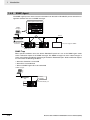
FTP Server . . . . . . . . . . . . . . . . . . . . . . . . . . . . . . . . . . . . . . . . . . . . . . . . . .
FTP Client . . . . . . . . . . . . . . . . . . . . . . . . . . . . . . . . . . . . . . . . . . . . . . . . . . .
Automatic Clock Adjustment . . . . . . . . . . . . . . . . . . . . . . . . . . . . . . . . . . . . .
Socket Service . . . . . . . . . . . . . . . . . . . . . . . . . . . . . . . . . . . . . . . . . . . . . . . .
Specifying Host Names . . . . . . . . . . . . . . . . . . . . . . . . . . . . . . . . . . . . . . . . .
SNMP Agent . . . . . . . . . . . . . . . . . . . . . . . . . . . . . . . . . . . . . . . . . . . . . . . . .
1-11
1-12
1-13
1-14
1-14
1-15
1-15
1-16
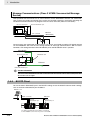
1-5 EtherNet/IP Communications Procedures . . . . . . . . . . . . . . . . . . . . . . . . . 1-17
1-5-1
Outline . . . . . . . . . . . . . . . . . . . . . . . . . . . . . . . . . . . . . . . . . . . . . . . . . . . . . . 1-17
NJ-series CPU Unit Built-in EtherNet/IP Port User’s Manual (W506)
1-1
1 Introduction
1-1
1-1-1
Introduction
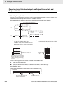
EtherNet/IP Features
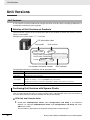
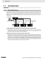
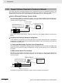
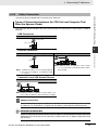
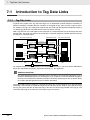
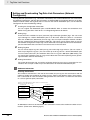
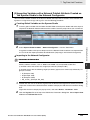
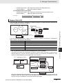
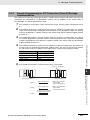
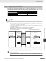
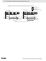
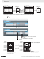
EtherNet/IP is an industrial multi-vendor network that uses Ethernet. The EtherNet/IP specifications are
open standards managed by the ODVA (Open DeviceNet Vendor Association), just like DeviceNet. EtherNet/IP is not just a network between Controllers. It is also used as a field network. Because EtherNet/IP uses standard Ethernet technology, various general-purpose Ethernet devices can be used in
the network.
Sysmac Studio
(Support Software)
Ethernet (LAN) port
(3) Ethernet switch
(2) Twisted-pair cable
100 m
max.
(1) Built-in EtherNet/IP
port on NJ-series
Controller
(1) Built-in EtherNet/IP
port on NJ-series
Controller
(1) Built-in EtherNet/IP
port on NJ-series
Controller
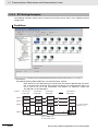
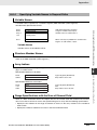
EtherNet/IP System Configuration Example
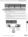
High-speed, High-capacity Data Exchange through Tag Data Links
The EtherNet/IP protocol supports implicit communications, which allows cyclic communications
(called tag data links in this manual) with EtherNet/IP devices. Data of up to 9,600 words can be
exchanged at high speed between Controllers and devices.
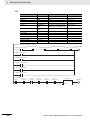
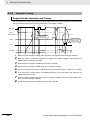
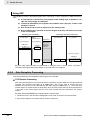
Tag Data Link (Cyclic Communications) Cycle Time
Tag data links (cyclic communications) operate at the cyclic period specified for each application,
regardless of the number of nodes. Data is exchanged over the network at the refresh cycle set for
each connection, so the communications refresh cycle will not increase even if the number of nodes
is increased, i.e., the concurrency of the connection’s data is maintained. Because the refresh cycle
can be set for each connection, each application can communicate at its ideal refresh cycle. For
example, interprocess interlocks can be transferred at high speed, while the production commands
and the status monitor information are transferred at low speed.
1-2
NJ-series CPU Unit Built-in EtherNet/IP Port User’s Manual (W506)
1 Introduction
Features of Built-in EtherNet/IP Port on NJ-series CPU Units
Tag Data Links
Cyclic communications between Controllers or between Controllers and other devices are possible
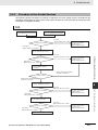
on an EtherNet/IP network. Tag data links can quickly perform data exchanges for up to 9,600 words
of data.
1
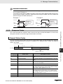
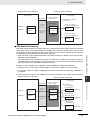
Message Communications
BOOTP Client
If the NJ-series built-in EtherNet/IP port is set in the BOOTP settings, the BOOTP client operates
when the Controller power is turned ON, and the IP address is obtained from the BOOTP server. It is
possible to set all of the IP addresses of multiple built-in EtherNet/IP ports at the same time.
Built-in FTP Server for File Transfers to and from Host Computers
An FTP server is built into the Controller. You can use it to read and write data within the Controller
as files from workstations and computers with FTP clients. The FTP server enables the transfer of
large amounts of data from a client without any additional ladder programming.
FTP Client for File Transfers to and from Host Computers
An FTP client is built into the Controller so that you can read and write files on workstations and
computers that have an FTP server from the Controller.
You can use the FTP client communications instructions to transfer one or more files between the
Controller and an FTP server.
Automatic Controller Clock Adjustment
The clocks built into Controllers connected to Ethernet can be automatically adjusted to the time of
the clock in the NTP server. If all of the clocks in the system are automatically adjusted to the same
time, time stamps can be used to analyze production histories.
* A separate NTP server is necessary to automatically adjust the Controller clocks.
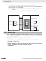
Socket Services
Socket services can be used to send/receive data between general-purpose applications and Controllers. You can use these communications services to send and receive any data to and from
remote nodes, i.e., between host computers and Controllers or between Controllers. You can execute socket communications instructions in order in a program to execute communications processes with the socket services. There are two socket services, the UDP socket service and TCP
socket service.
Host Names
You can directly specify IP addresses, but you can also use the host names instead of the IP
addresses for NTP servers, SNMP managers, or the destinations of socket instructions and CIP
communications instructions (DNS client or hosts settings). This is useful, for example, when server
IP addresses change for system revisions because the IP addresses are automatically found when
host names are used.
* A separate DNS server is necessary to use host names with the DNS client.
* The DNS server is specified directly using its IP address.
1-3
1-1-2 Features of Built-in EtherNet/IP Port on NJ-series CPU Units
You can send CIP commands to devices on the EtherNet/IP network when required by execution of
CIP communications instructions in a program. As a result, it is possible to send and receive data
with devices on the EtherNet/IP network.
NJ-series CPU Unit Built-in EtherNet/IP Port User’s Manual (W506)
1-1 Introduction
1-1-2
1 Introduction
Network Management with an SNMP Manager
The SNMP agent passes internal status information from the built-in EtherNet/IP port to network
management software that uses an SNMP manager.
* A separate SNMP manager is necessary for network management.
Complete Troubleshooting Functions
A variety of functions are provided to quickly identify and handle errors.
• Self-diagnosis at startup
• Event log that records the time of occurrence and other error details
Additional Information
CIP (Common Industrial Protocol)
CIP is a shared industrial protocol for the OSI application layer. The CIP is used in networks such
as EtherNet/IP, CompoNet, and DeviceNet. Data can be routed easily between networks that are
based on the CIP. You can therefore easily configure a transparent network from the field device
level to the host level. The CIP has the following advantages.
• Destination nodes are specified by a relative path, without fixed routing tables.
• The CIP uses the producer/consumer model. Nodes in the network are arranged on the same
level and it is possible to communicate with required devices whenever it is necessary. The
consumer node will receive data sent from a producer node when the connection ID in the
packet indicates that the node requires the data. Because the producer can send the same
data with the same characteristics in a multicast format, the time required for the transfer is
fixed and not dependent on the number of consumer nodes. (Either multicast or unicast can be
selected.)
1-4
NJ-series CPU Unit Built-in EtherNet/IP Port User’s Manual (W506)
1 Introduction
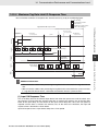
1-2-1
1-2 System Configuration and
Configuration Devices
1-2
System Configuration and
Configuration Devices
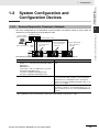
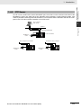
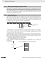
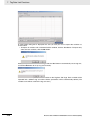
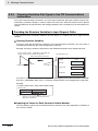
Devices Required to Construct a Network
The basic configuration for an EtherNet/IP system includes one Ethernet switch to which nodes are
attached in star configuration using twisted-pair cable.
100 m
max.
Ethernet (LAN) port
1-2-1 Devices Required to Construct a Network
(3) Ethernet switch
Sysmac Studio
(Support Software)
(2) Twisted-pair cable
(1) Built-in EtherNet/IP
port on NJ-series
CPU Unit
(1) Built-in EtherNet/IP
port on NJ-series
CPU Unit
(1) Built-in EtherNet/IP
port on NJ-series
CPU Unit
The following products are also required to build a network. Obtain them in advance.
Network device
Function
(1) Per Node
NJ501-@@@@ NJ-series CPU Unit (built-in EtherNet/IP port)
OMRON PLCs
CJ2H-CPU@@-EIP or CJ2M-CPU3@ CJ2 CPU
Unit (built-in EtherNet/IP port)
CJ-series CJ1W-EIP21 EtherNet/IP Unit*
CS-series CS1W-EIP21 EtherNet/IP Unit
These Units are used to connect to an EtherNet/IP network.
(2) Twisted-pair cable
The twisted-pair cable has a RJ45 Modular Connector
at each end. This cable is used to connect the built-in
EtherNet/IP port or EtherNet/IP Unit to an Ethernet
switch. Use an STP (shielded twisted-pair) cable of category 5, 5e, or higher.
(3) Ethernet switch
This is a relay device that connects multiple nodes in a
star LAN. For details on recommended devices to configure a network, refer to 2-1-1 Recommended Network
Devices.
* The CJ1W-EIP21 cannot be mounted to an NJ-series CPU Unit with a unit version of 1.00.
NJ-series CPU Unit Built-in EtherNet/IP Port User’s Manual (W506)
1
1-5
1 Introduction
1-2-2
Support Software Required to Construct a Network
This section describes the Support Software that is required to construct an EtherNet/IP network. The
built-in EtherNet/IP port has Ethernet Settings and Tag Data Link Settings, which are stored in the nonvolatile memory of the CPU Unit. Support Software is provided for each, as described below.
Built-in Ethernet/IP Settings: Sysmac Studio
Use the Sysmac Studio to set the basic settings, such as the local IP address and subnet mask of
the built-in EtherNet/IP port. The Sysmac Studio can also be used to check if data I/O is being performed correctly for tag data links.
Windows Computer
Sysmac Studio
Edit Parameters
Dialog Box
Built-in EtherNet/IP port
settings (non-volatile memory)
NJ-series CPU Unit
Built-in EtherNet/IP port
Refer to the Sysmac Studio Version 1 Operation Manual (Cat. No. W504) for details on the Sysmac
Studio.
Tag Data Link Settings: Network Configurator
Use the Network Configurator to set the tag data links for the built-in EtherNet/IP port. (The Network
Configurator is included in the Sysmac Studio Standard Edition.) The main functions of the Network
Configurator are given below.
1) Setting and Monitoring Tag Data Links (Connections)
The network device configuration and tag data links (connections) can be created and edited. After
connecting to the network, the device configuration and tag data link settings can be uploaded and
monitored.
2) Multi-vendor Device Connections
EDS files can be installed and deleted so that you can construct, set, and manage networks that
contain EtherNet/IP devices from other companies. The IP addresses of EtherNet/IP devices can
also be changed.
Windows computer with
Network Configurator
Tag Data Link Settings
(non-volatile memory)
Edit Device
Parameters
Dialog Box
Transferred.
NJ-series CPU Unit
Built-in EtherNet/IP port
For details on the Network Configurator, refer to Section 7 Tag Data Link Functions.
1-6
NJ-series CPU Unit Built-in EtherNet/IP Port User’s Manual (W506)
1 Introduction
1-3-1
1-3 Built-in EtherNet/IP Port
1-3
Built-in EtherNet/IP Port
Specifications
Specifications
Item
Unit version 1.00 to
1.02
Unit version 1.03 or
later
TCP/IP or UDP/IP
Supported services
Sysmac Studio connection, tag data link, CIP message communications, socket services, FTP server,
FTP client, automatic clock adjustment (NTP client),
SNMP agent, DNS client, and BOOTP client
Physical layer
100Base-TX or 10Base-T (100Base-TX is recommended.) *1
Transmission
specifications
Media access method
CSMA/CD
Modulation
Baseband
Transmission paths
Star form
Baud rate
100 Mbps (100Base-TX)
Transmission media
Shielded twisted-pair (STP) cable, Category 5, 5e,
or higher
Transmission distance
100 m max. (distance between hub and node)
Number of cascade connections
There is no limitation when an Ethernet switch is
used.
Number of connections
32
10 to 10,000 ms in 1-ms
increments
1 to 10,000 ms in 1-ms
increments
Packet interval (refresh cycle)
Packet intervals can be set independently for each
connection. (Data is refreshed over the network at
the preset interval and does not depend on the number of nodes.)
Allowed communications bandwidth per Unit
1,000 pps *2
Number of registrable tags
256
Tag types
CIP service:
Number of tags per connection (= 1
Tag data links
(cyclic commu- tag set)
nications)
Maximum link data size per node
3,000 pps *3
Note The heartbeat is included.
Network variables
CIO, Work, Holding, DM, or EM Area
8 (7 tags when the tag set contains the Controller
status)
19,200 bytes
600 bytes *3
Maximum data size per connection
Note Data concurrency is maintained within each
connection. Refer to 7-1-7 Concurrency of Tag
Data Link Data for methods to maintain concurrency.
Number of registrable tag sets
32 (1 connection = 1 tag set)
Maximum size of 1 tag set
300 words (The Controller status uses 1 word when
the tag set contains the Controller status.)
Changing tag data link parameters
when Controller is in RUN mode
Supported *4
Multi-cast packet filter *5
Supported
NJ-series CPU Unit Built-in EtherNet/IP Port User’s Manual (W506)
1-7
1-3-1 Specifications
Communications protocol
1
1 Introduction
Specifications
Item
Unit version 1.00 to
1.02
Class 3 (connected)
CIP message
service:
Explicit messages *6
Number of connections: 32 (clients + servers)
Number of clients that can communicate at one
time: 32 max.
UCMM (unconnected)
Number of servers that can communicate at one
time: 32 max.
Supported.
CIP routing is supported for the following remote
Units: NJ501-@@@@, NJ301-@@@@, CS1W-EIP21,
CJ1W-EIP21, CJ2H-CPU@@-EIP, and CJ2MCPU3@.
CIP routing *7
SNMP
Unit version 1.03 or
later
Agents
SNMPv1 or SNMPv2c
MIB
MIB-II
EtherNet/IP conformance test
Conforms to A8
10Base-T or 100Base-TX
Ethernet interface
Auto negotiation or fixed settings
*1 If tag data links are being used, use 100Base-TX.
*2 Here, pps means “packets per second” and indicates the number of packets that can be processed in one second.
*3 To use a data size of 505 bytes or higher, the system must support a large forward open (an optional CIP specification). The CS/CJ-series Units support a large forward open, but before connecting to nodes of other companies, confirm that those devices also support it.
*4 If the parameters of the built-in EtherNet/IP port are changed, the port is restarted. When other nodes are in
communications with the affected node, the communications will temporarily time out and automatically
recover later.
*5 Because the built-in EtherNet/IP port is equipped with an IGMP client (version 2), unnecessary multicast packets can be filtered by an Ethernet switch that supports IGMP snooping.
*6 The built-in EtherNet/IP port uses the TCP/UDP port numbers shown in the following table.
Do not set the same port number for more than one TCP/UDP service.
Service
Protocol
Port number
EIP data links
UDP
2222
Used by system
UDP
2223, 2224
TCP
9610
CIP messages
TCP
44818
FTP client data transfer port
TCP
20
DNS client
TCP/UDP
53
BOOTP client
UDP
68
HTTP server
TCP
80
Used by system, other
TCP/UDP
9600
FTP client control port
TCP
21
NTP client
UDP
123
SNMP agent
UDP
161
SNMP trap
UDP
162
Remarks
Fixed values
You can change the port number in
the Unit Settings on the Sysmac
Studio.
*7 A CPU Unit with unit version 1.01 or later and Sysmac Studio version 1.02 or higher are required to use CPU
routing.
1-8
NJ-series CPU Unit Built-in EtherNet/IP Port User’s Manual (W506)
1 Introduction
1-3 Built-in EtherNet/IP Port
1-3-2
Part Names and Functions
USB port
1
1-3-2 Part Names and Functions
Built-in EtherNet/IP port
Built-in EtherCAT port
Indicators
Ethernet Address Notation
A specific Ethernet address is allocated to each device connected to the Ethernet network. The
built-in EtherNet/IP port’s address is listed in 12-digit hexadecimal in the two places shown below on
the CPU Unit.
Upper 6 digits of Ethernet address
PORT 1
XXXXXX
XXXXXX
Lower 6 digits of Ethernet address
Ethernet address (12 digits)
NJ501-XXXX
Ver. XXX
PORT1 : XXXXXXXXXXXX
PORT2 : XXXXXXXXXXXX
XXXXXXX XXXX
NJ-series CPU Unit Built-in EtherNet/IP Port User’s Manual (W506)
1-9
1 Introduction
Indicators (LEDs)
NET RUN, NET ERR, and LINK/ACT
• NET RUN indicator: This shows the status of the CIP connection (tag data links, Class 3 messages).
• NET ERR indicator: This shows the network communications error status. Refer to Section 15
Troubleshooting and Error Processing for details.
• LINK/ACT indicator: This shows the Ethernet communications status.
Indicator
Color
Status
Operating status
Ethernet communications are not possible.
---
Not lit
• The power supply is OFF or the Controller is being reset.
• A MAC address error or communications Controller error
occurred.
• The same IP address is assigned to more than one node.
Ethernet communications are in progress.
NET RUN
Flashing
Green
• Tag data link connection establishment in progress (originator operation)
• IP address acquisition with BOOTP in progress.
Normal
Lit
---
Not lit
If only the target is set for the tag data link, this indicator lights
regardless of whether the connection from the originator is
established. It remains lit even if the data links are stopped.
There are no Ethernet communications errors.
• The power supply is OFF or was reset.
A user-recoverable error occurred.
Flashing
NET ERR
Red
• An error occurred in TCP/IP communications or CIP communications.
• FTP Server Setting Error, NTP Server Setting Error, etc.
• Tag Data Link Setting Error, Tag Data Link Verification Error,
etc.
• The same IP address is assigned to more than one node.
A user-non-recoverable error occurred.
Lit
• A MAC address error or communications Controller error
occurred.
Link not established.
---
Not lit
• The cable is not connected.
• The power supply is OFF or was reset.
Flashing
Data communications in progress after establishing link.
Lit
Links established.
LINK/ACT
Yellow
1-10
NJ-series CPU Unit Built-in EtherNet/IP Port User’s Manual (W506)
1 Introduction
1-4 Introduction to
Communications Services
1-4
Introduction to Communications
Services
1-4-1
CIP (Common Industrial Protocol) Communications Services
1
A program is not required to perform cyclic data exchanges with other devices on the EtherNet/IP network. Normally, a connection is started with the target device for each tag set that was created with the
Network Configurator to start communications for tag data links for a built-in EtherNet/IP port. One connection is used per tag set. You can register up to 32 connections. The following table gives the built-in
EtherNet/IP port tag and tag set specifications.
Tags
Tag sets
Total size of all tags ≤ 9,600 words
Maximum size of 1 tag set ≤ 300 words
(The maximum size is 299 words when the tag set
includes the Controller status.)
Maximum size of 1 tag ≤ 300 words
(The maximum size is 299 words when the tag set
includes the Controller status.)
Number of tags per tag set ≤ 8
(7 tags/tag set when the tag set includes the Controller
status)
Note Input and output variables cannot be combined.
Number of registrable tags ≤ 256
Number of registrable tag sets ≤ 32
Connection Information
• Target IP address
• Target tag set
• Originator tag set
• Packet interval (RPI)
Connection
Tag Set (Output)
Tag Set (Input)
Tag set name: SP1_IN
Tag set name: SP1_OUT
Controller status
Controller Status
Tag a
Tag i
Tag b
Data flow
Tag ii
Tag c
Tag g
Originator device
Target device
EtherNet/IP
* In this example, a connection is established with the originator’s tag list with tags a to g (inputs), which are in a
tag set called SP1_IN, and the target’s tag list with tags i and ii (outputs), which are in a tag set called SP1_OUT.
NJ-series CPU Unit Built-in EtherNet/IP Port User’s Manual (W506)
1-11
1-4-1 CIP (Common Industrial Protocol) Communications Services
Tag Data Links (Cyclic Communications)
1 Introduction
Message Communications (Class 3 UCMM: Unconnected Message
Service)
User-specified CIP commands can be sent to devices on the EtherNet/IP network. CIP commands,
such as those for reading and writing data, can be sent and their responses received by executing the
CIP Send instruction from the user program in the NJ-series CPU Unit (without a connection).
Built-in EtherNet/IP port
NJ-series Controller
C IP _ S E N D
Ethernet
(EtherNet/IP)
CIP command
Response
CIP messages (CIP commands and responses) can also be transferred to another CIP-based network
via the EtherNet/IP Unit with the CIP routing function for message communications. With NJ-series
Controller, CIP routing between built-in EtherNet/IP ports and EtherNet/IP Units is possible.
EtherNet/IP
NJ-series CPU Unit
EtherNet/IP Unit
Ethernet
Built-in EtherNet/IP port
Version Information
You can use the EtherNet/IP Unit with a CPU Unit with unit version 1.01 or later and Sysmac Studio version 1.02 or higher.
1-4-2
BOOTP Client
You set the built-in EtherNet/IP port in the BOOTP settings to use the BOOTP client to obtain settings,
such as the built-in EtherNet/IP port IP address.
BOOTP server
BOOTP command
IP address
Built-in
EtherNet/IP port
Ethernet
Built-in
EtherNet/IP port
BOOTP client
The built-in EtherNet/IP port IP address is obtained
from the BOOTP server when the power is turned ON.
1-12
NJ-series CPU Unit Built-in EtherNet/IP Port User’s Manual (W506)
1 Introduction
FTP Server
An FTP server is built into the built-in EtherNet/IP port so that files can be read from and written to the
SD Memory Card in the CPU Unit of the Controller from computers at other Ethernet nodes. This
makes it possible to exchange data files between a host computer and the Controller with the host computer as the FTP client and the Controller as the FTP server.
Host computer
(FTP client)
1-4 Introduction to
Communications Services
1-4-3
1
Ethernet
Built-in EtherNet/IP port
NJ-series Controller
SD Memory
Card
Host computer to Controller
Controller to Host computer
File data
File data
SD Memory
Card
1-4-3 FTP Server
FTP command
SD Memory
Card
NJ-series CPU Unit Built-in EtherNet/IP Port User’s Manual (W506)
1-13
1 Introduction
1-4-4
FTP Client
The built-in EtherNet/IP port contains an FTP client. With it, you can use FTP client communications
instructions to transfer files between the CPU Unit and host computers on Ethernet.
This makes it possible to exchange data files between a host computer and the Controller with the Controller as the FTP client and the host computer as the FTP server.
Host computer
(FTP server)
Ethernet
File data
Built-in EtherNet/IP Port
NJ-series
Controller
SD Memory
Card
Downloading Data
Uploading Data
File data
File data
SD Memory
Card
1-4-5
SD Memory
Card
Automatic Clock Adjustment
With the built-in EtherNet/IP port, clock information is read from the NTP server at the specified time or
at a specified interval after the power supply to the CPU Unit is turned ON. The internal clock time in the
CPU Unit is updated with the read time.
NTP server
NTP command
Ethernet
Clock information
Built-in EtherNet/IP port
NJ-series
Controller
Precautions for Correct Use
An NTP server is required to use automatic clock adjustment.
1-14
NJ-series CPU Unit Built-in EtherNet/IP Port User’s Manual (W506)
1 Introduction
Socket Service
You can send data to and receive data from any node on Ethernet with the UDP or TCP protocol. To
send/receive data with a socket service, you execute multiple socket communications instructions in
sequence in an ST program to execute the required communications processes. After a connection with
the other communications device is opened with an open instruction, the values of the variables that are
specified for the send instruction are sent and the data that was received for a receive instruction is
stored in the specified variables. The connection is closed with a close instruction, and communications
end. For TCP, you can also read the socket status and received data. You can use a total of 16 TCP
ports and UDP ports.
Ethernet
Built-in EtherNet/IP port
TCP/UDP
protocol
NJ-series CPU Unit
IP
UDP TCP
Socket
ST Programming
TCP/UDP
protocol
Built-in EtherNet/IP port
1-4-7
Communications processes are
performed with socket communications instructions (for UDP).
SktUDPCreate(...)
Open processing
SktUDPSend(...)
Send processing
SktUDPRcv(...)
Receive processing
SktClose(...)
Close processing
NJ-series CPU Unit
Specifying Host Names
You can directly specify IP addresses, but you can also use the host names instead of the IP addresses
for NTP servers, SNMP managers, or the destinations of socket instructions and CIP communications
instructions (DNS client or hosts settings).
Example: Setting Host Names on the DNS Server
DNS server
IP address
Ethernet
Host name
Built-in EtherNet/IP port
NJ-series
Controller
Precautions for Correct Use
A DNS server is required to use the server host names for the DNS client.
NJ-series CPU Unit Built-in EtherNet/IP Port User’s Manual (W506)
1
1-4-6 Socket Service
UNIX computer or
other node with socket
service interfaces
1-4 Introduction to
Communications Services
1-4-6
1-15
1 Introduction
1-4-8
SNMP Agent
The SNMP agent passes internal status information from the built-in EtherNet/IP port to network management software that uses an SNMP manager.
Monitoring Ethernet/IP Devices
SNMP
manager
Built-in EtherNet/IP port
Ethernet
SNMP message
Management
information
Device that supports SNMP
SNMP agent
SNMP agent
SNMP agent
SNMP Trap
When specific conditions occur, the built-in EtherNet/IP port that is set as the SNMP agent sends
status notification reports to the SNMP manager. The SNMP manager can learn about changes in
status even without periodically monitoring of the built-in EtherNet/IP port. Status notification reports
are sent under the following conditions.
• When the Controller is turned ON
• When links are established
• When an SNMP agent fails to be authorized
SNMP manager
Controller
turned ON.
Trap
Built-in EtherNet/IP port
SNMP agent
1-16
NJ-series CPU Unit Built-in EtherNet/IP Port User’s Manual (W506)
1 Introduction
1-5 EtherNet/IP Communications
Procedures
1-5
EtherNet/IP Communications
Procedures
1-5-1
Outline
1
Basic Operation
Wire the Ethernet network with twisted-pair cable.
Section 2 Installing Ethernet
Networks
↓
2
Section 4 Determining IP
Set the built-in EtherNet/IP port IP address with the Sysmac Studio. Addresses
1. Use the Sysmac Studio to create a new project.
2. Set the local IP address in one of the following ways:
• Default: 192.168.250.1 (subnet mask = 255.255.255.0)
• Set any IP address.
• Obtain from BOOTP server.
↓
3
Section 6 Testing Communi-
Perform a communications test with a PING command from a comcations
puter.
↓
4
Section 5 Sysmac Studio
Use the Sysmac Studio to set the initial settings of the EtherNet/IP Settings for the Built-in EthFunction Module.
erNet/IP Port
Set the TCP/IP settings and Ethernet settings as required.
Using Tag Data Links
1
7-2-4 Creating Tags and Tag
Import the variable settings for the tags that were created on the
Sets
Sysmac Studio to the Network Configurator.
↓
2
Use Network Configurator to create the tag data link table.
Section 7 Tag Data Link
Functions
• Create the network configuration.
• Set the tags, tag sets, and connections.
↓
3
Connect the Network Configurator online.
↓
4
Download the tag data link setting.
↓
5
Start the tag data links (the links starts automatically when power is
turned ON).
NJ-series CPU Unit Built-in EtherNet/IP Port User’s Manual (W506)
1-17
1-5-1 Outline
1
1 Introduction
↓
6
1-3-2 Part Names and Functions
Check operation.
• Check the built-in EtherNet/IP port indicators.
• Use the Sysmac Studio to check the communications status with the All Tag
Data Link Communications Status system-defined variable.
• Use the monitor function of the Network Configurator to confirm that the tag
data links are in normal operation.
Section 15 Troubleshooting
Using the Message Communications Service
• CIP Communications Instructions
1
Execute CIP communications instructions in the user program.
Section 8 Message Communications
↓
2
1-3-2 Part Names and Functions
Check operation.
• Use the Sysmac Studio to check the communications status with the end codes
of the instruction (Done, Error, and ErrorID).
Section 15 Troubleshooting
Using the Socket Services
1
Execute the socket service instructions in the user program.
Section 9 Socket Service
↓
2
Check operation.
• Use the Sysmac Studio to check the communications status with the end codes
of the instruction (Done, Error, and ErrorID).
Using the FTP Server
1
Use the Sysmac Studio to set the initial settings of the EtherNet/IP
Function Module.
Section 10 FTP Server
• Set the FTP settings (enabling FTP, login name, and password).
↓
2
Connect to the FTP server in the NJ-series CPU Unit from an FTP
client application.
• Input the FTP login name and password to log onto the built-in EtherNet/IP port.
• Check the event log to see if the FTP server started.
Using the Automatic Clock Adjustment
1
Section 12 Automatic Clock
Use the Sysmac Studio to set the initial settings of the EtherNet/IP
Adjustment
Function Module.
• Set the NTP settings (enabling NTP and execution conditions).
↓
2
Execute automatic clock adjustment.
• Execute automatic adjustment at specified times or specified intervals.
• Use the Sysmac Studio to check the NTP Last Operation Time and NTP Operation Result system-defined variables.
• Check the event log to see if the NTP client started.
1-18
NJ-series CPU Unit Built-in EtherNet/IP Port User’s Manual (W506)
1 Introduction
1-5 EtherNet/IP Communications
Procedures
Using the SNMP Agent
1
Use the Sysmac Studio to set the initial settings of the EtherNet/IP
Function Module.
Section 13 SNMP Agent
• Set the SNMP settings.
• Set the SNMP trap settings.
↓
2
Check operation.
1
• Check the event log to see if the SNMP agent started.
1
Section 5 Sysmac Studio
Use the Sysmac Studio to set the initial settings of the EtherNet/IP Settings for the Built-in EthFunction Module.
erNet/IP Port
• Set the BOOTP settings.
↓
2
Check operation.
• Check the event log to see if BOOTP started.
• Check the Online system-defined variable.
NJ-series CPU Unit Built-in EtherNet/IP Port User’s Manual (W506)
1-19
1-5-1 Outline
Using BOOTP
1 Introduction
1-20
NJ-series CPU Unit Built-in EtherNet/IP Port User’s Manual (W506)
2
Installing Ethernet Networks
2-1 Selecting the Network Devices . . . . . . . . . . . . . . . . . . . . . . . . . . . . . . . . . . . 2-2
2-1-1
2-1-2
2-1-3
2-1-4
2-1-5
Recommended Network Devices . . . . . . . . . . . . . . . . . . . . . . . . . . . . . . . . . .
Network Devices Manufactured by OMRON . . . . . . . . . . . . . . . . . . . . . . . . . .
Ethernet Switch Types . . . . . . . . . . . . . . . . . . . . . . . . . . . . . . . . . . . . . . . . . . .
Ethernet Switch Functions . . . . . . . . . . . . . . . . . . . . . . . . . . . . . . . . . . . . . . . .
Precautions for Ethernet Switch Selection . . . . . . . . . . . . . . . . . . . . . . . . . . . .
2-2
2-3
2-3
2-3
2-4
2-2 Network Installation . . . . . . . . . . . . . . . . . . . . . . . . . . . . . . . . . . . . . . . . . . . . 2-6
2-2-1
2-2-2
2-2-3
Basic Installation Precautions . . . . . . . . . . . . . . . . . . . . . . . . . . . . . . . . . . . . . 2-6
Recommended Network Devices . . . . . . . . . . . . . . . . . . . . . . . . . . . . . . . . . . 2-6
Precautions . . . . . . . . . . . . . . . . . . . . . . . . . . . . . . . . . . . . . . . . . . . . . . . . . . . 2-6
2-3 Connecting to the Network . . . . . . . . . . . . . . . . . . . . . . . . . . . . . . . . . . . . . . 2-8
2-3-1
2-3-2
Ethernet Connectors . . . . . . . . . . . . . . . . . . . . . . . . . . . . . . . . . . . . . . . . . . . . 2-8
Connecting the Cable . . . . . . . . . . . . . . . . . . . . . . . . . . . . . . . . . . . . . . . . . . . 2-8
NJ-series CPU Unit Built-in EtherNet/IP Port User’s Manual (W506)
2-1
2 Installing Ethernet Networks
2-1
2-1-1
Selecting the Network Devices
Recommended Network Devices
The following table shows the devices recommended for use with the EtherNet/IP.
Ethernet Switches
Manufacturer
Cisco Systems, Inc.
CONTEC USA Inc.
Phoenix Contact USA
Model
Consult the manufacturer.
Consult the manufacturer.
Consult the manufacturer.
Inquires
Cisco Systems, Inc.
Contec USA, Inc.
Phoenix Contact
Twisted-pair Cables (100Base-TX) and Connectors (Modular Plugs and STP
Plugs)
Product
Sizes and conductor pairs: AWG 24 ×
4 pairs
Manufacturer
Cables
Model
Inquires
Tonichi Kyosan
Cable, Ltd.
NETSTAR-C5E
Kanetsu Planning Department
Kuramo Electric
Co., Ltd.
KETH-SB
Kuramo Electric Co., Ltd.
SWCC Showa
Cable Systems
Co. Ltd.
FAE-5004
SWCC Showa Cable Systems
Co. Ltd.
RJ45 Connectors
Panduit Corporation
MPS588
Panduit Corporation, Japan
Branch, Osaka Sales Office
Sizes and conductor pairs: AWG 22 ×
2 pairs
Cables
Kuramo Electric
Co., Ltd.
KETH-PSBOMR*
Kuramo Electric Co., Ltd.
RJ45 Assembly
Connectors
OMRON
XS6G-T421-1*
OMRON Corporation, Customer Support Center
Sizes and conductor pairs: 0.5 mm ×
4 pairs
Cables
Fujikura Ltd.
F-LINK-E
0.5mm × 4P
Kanetsu Planning Department
RJ45 Connectors
Panduit Corporation
MPS588
Panduit Corporation, Japan
Branch, Osaka Sales Office
SAB 0.5 × 4P
* We recommend using combinations of the above cables and connectors.
Boots
Manufacturer
TSUKO
Model
MK Boots (IV) LB
Inquires
TSUKO
Precautions for Correct Use
• Always use an Ethernet switch for tag data links in the network.
• If a repeater hub is used for EtherNet/IP tag data links (cyclic communications), the network’s
communications load will increase, data collisions will occur frequently, and stable communications will be impossible.
2-2
NJ-series CPU Unit Built-in EtherNet/IP Port User’s Manual (W506)
2 Installing Ethernet Networks
Network Devices Manufactured by OMRON
The following network devices are manufactured by OMRON for EtherNet/IP networks.
Specifications
Name
Ethernet
switch
Model
W4S1-03B
W4S1-05B
W4S1-05C
Packet priority control (QoS):
EtherNet/IP control data priority
Failure detection: Broadcast storm,
LSI error detection, 10/100Base-TX,
Auto negotiation
Number of ports
Failure detection
output
3
---
5
---
5
OK
2
Ethernet Switch Types
Unmanaged Layer 2 (L2) Ethernet Switches
These Ethernet switches use the Ethernet MAC address to switch ports. Ordinary Ethernet switches
have this function. Ethernet switch functions and settings cannot be changed.
Managed Layer 2 (L2) Ethernet Switches
These Ethernet switches use the Ethernet MAC address to switch ports. Ethernet switch functions
and settings can be changed with special software tools for Ethernet switches running on a network
node. You can also collect analytical data. These Ethernet switches provide more-advanced functions than unmanaged layer 2 Ethernet switches.
2-1-4
Ethernet Switch Functions
This section describes the Ethernet switch functions that are important for an EtherNet/IP network. For
a built-in EtherNet/IP port, consider whether the Ethernet switch supports these functions when you
select the Ethernet switch.
• Multicast filtering
• QoS (Quality of Service) for TCP/UDP port numbers (L4)
Multicast Filtering
Multicast filtering transfers multicast packets to the specific nodes only. This function is implemented
in the Ethernet switch as IGMP snooping or GMRP. “Specific nodes” are nodes equipped with an
IGMP client that have made transfer requests to the Ethernet switch. (OMRON built-in EtherNet/IP
ports are equipped with an IGMP client.) When the Ethernet switch does not use multicast filtering,
multicast packets are sent to all nodes, just like broadcast packets, which increases the traffic in the
network. Settings must be made in the Ethernet switch to enable this function. There must be
enough multicast filters for the network.
QoS (Quality of Service) Function for TCP/UDP Port Numbers (L4)
This function controls the priority of packet transmissions so that packets can be sent with higher priority to a particular IP address or TCP (UDP) port. The TCP and UDP protocols are called transport
layer protocols, leading to the name L4 (layer 4) QoS function. When tag data links and message
communications are executed on the same network, tag data links can be sent at higher priority to
prevent problems such as transmission delays due to message communications traffic and packet
losses due to buffer overflow. Settings must be made in the Ethernet switch to enable this function
and give higher priority to tag data link packets.
NJ-series CPU Unit Built-in EtherNet/IP Port User’s Manual (W506)
2-3
2-1-2 Network Devices Manufactured by OMRON
2-1-3
Description
OK: Supported, ---: Not supported.
2-1 Selecting the Network Devices
2-1-2
2 Installing Ethernet Networks
Support for the above two functions is as follows for the different types of Ethernet switches.
Ethernet Switch Types
Multicast filtering
L4 QoS
Remarks
Unmanaged L2 Ethernet
switches
None
None
---
Managed L2 Ethernet
switches
Provided.
Provided.
Both functions must be set
with a special software tool.
OMRON W4S1-series
Ethernet switches
None
Provided.
L4 QoS is set with a switch. No
software tool is necessary.
Additional Information
If the Network Configurator is used to set the connection type in the connection settings to a multicast connection, multicast packets are used. If the connection type is set to a point-to-point connection, multicast packets are not used.
2-1-5
Precautions for Ethernet Switch Selection
The functions supported by the Ethernet switch may affect tag data link transmission delays and the
settings in the Controller configurations and setup. In addition, if the Ethernet switch supports advanced
functions, special settings are required for those functions. When you select an Ethernet switch, it is
necessary to consider whether to select the Ethernet switch based on the kind and amount of communications you want to execute in the network. Refer to the following precautions when you select an
Ethernet switch. Refer to 14-2 Adjusting the Communications Load to estimate the communications
load for tag data links.
Selecting the Ethernet Switch Based on the Types of Network
Communications
Executing Tag Data Links Only
We recommend that you use an L2 Ethernet switch without multicast filtering or an L2 Ethernet
switch with multicast filtering. An L2 Ethernet switch with multicast filtering prevents increased traffic
due to unnecessary multicast packets, so the tag data links can operate at higher speed. If either of
the following conditions exists, the amount traffic will be the same for both kinds of L2 Ethernet
switches (with or without multicast filtering).
• The tag data links are set to share the same data with all nodes in the network. (The multicast
packets are transferred to all nodes in the network, just like a broadcast.)
• The tag data link settings are all one-to-one (unicast) and multicast packets cannot be used.
If multicast filters are being used, settings must be made in the Ethernet switch. There must be
enough multicast filters for the network being used.
Executing Tag Data Links and Message Communications
We recommend an L2 Ethernet switch with multicast filtering and L4 QoS. If you set tag data links
for higher-priority transmission, it is possible to prevent problems such as transmission delays due to
message communications traffic and packet losses due to buffer overflow. You must make special
settings in the Ethernet switch when using the multicast filtering function and L4 QoS function.
2-4
NJ-series CPU Unit Built-in EtherNet/IP Port User’s Manual (W506)
2 Installing Ethernet Networks
L2 Ethernet Switch without Multicast Filtering
We recommend this kind of Ethernet switch when only tag data links are executed and any of the following conditions is met.
• The tag data links are set to share the same data with all nodes in the network. (The multicast
packets are transferred to all nodes in the network, just like a broadcast.)
2-1 Selecting the Network Devices
Selecting the Ethernet Switch Based on the Ethernet Switch’s
Supported Functions
• The tag data link settings are all one-to-one (unicast) and multicast packets cannot be used.
• There is little traffic in the tag data links.
2
No special settings are required for an L2 Ethernet switch without multicast filtering.
We recommend this kind of Ethernet switch when only tag data links are executed and the following
condition is met.
• There are many 1:N links (where N represents some number of nodes in the network) in the tag
data link settings, i.e., there are many multicast packets used, or there is heavy traffic in the tag
data links.
Special settings are required for an L2 Ethernet switch with multicast filtering. There must be enough
multicast filters for the network.
L3 Ethernet Switch with Multicast Filtering and L4 QoS Functions
We recommend this kind of Ethernet switch when both tag data links and message communications
are executed. If you set tag data links for higher-priority transmission, you can prevent problems
such as transmission delays due to message communications traffic and packet losses due to buffer
overflow. Special settings must be made in the Ethernet switch when using the multicast filtering
function and L4 QoS function. There must be enough multicast filters for the network.
Precautions for Correct Use
• Ask the Ethernet switch manufacturer for setting procedures for the Ethernet switch.
• Install the Ethernet switch so that its environmental resistance specifications are not
exceeded. Ask the Ethernet switch manufacturer for information on the environmental resistance of the Ethernet switch.
NJ-series CPU Unit Built-in EtherNet/IP Port User’s Manual (W506)
2-5
2-1-5 Precautions for Ethernet Switch Selection
L2 Ethernet Switch with Multicast Filtering
2 Installing Ethernet Networks
2-2
Network Installation
2-2-1
Basic Installation Precautions
• Take the greatest care when you install the Ethernet System. Be sure to follow ISO 8802-3 specifications. Be sure you understand them before attempting to install an Ethernet System.
• Unless you are already experienced in installation of communications systems, we strongly recommend that you employ a professional to install your system.
• Do not install Ethernet equipment near sources of noise. If a noisy environment is unavoidable, take
adequate measures against noise interference, such as installation of network components in metal
cases or the use of optical cable in the system.
• When you install an EtherNet/IP network that combines an information network with the control system, and the communications load may be heavy due to tag data links, we recommend that you set
up the network so that the load does not affect communications. For example, install the tag data
links in a segment that is separate from the information network.
2-2-2
Recommended Network Devices
Refer to 2-1 Selecting the Network Devices for the devices recommended for use with the built-in EtherNet/IP port.
2-2-3
Precautions
Precautions on Laying Twisted-pair Cable
• Noise immunity may be reduced by ground loops, which can occur due to improper shield connections and grounding. Ground the shield at one location, as shown in the following diagram.
• Do not connect the shield to the built-in EtherNet/IP port’s connector.
• If a cable connects two Ethernet switches, connect the shield at only one end.
Ethernet switch
Connector
GR
Ethernet switch
Connector
Connector
Connect the shield.
Connector Connector
Do not connect the shield.
GR
EtherNet/
IP port
STP
STP
Connector
Power
Supply Unit
GR terminal
(Shield)
(Shield)
Built-in
EtherNet/IP port
STP
EtherNet/
IP port
Connector
Power
Supply Unit
GR terminal
(Shield)
• Press the cable connector in firmly until it locks into place at both the Ethernet switch and the built-in
EtherNet/IP port.
• Do not lay the twisted-pair cable together with high-voltage lines.
• Do not lay the twisted-pair cable near devices that generate noise.
• Do not lay the twisted-pair cable in locations subject to high temperatures or high humidity.
2-6
NJ-series CPU Unit Built-in EtherNet/IP Port User’s Manual (W506)
2 Installing Ethernet Networks
• Do not lay the twisted-pair cable in locations subject to excessive dirt and dust or to oil mist or other
contaminants.
• Do not ground the Ethernet switch in the same location as a drive-system component, such as an
inverter.
• Always use a dedicated power supply for the Ethernet switch’s power supply. Do not use the same
power supply for other equipment, such as an I/O power supply, motor power supply, or control power
supply.
• Before installation, check the Ethernet switch’s environmental resistance specifications, and use an
Ethernet switch that is appropriate for the ambient conditions. Contact the Ethernet switch manufacturer for details on Ethernet switch’s environmental resistance specifications.
• Connect two Ethernet switches to each other as follows:
Connect an MDI port to an MDI-X port with a straight cable.
Connect two MDI ports or two MDI-X ports with a cross cable.
Note It is very difficult to distinguish cross cables and straight cables by appearance. Incorrect cables will cause
communications to fail. We recommend cascade connections with straight cables whenever possible.
MDI port
Straight cable
Ethernet switch
Ethernet
switch
Cross cable
Ethernet
switch
Ethernet
switch
• Some Ethernet switches can automatically distinguish between MDI and MDI-X. When this kind of
Ethernet switch is used, straight cable can be used between Ethernet switches.
Precautions for Correct Use
Adjust the built-in EtherNet/IP port’s link settings to match the communications settings of the
connected Ethernet switch. If the settings do not match, the link will be unstable and prevent normal communications. The following table shows the allowed settings for each Ethernet switch
communications mode. (Auto-Nego: Auto negotiation, Full: Full duplex, Half: Half duplex)
Built-in EtherNet/IP port
Ethernet switch
AutoNego
10 Mbps (fixed)
100 Mbps (fixed)
Full
Half
Full
Half
Best
---
OK
---
OK
Full
---
OK
---
---
---
Half
OK
---
OK
---
---
Full
---
---
---
Best
---
Half
OK
---
---
---
OK
Auto-Nego
10 Mbps (fixed)
100 Mbps (fixed)
Best = Recommended; OK = Allowed; --- = Not allowed.
NJ-series CPU Unit Built-in EtherNet/IP Port User’s Manual (W506)
2
2-2-3 Precautions
Ethernet Switch Connection Methods
MDI-X port (cross)
2-2 Network Installation
Ethernet Switch Installation Environment Precautions
2-7
2 Installing Ethernet Networks
2-3
2-3-1
Connecting to the Network
Ethernet Connectors
The following standards and specifications apply to the connectors for the Ethernet twisted-pair cable.
• Electrical specifications: Conforming to IEEE 802.3 standards.
• Connector structure: RJ45 8-pin Modular Connector (conforming to ISO 8877)
Connector pin
2-3-2
Signal name
Abbr.
Signal direction
1
Transmission data +
TD+
Output
2
Transmission data –
TD−
Output
3
Reception data +
RD+
Input
4
Not used.
---
---
5
Not used.
---
---
6
Reception data –
RD−
Input
7
Not used.
---
---
8
Not used.
---
---
Hood
Frame ground
FG
---
Connecting the Cable
Precautions for Correct Use
• Turn OFF the power supply to the Controller before you connect or disconnect twisted-pair
cable.
• Allow extra space for the bending radius of the twisted-pair cable. The required space depends
on the communications cable and connector that are used. Consult with the manufacturer or
sales agent.
Approx. 90 mm
1 Lay the twisted-pair cable.
2 Connect the cable to the Ethernet switch.
3 Connect the twisted-pair cable to the connector on the built-in EtherNet/IP port. Be sure to press the
connectors (both the Ethernet switch side and Ethernet side) until they lock into place.
2-8
NJ-series CPU Unit Built-in EtherNet/IP Port User’s Manual (W506)
System-defined Variables Related
to the Built-in EtherNet/IP Port
3
3-1 System-defined Variables Related to the Built-in EtherNet/IP Port . . . . . . 3-2
3-2 System-defined Variables . . . . . . . . . . . . . . . . . . . . . . . . . . . . . . . . . . . . . . . 3-3
3-3 Specifications for Individual System-defined Variables . . . . . . . . . . . . . . 3-12
NJ-series CPU Unit Built-in EtherNet/IP Port User’s Manual (W506)
3-1
3 System-defined Variables Related to the Built-in EtherNet/IP Port
3-1
System-defined Variables Related to
the Built-in EtherNet/IP Port
You can use the system-defined variables that are provided for the built-in EtherNet/IP port in programs
to check the status of the built-in EtherNet/IP port.
Checking for Errors in the Built-in EtherNet/IP Port
You can check for built-in EtherNet/IP port errors, Sysmac Studio setting errors, Network Configurator setting errors, TCP/IP application errors (e.g., FTP or NTP), etc. The following hierarchy is used.
The system gives the error status at each level by logically ORing the error status information in the
next lower level.
_EIP_ErrSta
Error status variable for EtherNet/IP Function Module
_EIP_PortErr
Error status variable for
communications port
_EIP_MacAdrErr
_EIP_LanHwErr
_EIP_IPAdrDupErr
_EIP_EtnCfgErr
_EIP_IPAdrCfgErr
_EIP_IPRTblErr
_EIP_BootpErr
_EIP_DNSSrvErr
_EIP_CipErr
Error status variable for
CIP communications
_EIP_IdentityErr
_EIP_TDLinkCfgErr
_EIP_TDLinkOpnErr
_EIP_TDLinkErr
_EIP_MultiSwONErr
_EIP_TagAdrErr
_EIP_TcpAppErr
Identity Error
Tag Data Link Setting Error
Tag Data Link Connection Failed
Tag Data Link Communications Error
Multiple Switches ON Error
Tag Name Resolution Error
Error status variable for
TCP/IP application function
_EIP_TcpAppCfgErr
_EIP_NTPSrvErr
3-2
MAC Address Error
Communications Controller Error
IP Address Duplication Error
Basic Ethernet Setting Error
TCP/IP Basic Setting Error
TCP/IP Advanced Setting Error
BOOTP Server Error
DNS Server Connection Error
TCP/IP Setting Error
NTP Server Connection Error
NJ-series CPU Unit Built-in EtherNet/IP Port User’s Manual (W506)
3 System-defined Variables Related to the Built-in EtherNet/IP Port
3-2
System-defined Variables
Variable name
This is the systemdefined variable
name. The prefix
gives the category
name.
Meaning
This is the meaning of the variable.
Function
The function of the variable is described.
Data type
The data
type of the
variable is
given.
Range of
values
The range of
values that the
variable can
take is given.
Reference
The page of
the individual
systemdefined variable specifications table
is given.
3-2 System-defined Variables
The variables are described in the tables as shown below.
Functional Classification: EtherNet/IP Communications Errors
Variable name
_EIP_ErrSta
Meaning
Function
Built-in
EtherNet/IP Error
This is the error status variable for the built-in
EtherNet/IP port.
Data type
Range of
values
Reference
WORD
16#0000 to
16#00F0
page 3-12
WORD
16#0000 to
16#00F0
page 3-13
It represents the following error flags.
• _EIP_PortErr (Communications Port Error)
• _EIP_CipErr (CIP Communications Error)
• _EIP_TcpAppErr (TCP Application Communications Error)
Note Refer to Meanings of Error Status Bits
given later for the meaning of individual
bits.
_EIP_PortErr
Communications
Port Error
This is the error status variable for the communications port.
It represents the following error flags.
• _EIP_MacAdrErr (MAC Address Error)
• _EIP_LanHwErr (Communications Controller Error)
• _EIP_EtnCfgErr (Basic Ethernet Setting
Error)
• _EIP_IPAdrCfgErr (TCP/IP Basic Setting
Error)
• _EIP_IPAdrDupErr (IP Address Duplication
Error)
• _EIP_BootpErr (BOOTP Server Error)
• _EIP_IPRTblErr (TCP/IP Advanced Setting
Error)
Note If a Link OFF or Built-in EtherNet/IP
Processing Error occurs, it is recorded
in the event log and then the corresponding bit turns ON. Refer to Meanings of Error Status Bits given later for
the meaning of individual bits.
NJ-series CPU Unit Built-in EtherNet/IP Port User’s Manual (W506)
3-3
3
3 System-defined Variables Related to the Built-in EtherNet/IP Port
Variable name
_EIP_CipErr
Meaning
CIP Communications Error
Function
This is the error status variable for CIP communications.
Data type
Range of
values
Reference
WORD
16#0000 to
16#00F0
page 3-13
WORD
16#0000 to
16#00F0
page 3-13
BOOL
TRUE or
FALSE
page 3-14
BOOL
TRUE or
FALSE
page 3-14
BOOL
TRUE or
FALSE
page 3-14
BOOL
TRUE or
FALSE
page 3-14
BOOL
TRUE or
FALSE
page 3-14
BOOL
TRUE or
FALSE
page 3-15
It represents the following error flags.
• _EIP_IdentityErr (Identity Error)
• _EIP_TDLinkCfgErr (Tag Data Link Setting
Error)
• _EIP_TDLinkOpnErr (Tag Data Link Connection Failed)
• _EIP_TDLinkErr (Tag Data Link Communications Error)
• _EIP_TagAdrErr (Tag Name Resolution
Error)
• _EIP_MultiSwONErr (Multiple Switches ON
Error)
Note If a Tag Resolution Error occurs, it is
recorded in the event log and this variable changes to TRUE. Refer to Meanings of Error Status Bits given later for
the meaning of individual bits.
_EIP_TcpAppErr
TCP
Application Communications Error
This is the error status variable for TCP application communications.
It represents the following error flags.
• _EIP_TopAppCfgErr (TCP/IP Setting Error)
• _EIP_NTPSrvErr (NTP Server Connection
Error)
• _EIP_DNSSrvErr (DNS Server Connection
Error)
Note Refer to Meanings of Error Status Bits
given later for the meaning of individual
bits.
_EIP_MacAdrErr
MAC Address
Error
Indicates that an error occurred when the
MAC address was read at startup.
TRUE: Error
FALSE: Normal
_EIP_LanHwErr
Communications
Controller Error
TRUE: The communications controller failed.
_EIP_EtnCfgErr
Basic Ethernet
Setting Error
TRUE: The Ethernet communications speed
setting (Speed/Duplex) is incorrect. Or, a read
operation failed.
_EIP_IPAdrCfgErr
TCP/IP Basic
Setting Error
FALSE: Normal
FALSE: Normal
TRUE:
• There is an illegal IP address setting.
• A read operation failed.
• The IP address obtained from the BOOTP
server is inconsistent.
• The DNS settings are not correct.
FALSE: Normal
_EIP_IPAdrDupErr
IP Address Duplication Error
TRUE: The same IP address is assigned to
more than one node.
FALSE: Other than the above.
_EIP_BootpErr
BOOTP Server
Error
TRUE: There was a failure to connect to the
BOOTP server (timeout).
FALSE: The BOOTP is not enabled, or
BOOTP is enabled and an IP address was
normally obtained from the BOOTP server.
3-4
NJ-series CPU Unit Built-in EtherNet/IP Port User’s Manual (W506)
3 System-defined Variables Related to the Built-in EtherNet/IP Port
Variable name
_EIP_IPRTblErr
Meaning
TCP/IP
Advanced
Setting Error
Function
TRUE: There is an error in one of the following settings. Or, a read operation failed.
Data type
Range of
values
Reference
BOOL
TRUE or
FALSE
page 3-15
BOOL
TRUE or
FALSE
page 3-15
BOOL
TRUE or
FALSE
page 3-15
BOOL
TRUE or
FALSE
page 3-15
• IP router table settings
3-2 System-defined Variables
• Hosts settings
FALSE: Normal
_EIP_IdentityErr
Identity Error
TRUE: The identity information (which you
cannot overwrite) is not correct. Or, a read
operation failed.
FALSE: Normal
_EIP_TDLinkCfgErr
Tag Data Link
Setting Error
_EIP_TDLinkOpnErr
Tag Data Link
Connection
Failed
TRUE: The tag data link settings are incorrect. Or, a read operation failed.
FALSE: Normal
TRUE: Establishing a tag data link connection
failed due to one of the following causes.
3
• The information registered for a target node
in the tag data link parameters is different
from the actual node information.
• There was no response from the remote
node.
FALSE: Other than the above.
_EIP_TDLinkErr
Tag Data Link
Communications
Error
TRUE: A timeout occurred in a tag data link
connection.
_EIP_TagAdrErr
Tag Name
Resolution Error
TRUE: Tag resolution failed (i.e., the address
could not be identified from the tag name).
The following causes are possible.
BOOL
TRUE or
FALSE
page 3-16
BOOL
TRUE or
FALSE
page 3-16
BOOL
TRUE or
FALSE
page 3-16
BOOL
TRUE or
FALSE
page 3-16
BOOL
TRUE or
FALSE
page 3-16
BOOL
TRUE or
FALSE
page 3-17
FALSE: Other than the above.
• The size of the network-published variable
does not agree with the tag setting.
• The I/O direction that is set in the tag data
link settings does not agree with the I/O
direction of the variable in the CPU Unit.
• There is no network-published variable in
the CPU Unit that corresponds to the tag
setting.
FALSE: Other than the above.
_EIP_MultiSwONErr
Multiple Switches
ON Error
_EIP_TcpAppCfgErr
TCP/IP Setting
Error
TRUE: More than one data link start/stop
switch changed to TRUE at the same time.
FALSE: Other than the above.
TRUE: At least one of the set values for a
TCP/IP application (FTP, NTP, SNMP) is
incorrect. Or, a read operation failed.
FALSE: Normal
_EIP_NTPSrvErr
NTP Server Connection Error
TRUE: The NTP client failed to connect to the
server (timeout).
FALSE: NTP is not set or the connection was
successful.
_EIP_DNSSrvErr
DNS Server Connection Error
TRUE: The DNS client failed to connect to the
server (timeout).
FALSE: DNS is not enabled. Or, DNS is
enabled and the connection was successful.
NJ-series CPU Unit Built-in EtherNet/IP Port User’s Manual (W506)
3-5
3 System-defined Variables Related to the Built-in EtherNet/IP Port
Additional Information
Hierarchical Relationship of System-defined Variables Related to EtherNet/IP Errors
The system-defined variables that are related to EtherNet/IP errors have the following hierarchical relationship. For example, if the value of any of the _EIP_PortErr, _EIP_CipErr, or
_EIP_TcpAppErr variables in the second level is TRUE, then the _EIP_ErrSta variable in the first
level also changes to TRUE. Therefore, you can check the values of system-defined variables in
a higher level to see if an error has occurred for a variable in a lower level.
Level 1
Level 2
Variable
Name
_EIP_ErrSta
Built-in EtherNet/IP Error
Variable
_EIP_PortErr
Communications Port Error
_EIP_CipErr
CIP Communications Error
_EIP_TcpAppErr
3-6
Level 3
Name
TCP Application Communications Error
Variable
Name
_EIP_MacAdr
Err
MAC Address Error
_EIP_LanHwErr
Communications Controller Error
_EIP_EtnCfgErr
Basic Ethernet Settings Error
_EIP_IPAdrCfg
Err
TCP/IP Basic Setting
Error
_EIP_IPAdrDupErr
IP Address Duplication Error
_EIP_BootpErr
BOOTP Server Error
_EIP_IPRTblErr
TCP/IP Advanced
Setting Error
_EIP_Identity
Err
Identity Error
_EIP_TDLink
CfgErr
Tag Data Link Setting
Error
_EIP_TDLink
OpnErr
Tag Data Link Connection Failed
_EIP_TDLink
Err
Tag Data Link Communications Error
_ EIP_TagAdr
Err
Tag Name Resolution
Error
_EIP_MultiSw
ONErr
Multiple Switches ON
Error
_EIP_TcpApp
CfgErr
TCP/IP Setting Error
_EIP_NTPSrv
Err
NTP Server Connection Error
_EIP_DNSSrv
Err
DNS Server Connection Error
NJ-series CPU Unit Built-in EtherNet/IP Port User’s Manual (W506)
3 System-defined Variables Related to the Built-in EtherNet/IP Port
Meanings of Error Status Bits
Bit:
15
14
13
12
11
10
9
8
7
6
5
4
3
2
1
0
WORD
15
Meaning
Master-detected error: This bit indicates whether the master detected a Controller error in the Unit/slave for the
error status of the Controller error. These bits show Unit errors. They will not change to TRUE for errors in EtherNet/IP communications.
TRUE: The master detected a Controller error.
FALSE: The master has not detected a Controller error.
(Valid for _CJB_U_ErrSta and _EC_SlvErrTbl.)
14
Collective slave error status: This bit indicates if a Controller error was detected for levels (e.g., a Unit, slave,
axis, or axes group) that are lower than the event source (i.e., for a function module).
TRUE: A Controller error has occurred at a lower level.
FALSE: A Controller error has not occurred at a lower level.
(Valid for _CJB_ErrSta, _MC_ErrSta, and _EC_ErrSta.)
8 to 13
Reserved.
7
This bit indicates whether a major fault level Controller error has occurred.
3
TRUE: A major fault level Controller error has occurred.
FALSE: A major fault level Controller error has not occurred.
6
This bit indicates whether a partial fault level Controller error has occurred.
TRUE: A partial fault level Controller error has occurred.
FALSE: A partial fault level Controller error has not occurred.
5
This bit indicates whether a minor fault level Controller error has occurred.
TRUE: A minor fault level Controller error has occurred.
FALSE: A minor fault level Controller error has not occurred.
4
This bit indicates whether an observation level Controller error has occurred.
TRUE: An observation level Controller error has occurred.
FALSE: An observation level Controller error has not occurred.
0 to 3
Reserved.
Note Bits 14 and 15 are never TRUE for the built-in EtherNet/IP port.
Precautions for Correct Use
Do not use _ErrSta (Controller Error Status), _CJB_ErrSta (I/O Bus Error Status),
_CJB_MstrErrSta (I/O Bus Master Error Status), and _CJB_UnitErrSta (I/O Bus Unit Error Status) in the user program. There may be a delay in updating them and concurrency problems may
occur with function module error status. Use this variable only to access status through communications from an external device.
NJ-series CPU Unit Built-in EtherNet/IP Port User’s Manual (W506)
3-2 System-defined Variables
Bit
3-7
3 System-defined Variables Related to the Built-in EtherNet/IP Port
Functional Classification: EtherNet/IP Communications Status
You can check the status of the built-in EtherNet/IP port (e.g., communications status).
Variable name
_EIP_EtnOnlineSta
Meaning
Online
Function
TRUE: The built-in EtherNet/IP port’s communications can be used. (The link is ON
and IP address is defined. Also, there are
no errors.)
Data type
Range of
values
Reference
BOOL
TRUE or
FALSE
page 3-17
BOOL
TRUE or
FALSE
page 3-17
BOOL
TRUE or
FALSE
page 3-17
ARRAY
[0..255] OF
BOOL
TRUE or
FALSE
page 3-17
ARRAY
[0..255] OF
BOOL
TRUE or
FALSE
page 3-18
ARRAY
[0..255] OF
BOOL
TRUE or
FALSE
page 3-18
FALSE: The built-in EtherNet/IP port’s communications is disabled due to an error in
initial processing, restart processing, or a
link OFF error.
_EIP_TDLinkRunSta
Tag Data Link
Communications
Status
TRUE: At least one connection is in normal
operation.
_EIP_TDLinkAllRunSta
All Tag Data Link
Communications
Status
TRUE: Tag data links are communicating in
all connections as the originator.
Registered
Target Node
Information
This variable gives a list of nodes for which
built-in EtherNet/IP connections are registered.
This variable is valid only when the built-in
EtherNet/IP port is the originator.
_EIP_RegTargetSta [255]
FALSE: Other than the above.
FALSE: An error occurred in at least one
connection.
Array[x] is TRUE: The connection to the
node with a target node ID of x is registered.
Array[x] is FALSE: The connection to the
node with a target node ID of x is not registered.
_EIP_EstbTargetSta [255]
Normal Target
Node
Information
This variable gives a list of nodes that have
normally established built-in EtherNet/IP
connections.
Array[x] is TRUE: The connection to the
node with a target node ID of x was established normally.
Array[x] is FALSE: The connection to the
node with a target node ID of x was not
established, or an error occurred.
_EIP_TargetPLCModeSta
[255]
Target PLC Operating Mode
This variable shows the operating status of
the target node Controllers that are connected with the built-in EtherNet/IP port as
the originator.
The array elements are valid only when the
corresponding Normal Target Node Information is TRUE. If the corresponding Normal Target Node Information is FALSE, the
Target Node Controller Operating Information indicates the previous operating status.
Array[x] is TRUE: This is the operating state
of the target Controller with a node address
of x.
Array[x] is FALSE: Other than the above.
3-8
NJ-series CPU Unit Built-in EtherNet/IP Port User’s Manual (W506)
3 System-defined Variables Related to the Built-in EtherNet/IP Port
Variable name
_EIP_TargetPLCErr [255]
Range of
values
Function
Data type
Reference
Target PLC Error
Information
This variable shows the error status (logical
OR of fatal and non-fatal errors) of the target node Controllers that are connected
with the built-in EtherNet/IP ports as the
originator. The array elements are valid only
when the corresponding Normal Target
Node Information is TRUE. The immediately preceding value is retained if this variable is FALSE.
ARRAY
[0..255] OF
BOOL
TRUE or
FALSE
page 3-18
ARRAY
[0..255] OF
BOOL
TRUE or
FALSE
page 3-18
3-2 System-defined Variables
Meaning
Array[x] is TRUE: A fatal or non-fatal error
occurred in the target Controller with a target node ID of x.
Array[x] is FALSE: Other than the above.
_EIP_TargetNodeErr [255]
Target Node
Error
Information
This variable indicates that the connection
for the Registered Target Node Information
was not established or that an error
occurred in the target Controller. The array
elements are valid only when the Registered Target Node Information is TRUE.
3
Array[x] is TRUE: A connection was not normally established with the target node for a
target node ID of x (the Registered Target
Node Information is TRUE and the Normal
Target Node Information is FALSE), or a
connection was established with the target
node but an error occurred in the target
Controller.
Array[x] is FALSE: The target node is not
registered for a target node ID of x (the
Registered Target Node Information is
FALSE), or a connection was normally
established with the target node (the Registered Target Node Information is TRUE and
the Normal Target Node Information is
TRUE).
An error occurred in the target Controller
(the Target PLC Error Information is
TRUE.).
_EIP_NTPResult
NTP Operation
Information
Use the GetNTPStatus instruction to read
the NTP operation information from the user
program. Direct access is not possible.
_sNTP_
RESULT
page 3-19
.ExecTime
NTP Last
Operation Time
Gives the last time that NTP processing
ended normally. The time that was obtained
from the NTP server is stored when the
time is obtained normally. The time is not
stored if it is not obtained from the NTP
server normally.
DATE_
AND_
TIME
Depends
on data
type.
page 3-19
BOOL
TRUE or
FALSE
page 3-19
Note Do not use this variable in the user
program. There may be a delay in
updating it. Use this variable only to
access status through communications from an external device.
.ExecNormal
NTP Operation
Result
TRUE: Indicates an NTP normal end.
FALSE: Indicates that NTP operation ended
in an error or has not been executed even
once.
Note Do not use this variable in the user
program. There may be a delay in
updating it. Use this variable only to
access status through communications from an external device.
NJ-series CPU Unit Built-in EtherNet/IP Port User’s Manual (W506)
3-9
3 System-defined Variables Related to the Built-in EtherNet/IP Port
Additional Information
Communications Status with Target Node
The communications status with the target node of an NJ-series Controller is shown by the combination of the values of four system-defined variables, _EIP_PegTargetSta (Registered Target
Node Information), _EIP_EstbTargetSta (Normal Target Node Information), _EIP_TargetPLCErr
(Target PLC Error Information), and _EIP_TargetNodeErr (Target Node Error Information), as
shown in the following table.
Value of
_EIP_RegTarget
Sta
TRUE
FALSE
Value of
_EIP_EstbTargetSta
TRUE
Value of
_EIP_TargetPLCErr
Value of
_EIP_TargetNodeErr
Communications
status with target
node
FALSE
FALSE
A connection with
the target node was
established normally and there is
no error in the target PLC.
TRUE
TRUE
Communications
with the target node
was established but
there is an error in
the target PLC.
FALSE
Disabled
TRUE
A connection with
the target node was
not established normally.
Disabled
Disabled
Disabled
The information is
not valid because
the target node is
not registered.
Functional Classification: EtherNet/IP Communications Switches
You can start and stop tag data links.
Variable name
_EIP_TDLinkStartCmd
Meaning
Function
Tag Data Link
Communications
Start Switch
The tag data links start when this variable
changes to TRUE. It automatically changes
back to FALSE after tag data link operation
starts.
Data type
Range of
values
Reference
BOOL
TRUE or
FALSE
page 3-19
BOOL
TRUE or
FALSE
page 3-19
Note Do not force this variable to FALSE
from the user program or Sysmac
Studio. It will change to FALSE automatically.
_EIP_TDLinkStopCmd
Tag Data Link
Communications
Stop Switch
The tag data links stop when this variable
changes to TRUE. It automatically changes
back to FALSE after tag data link operation
stops.
Note Do not force this variable to FALSE
from the user program or Sysmac
Studio. It will change to FALSE automatically.
3-10
NJ-series CPU Unit Built-in EtherNet/IP Port User’s Manual (W506)
3 System-defined Variables Related to the Built-in EtherNet/IP Port
Additional Information
There is a system-defined variable for communications that is related to FINS/TCP communications.
FINSTCPConnSta
Meaning
FINS/TCP
Connection
Status
Description
This is the
FINS/TCP
connection
status.
Data type
WORD
Operation/refresh
timing
Anytime
Range of
values
16#0000 to
16#FFFF
Default
0
R/W access
R
Related
instructions
None
3-2 System-defined Variables
Variable
name
3
NJ-series CPU Unit Built-in EtherNet/IP Port User’s Manual (W506)
3-11
3 System-defined Variables Related to the Built-in EtherNet/IP Port
3-3
Specifications for Individual Systemdefined Variables
The specifications for each system-defined variable are given as described below.
Variable name
This is the system-defined variable name. The prefix
gives the category name.
Members
The member names are given for
structure variables.
Meaning
This is the meaning of the variable.
Global/local
Global: Global variable, Local: Local
variable
Range of values
The range of values that the variable can take is given.
Network Publish
The Network Publish attribute of the
variable is given.
Function
The function of the variable is described.
Data type
The data type of the variable is given.
R/W access
R: Read only,
RW: Read/write
Retained
The Retain
attribute of the
variable is given.
Usage in user program
Whether you
can use the variable directly in
the user program is specified.
Related instructions
The instructions that are related to the variable are given.
If you cannot use the variable directly in the user program, the instructions
that access the variable are given.
Functional Classification: EtherNet/IP Communications Errors
Variable name
_EIP_ErrSta
Meaning
Built-in EtherNet/IP Error
Function
This is the error status variable for the built-in EtherNet/IP port.
Global/local
Global
It represents the following error flags.
• _EIP_PortErr (Communications Port Error)
• _EIP_CipErr (CIP Communications Error)
• _EIP_TcpAppErr (TCP Application Communications Error)
Note Refer to Meanings of Error Status Bits given later for the meaning of individual bits.
Data type
WORD
Range of values
16#0000 to 16#00F0
Network Publish
Published.
R/W access
R
Retained
Not retained.
Usage in user program
Possible.
Related instructions
You can access this variable from the user program with the following
instruction.
• GetEIPError
3-12
NJ-series CPU Unit Built-in EtherNet/IP Port User’s Manual (W506)
3 System-defined Variables Related to the Built-in EtherNet/IP Port
_EIP_PortErr
Meaning
Communications Port Error
Function
This is the error status variable for the communications port.
Global/local
Global
It represents the following error flags.
• _EIP_MacAdrErr (MAC Address Error)
• _EIP_LanHwErr (Communications Controller Error)
• _EIP_EtnCfgErr (Basic Ethernet Setting Error)
• _EIP_IPAdrCfgErr (TCP/IP Basic Setting Error)
• _EIP_IPAdrDupErr (IP Address Duplication Error)
• _EIP_BootpErr (BOOTP Server Error)
• _EIP_IPRTblErr (TCP/IP Advanced Setting Error)
Note If a link OFF or Built-in EtherNet/IP Processing Error occurs, it is recorded in the event log and then corresponding bit turns ON. Refer to Meanings of Error Status Bits given later for the meaning of individual bits.
Data type
WORD
R/W access
R
Retained
Not retained.
Range of values
16#0000 to 16#00F0
Network Publish
Published.
Usage in user program
Possible.
Related instructions
You can access this variable from the user program with the following
instruction.
3
• GetEIPError
Variable name
_EIP_CipErr
Meaning
CIP Communications Error
Function
Global/local
Global
This is the error status variable for CIP communications.
It represents the following error flags.
• _EIP_IdentityErr (Identity Error)
• _EIP_TDLinkCfgErr (Tag Data Link Setting Error)
• _EIP_TDLinkOpnErr (Tag Data Link Connection Failed)
• _EIP_TDLinkErr (Tag Data Link Communications Error)
• _EIP_TagAdrErr (Tag Name Resolution Error)
• _EIP_MultiSwOnErr (Multiple Switches ON Error)
Note If a Tag Resolution Error occurs, it is recorded in the event log and this variable changes to TRUE. Refer to
Meanings of Error Status Bits given later for the meaning of individual bits.
Data type
WORD
Range of values
16#0000 to 16#00F0
Network Publish
Published.
R/W access
R
Retained
Not retained.
Usage in user program
Possible.
Related instructions
You can access this variable from the user program with the following
instruction.
• GetEIPError
Variable name
_EIP_TcpAppErr
Meaning
TCP Application Communications Error
Function
Global/local
Global
This is the error status variable for TCP application communications.
It represents the following error flags.
• _EIP_TcpAppCfgErr (TCP/IP Setting Error)
• _EIP_NTPSrvErr (NTP Server Connection Error)
• _EIP_DNSSrvErr (DNS Server Connection Error)
Note Refer to Meanings of Error Status Bits given later for the meaning of individual bits.
Data type
WORD
R/W access
R
Retained
Not retained.
Range of values
16#0000 to 16#00F0
Network Publish
Published.
Usage in user program
Possible.
Related instructions
You can access this variable from the user program with the following
instruction.
• GetEIPError
NJ-series CPU Unit Built-in EtherNet/IP Port User’s Manual (W506)
3-3 Specifications for Individual System-defined
Variables
Variable name
3-13
3 System-defined Variables Related to the Built-in EtherNet/IP Port
Variable name
_EIP_MacAdrErr
Meaning
MAC Address Error
Function
Indicates that an error occurred when the MAC address was read at startup.
Global/local
Global
TRUE: Error
FALSE: Normal
Data type
BOOL
R/W access
R
Retained
Not retained.
Usage in user program
Possible.
Related instructions
---
Variable name
_EIP_LanHwErr
Meaning
Communications Controller Error
Function
TRUE: The communications controller failed.
Range of values
TRUE or FALSE
Network Publish
Published.
Global/local
Global
FALSE: Normal
Data type
BOOL
R/W access
R
Retained
Not retained.
Usage in user program
Possible.
Related instructions
---
Variable name
_EIP_EtnCfgErr
Meaning
Basic Ethernet Setting Error
Function
Range of values
TRUE or FALSE
Network Publish
Published.
Global/local
Global
TRUE: The Ethernet communications speed setting (Speed/Duplex) is incorrect. Or, a read operation failed.
FALSE: Normal
Data type
BOOL
R/W access
R
Retained
Not retained.
Usage in user program
Possible.
Related instructions
---
Variable name
_EIP_IPAdrCfgErr
Meaning
TCP/IP Basic Setting Error
Function
TRUE:
Range of values
TRUE or FALSE
Network Publish
Published.
Global/local
Global
• There is an illegal IP address setting.
• A read operation failed.
• The IP address obtained from the BOOTP server is inconsistent.
• The DNS settings are not correct.
FALSE: Normal
Data type
BOOL
R/W access
R
Retained
Not retained.
Usage in user program
Possible.
Related instructions
---
Variable name
_EIP_IPAdrDupErr
Meaning
IP Address Duplication Error
Function
Range of values
TRUE or FALSE
Network Publish
Published.
Global/local
Global
TRUE: The same IP address is assigned to more than one node.
FALSE: Other than the above.
Data type
BOOL
R/W access
R
Retained
Not retained.
Usage in user program
Possible.
Related instructions
---
3-14
Range of values
TRUE or FALSE
Network Publish
Published.
NJ-series CPU Unit Built-in EtherNet/IP Port User’s Manual (W506)
3 System-defined Variables Related to the Built-in EtherNet/IP Port
_EIP_BootpErr
Meaning
BOOTP Server Error
Function
TRUE: There was a failure to connect to the BOOTP server (timeout).
Global/local
Global
FALSE: The BOOTP is not enabled, or BOOTP is enabled and an IP address was normally obtained from the
BOOTP server.
Data type
BOOL
Range of values
TRUE or FALSE
Network Publish
Published.
Global/local
Global
R/W access
R
Retained
Not retained.
Usage in user program
Possible.
Related instructions
---
Variable name
_EIP_IPRTblErr
Meaning
TCP/IP Advanced Setting Error
Function
TRUE: There is an error in one of the following settings. Or, a read operation failed.
3-3 Specifications for Individual System-defined
Variables
Variable name
• IP router table settings
3
• Hosts settings
FALSE: Normal.
Data type
BOOL
Range of values
TRUE or FALSE
Network Publish
Published.
Global/local
Global
R/W access
R
Retained
Not retained.
Usage in user program
Possible.
Related instructions
---
Variable name
_EIP_IdentityErr
Meaning
Identity Error
Function
TRUE: The identity information (which you cannot overwrite) is not correct. Or, a read operation failed.
FALSE: Normal.
Data type
BOOL
Range of values
TRUE or FALSE
Network Publish
Published.
Global/local
Global
R/W access
R
Retained
Not retained.
Usage in user program
Possible.
Related instructions
---
Variable name
_EIP_TDLinkCfgErr
Meaning
Tag Data Link Setting Error
Function
TRUE: The tag data link settings are incorrect. Or, a read operation failed.
FALSE: Normal.
Data type
BOOL
R/W access
R
Retained
Not retained.
Usage in user program
Possible.
Related instructions
---
Variable name
_EIP_TDLinkOpnErr
Meaning
Tag Data Link Connection Failed
Function
Range of values
TRUE or FALSE
Network Publish
Published.
Global/local
Global
TRUE: Establishing a tag data link connection failed due to one of the following causes.
• The information registered for a target node in the tag data link parameters is different from the actual node
information.
• There was no response from the remote node.
FALSE: Other than the above.
Data type
BOOL
R/W access
R
Retained
Not retained.
Usage in user program
Possible.
Related instructions
---
NJ-series CPU Unit Built-in EtherNet/IP Port User’s Manual (W506)
Range of values
TRUE or FALSE
Network Publish
Published.
3-15
3 System-defined Variables Related to the Built-in EtherNet/IP Port
Variable name
_EIP_TDLinkErr
Meaning
Tag Data Link Communications Error
Function
TRUE: A timeout occurred in a tag data link connection.
Global/local
Global
FALSE: Other than the above.
Data type
BOOL
R/W access
R
Retained
Not retained.
Range of values
TRUE or FALSE
Network Publish
Published.
Usage in user program
Possible.
Related instructions
---
Variable name
_EIP_TagAdrErr
Meaning
Tag Name Resolution Error
Global/local
Global
Function
TRUE: Tag resolution failed (i.e., the address could not be identified from the tag name). The following causes are
possible.
• The size of the network-published variable does not agree with the tag setting.
• The I/O direction that is set in the tag data link settings does not agree with the I/O direction of the variable in the CPU Unit.
• There is no network-published variable in the CPU Unit that corresponds to the tag setting.
FALSE: Other than the above.
Data type
BOOL
R/W access
R
Retained
Not retained.
Usage in user program
Possible.
Related instructions
---
Range of values
TRUE or FALSE
Network Publish
Published.
Global/local
Global
Variable name
_EIP_MultiSwONErr
Meaning
Multiple Switches ON Error
Function
TRUE: More than one data link start/stop switch changed to TRUE at the same time.
FALSE: Other than the above.
Data type
BOOL
R/W access
R
Retained
Not retained.
Range of values
TRUE or FALSE
Network Publish
Published.
Usage in user program
Possible.
Related instructions
---
Variable name
_EIP_TcpAppCfgErr
Meaning
TCP/IP Setting Error
Global/local
Global
Function
TRUE: At least one of the set values for a TCP/IP application (FTP, NTP, SNMP) is incorrect. Or, a read operation
failed.
FALSE: Normal.
Data type
BOOL
R/W access
R
Retained
Not retained.
Usage in user program
Possible.
Related instructions
---
Variable name
_EIP_NTPSrvErr
Meaning
NTP Server Connection Error
Function
Range of values
TRUE or FALSE
Network Publish
Published.
Global/local
Global
TRUE: The NTP client failed to connect to the server (timeout).
FALSE: NTP is not set or the connection was successful.
Data type
BOOL
R/W access
R
Retained
Not retained.
Usage in user program
Possible.
Related instructions
---
3-16
Range of values
TRUE or FALSE
Network Publish
Published.
NJ-series CPU Unit Built-in EtherNet/IP Port User’s Manual (W506)
3 System-defined Variables Related to the Built-in EtherNet/IP Port
_EIP_DNSSrvErr
Meaning
DNS Server Connection Error
Function
TRUE: The DNS client failed to connect to the server (timeout).
Global/local
3-3 Specifications for Individual System-defined
Variables
Variable name
Global
FALSE: DNS is not enabled. Or, DNS is enabled and the connection was successful.
Data type
BOOL
R/W access
R
Retained
Not retained.
Usage in user program
Possible.
Related instructions
---
Range of values
TRUE or FALSE
Network Publish
Published.
Functional Classification: EtherNet/IP Communications Status
Variable name
_EIP_EtnOnlineSta
Meaning
Online
Function
TRUE: The built-in EtherNet/IP port’s communications can be used. (The link is ON and IP address is defined.
Also, there are no errors).
Global/local
Global
FALSE: The built-in EtherNet/IP port’s communications is disabled due to an error in initial processing, restart
processing, or a link OFF error.
Data type
BOOL
R/W access
R
Retained
Not retained.
Usage in user program
Possible.
Related instructions
---
Variable name
_EIP_TDLinkRunSta
Meaning
Tag Data Link Communications Status
Function
TRUE: At least one connection is in normal operation.
Range of values
TRUE or FALSE
Network Publish
Published.
Global/local
Global
Range of values
TRUE or FALSE
Network Publish
Published.
Global/local
Global
FALSE: Other than the above.
Data type
BOOL
R/W access
R
Retained
Not retained.
Usage in user program
Possible.
Related instructions
---
Variable name
_EIP_TDLinkAllRunSta
Meaning
All Tag Data Link Communications Status
Function
TRUE: Tag data links are communicating in all connections as the originator.
FALSE: An error occurred in at least one connection.
Data type
BOOL
R/W access
R
Retained
Not retained.
Range of values
TRUE or FALSE
Network Publish
Published.
Usage in user program
Possible.
Related instructions
---
Variable name
_EIP_RegTargetSta [255]
Meaning
Registered Target Node Information
Global/local
Global
Function
This variable gives a list of nodes for which built-in EtherNet/IP connections are registered.
This variable is valid only when the built-in EtherNet/IP port is the originator.
Array[x] is TRUE: The connection to the node with a target node ID of x is registered.
Array[x] is FALSE: The connection to the node with a target node ID of x is not registered.
Data type
ARRAY [0..255] OF BOOL
R/W access
R
Retained
Not retained.
Usage in user program
Possible.
Related instructions
---
NJ-series CPU Unit Built-in EtherNet/IP Port User’s Manual (W506)
Range of values
TRUE or FALSE
Network Publish
Published.
3-17
3
3 System-defined Variables Related to the Built-in EtherNet/IP Port
Variable name
_EIP_EstbTargetSta [255]
Meaning
Normal Target Node Information
Function
This variable gives a list of nodes that have normally established EtherNet/IP connections.
Global/local
Global
Array[x] is TRUE: The connection to the node with a target node ID of x was established normally.
Array[x] is FALSE: The connection to the node with a target node ID of x was not established, or an error
occurred.
Data type
ARRAY [0..255] OF BOOL
R/W access
R
Retained
Not retained.
Range of values
TRUE or FALSE
Network Publish
Published.
Usage in user program
Possible.
Related instructions
---
Variable name
_EIP_TargetPLCModeSta [255]
Meaning
Target PLC Operating Mode
Global/local
Global
Function
This variable shows the operating status of the target node Controllers that are connected with the built-in EtherNet/IP port as the originator.
The array elements are valid only when the corresponding Normal Target Node Information is TRUE.
If the corresponding Normal Target Node Information is FALSE, the Target Node Controller Operating Information
indicates the previous operating status.
Array[x] is TRUE: This is the operating state of the target Controller with a node address of x.
Array[x] is FALSE: Other than the above.
Data type
ARRAY [0..255] OF BOOL
R/W access
R
Retained
Not retained.
Usage in user program
Possible.
Related instructions
---
Variable name
_EIP_TargetPLCErr [255]
Range of values
TRUE or FALSE
Network Publish
Published.
Global/local
Global
Meaning
Target PLC Error Information
Function
This variable shows the error status (logical OR of fatal and non-fatal errors) of the target node Controllers that
are connected with the built-in EtherNet/IP ports as the originator.
The array elements are valid only when the corresponding Normal Target Node Information is TRUE.
The immediately preceding value is retained if this variable is FALSE.
Array[x] is TRUE: A fatal or non-fatal error occurred in the target Controller with a target node ID of x.
Array[x] is FALSE: Other than the above.
Data type
ARRAY [0..255] OF BOOL
Range of values
TRUE or FALSE
Network Publish
Published.
Global/local
Global
R/W access
R
Retained
Not retained.
Usage in user program
Possible.
Related instructions
---
Variable name
_EIP_TargetNodeErr
Meaning
Target Node Error Information
Function
This variable indicates that the connection for the Registered Target Node Information was not established or that
an error occurred in the target Controller.
The array elements are valid only when the Registered Target Node Information is TRUE.
Array[x] is TRUE: A connection was not normally established with the target node for a target node ID of x (the
Registered Target Node Information is TRUE and the Normal Target Node Information is FALSE), or a connection
was established with the target node but an error occurred in the target Controller.
Array[x] is FALSE: The target node is not registered for a target node ID of x (the Registered Target Node Information is FALSE), or a connection was normally established with the target node (the Registered Target Node Information is TRUE and the Normal Target Node Information is TRUE). An error occurred in the target Controller (the
Target PLC Error Information is TRUE).
Data type
ARRAY [0..255] OF BOOL
R/W access
R
Retained
Not retained.
Usage in user program
Possible.
Related instructions
---
3-18
Range of values
TRUE or FALSE
Network Publish
Published.
NJ-series CPU Unit Built-in EtherNet/IP Port User’s Manual (W506)
3 System-defined Variables Related to the Built-in EtherNet/IP Port
_EIP_NTPResult
Members
.ExecTime
Meaning
NTP Last Operation Time
Global/local
Global
Function
Gives the last time that NTP processing ended normally.
The time that was obtained from the NTP server is stored when the time is obtained normally.
The time is not stored if it is not obtained from the NTP server normally.
Note Do not use this variable in the user program. There may be a delay in updating it. Use this variable only to
access status through communications from an external device.
Data type
Structure: _sNTP_RESULT
Range of values
Depends on data type.
Network Publish
Published.
Members: DATE_AND_TIME
R/W access
R
Retained
Not retained.
Usage in user program
Not possible.
Related instructions
You can read the contents of this variable with the GetNTPStatus instruction.
Variable name
_EIP_NTPResult
Members
.ExecNormal
Meaning
NTP Operation Result
Global/local
Global
Function
3
This variable shows if the NTP operation ended normally.
TRUE: Indicates an NTP normal end.
FALSE: Indicates that NTP operation ended in an error or has not been executed even once.
Note Do not use this variable in the user program. There may be a delay in updating it. Use this variable only to
access status through communications from an external device.
Data type
BOOL
Range of values
TRUE or FALSE
Network Publish
Published.
R/W access
R
Retained
Not retained.
Usage in user program
Not possible
Related instructions
You can read the contents of this variable with the GetNTPStatus instruction.
Functional Classification: EtherNet/IP Communications Switches
Variable name
_EIP_TDLinkStartCmd
Meaning
Tag Data Link Communications Start Switch
Function
The tag data links start when this variable changes to TRUE. It will automatically change to FALSE when tag data
link operation has started.
Global/local
Global
Note Do not force this variable to FALSE from the user program or Sysmac Studio. It will change to FALSE automatically.
Range of values
TRUE or FALSE
Network Publish
Published.
Global/local
Global
Data type
BOOL
R/W access
RW
Retained
Not retained.
Usage in user program
Possible.
Related instructions
---
Variable name
_EIP_TDLinkStopCmd
Meaning
Tag Data Link Communications Stop Switch
Function
The tag data links stop when this variable changes to TRUE. It will automatically change to FALSE when tag data
link operation has stopped.
Note Do not force this variable to FALSE from the user program or Sysmac Studio. It will change to FALSE automatically.
Data type
BOOL
R/W access
RW
Retained
Not retained.
Usage in user program
Possible.
Related instructions
---
NJ-series CPU Unit Built-in EtherNet/IP Port User’s Manual (W506)
Range of values
TRUE or FALSE
Network Publish
Published.
3-3 Specifications for Individual System-defined
Variables
Variable name
3-19
3 System-defined Variables Related to the Built-in EtherNet/IP Port
3-20
NJ-series CPU Unit Built-in EtherNet/IP Port User’s Manual (W506)
Determining IP Addresses
4
4-1 IP Addresses . . . . . . . . . . . . . . . . . . . . . . . . . . . . . . . . . . . . . . . . . . . . . . . . . 4-2
4-1-1
4-1-2
4-1-3
4-1-4
IP Address Configuration . . . . . . . . . . . . . . . . . . . . . . . . . . . . . . . . . . . . . . . . .
Allocating IP Addresses . . . . . . . . . . . . . . . . . . . . . . . . . . . . . . . . . . . . . . . . . .
Subnet Masks . . . . . . . . . . . . . . . . . . . . . . . . . . . . . . . . . . . . . . . . . . . . . . . . .
CIDR . . . . . . . . . . . . . . . . . . . . . . . . . . . . . . . . . . . . . . . . . . . . . . . . . . . . . . . .
4-2
4-3
4-3
4-3
4-2 Built-in EtherNet/IP Port IP Address Settings . . . . . . . . . . . . . . . . . . . . . . . 4-4
4-2-1
4-2-2
4-2-3
4-2-4
Determining IP Addresses . . . . . . . . . . . . . . . . . . . . . . . . . . . . . . . . . . . . . . . .
Setting IP Addresses . . . . . . . . . . . . . . . . . . . . . . . . . . . . . . . . . . . . . . . . . . . .
Online Connection . . . . . . . . . . . . . . . . . . . . . . . . . . . . . . . . . . . . . . . . . . . . . .
Checking the Current IP Address . . . . . . . . . . . . . . . . . . . . . . . . . . . . . . . . . .
4-4
4-5
4-7
4-9
4-3 Private and Global Addresses . . . . . . . . . . . . . . . . . . . . . . . . . . . . . . . . . . 4-10
4-3-1
4-3-2
4-3-3
Private and Global Addresses . . . . . . . . . . . . . . . . . . . . . . . . . . . . . . . . . . . . 4-10
Using a Private Address for the Built-in EtherNet/IP Port . . . . . . . . . . . . . . . 4-11
Using a Global Address for the Built-in EtherNet/IP Port . . . . . . . . . . . . . . . . 4-12
NJ-series CPU Unit Built-in EtherNet/IP Port User’s Manual (W506)
4-1
4 Determining IP Addresses
4-1
4-1-1
IP Addresses
IP Address Configuration
IP addresses are made up of 32 bits of binary data that specify the network number (net ID) and host
number (host ID). The network number identifies the network, and the host number identifies the node
(or host) on the network. IP addresses are divided into three classes, A, B, and C, so that the address
system can be selected according to the scale of the network. (Classes D and E are not used.)
Bit 31
Class A
23
0
0
Network ID (7 bits)
Host ID (24 bits)
Bit 31
Class B
15
1 0
Network ID (14 bits)
Bit 31
Class C
0
Host ID (16 bits)
7
1 1 0
Network ID (21 bits)
0
Host ID (8 bits)
Bit 31
Class D
0
1 1 1 0
Bit 31
Class E
(Cannot be used.)
Multicast address
0
1 1 1 1
Experimental address
(Cannot be used.)
The number of networks in each class and the number of hosts possible on the network differ according
to the class.
Class
Number of networks
Number of hosts
Class A
Small
224−2 max. (16,777,214 max.)
Class B
Medium
216−2 max. (65,534 max.)
Class C
Large
28−2 max. (254 max.)
The 32 bits of binary data in an IP address are divided into four sections of eight bits each. IP
addresses are represented by the decimal equivalent of each of the four octets in the 32-bit address,
each separated by a period.
For example, the binary address 10000010 00111010 00010001 00100000 would be represented as
130.58.17.32.
4-2
NJ-series CPU Unit Built-in EtherNet/IP Port User’s Manual (W506)
4 Determining IP Addresses
4-1-2
Allocating IP Addresses
You must assign IP addresses nodes so that each IP address is assigned only once in the network or
between several networks.
4-1-3
Subnet Masks
4-1 IP Addresses
Operation and management of a network can become very difficult if too many nodes are connected on
a single network. In such a case it can be helpful to configure the system so that a single network is
divided up into several subnetworks. Internally the network can be treated as a number of subnetworks,
but from the outside it acts as a single network and uses only a single network ID. To establish subnetworks, the host ID in the IP address is divided into a subnet ID and a host ID by using a setting called
the subnet mask. The subnet mask indicates which part of the host ID is to be used as the subnet ID.
All bits in the subnet mask that correspond to the bits in the IP address used either as the network ID or
subnet ID are set to “1,” and the remaining bits, which correspond to the bits in the IP address actually
used for the host ID, are set to “0.”
The following example shows the subnet mask for an 8-bit subnet ID used in class-B IP addresses.
Bit 31
Class B
Subnet mask
1 0
15
4
0
Network number (14 bits)
Host number (16 bits)
1 1 1 1 1 1 1 1 1 1 1 1 1 1 1 1
1 1 1 1 1 1 1 1 0 0 0 0 0 0 0 0
Subnet ID
Host ID
Set the same subnet mask for all of the nodes on that subnetwork. The built-in EtherNet/IP port supports CIDR (Classless Inter-Domain Routing). The subnet mask can be set to 192.0.0.0 to
255.255.255.252. If subnetworks are not used, set the following subnet mask values for IP address
classes A to C.
Class
4-1-4
Subnet mask
Class A
255.0.0.0
Class B
255.255.0.0
Class C
255.255.255.0
CIDR
CIDR, or classless interdomain routing, is used to assign IP addresses that do not use classes. IP
addresses that use classes are separated into blocks according to network IDs and host IDs, resulting
in inefficient usage of IP address space. CIDR does not use classes, so IP address space can be
divided as required to more efficiently use IP address space. For example, using a subnet mask setting
with CIDR enables building a horizontally distributed network exceeding 254 nodes even if a class C
address block (e.g., 192, 168...) is used.
Subnet Mask Range
192.0.0.0 to 255.255.255.252
NJ-series CPU Unit Built-in EtherNet/IP Port User’s Manual (W506)
4-3
4-1-2 Allocating IP Addresses
Network ID
FF FF FF 00
4 Determining IP Addresses
4-2
4-2-1
Built-in EtherNet/IP Port IP Address
Settings
Determining IP Addresses
Use one of the following methods to set the IP address of the built-in EtherNet/IP port.
Setting a User-specified IP Address
If you need to change the default IP address of the built-in EtherNet/IP port or if you need to use the
built-in EtherNet/IP port with another EtherNet/IP node, set the IP address to the required value.
Automatically Obtaining the IP Address from the BOOTP Server
There are two methods to automatically obtain an IP address.
• Obtain the IP address from the BOOTP server each time the power is turned ON.
• Obtain the IP address from the BOOTP server once when the power is turned ON and then do not
allow it to change.
BOOTP server
BOOTP command
IP address
NJ-series Controller
Ethernet
NJ-series Controller
BOOTP client
4-4
NJ-series CPU Unit Built-in EtherNet/IP Port User’s Manual (W506)
4 Determining IP Addresses
4-2-2
Setting IP Addresses
1
Select the setting method for IP addresses.
Make the following settings on the TCP/IP Settings Display of the Built-in EtherNet/IP Port Settings Tab Page in the Controller Setup to set the local IP address.
Used to set a user-specified IP address.
Used to obtain the IP address from the BOOTP
server each time the power is turned ON.
Used to obtain the IP address from the BOOTP
server once and then not change it.
2
3
Connect the Sysmac Studio online to the NJ-series CPU Unit. Refer to 4-2-3 Online Connection
for the procedure to connect online.
Use one of the following methods to download the IP addresses that were set on the Sysmac
Studio to the NJ-series CPU Unit.
• Go online with the Controller, and then select Synchronization from the Controller Menu.
The data on the computer and the data in the physical Controller are compared automatically.
• Click the Transfer to Controller Button.
Note Use the Synchronization Menu of the Sysmac Studio to upload and download data.
5
After the IP address settings are downloaded, the IP address is reflected in the CPU Unit as follows:
Setting a User-specified IP Address
After the IP address settings are downloaded, the set IP address is automatically saved in the
CPU Unit.
Obtaining the IP Address from the BOOTP Server Each Time the Power Is Turned ON
After the data is downloaded, the IP address from the BOOTP server is automatically saved in
the CPU Unit. Each time the power supply is turned ON, the IP address from the BOOTP server
is automatically saved in the CPU Unit.
Additional Information
If you cannot obtain the IP address from the BOOTP server or the obtained IP address is not correct, select the Fixed setting Option in the IP Address Area and manually set the IP address,
subnet mask, and default gateway. Requests to the BOOTP server to obtain the IP address will
continue if there is a failure to connect to the BOOTP server.
Obtaining the IP Address from the BOOTP Server Once When the Power Is Turned ON
and Then Not Allow It to Change
After the I/O address is downloaded, the IP address from the BOOTP server is automatically
saved in the Controller and then the same address is used.
NJ-series CPU Unit Built-in EtherNet/IP Port User’s Manual (W506)
4-5
4
4-2-2 Setting IP Addresses
4
Connect the Sysmac Studio to the NJ-series CPU Unit via a USB connection or the Ethernet
network.
4-2 Built-in EtherNet/IP Port IP Address Settings
Use the Sysmac Studio to set the IP address of the built-in EtherNet/IP port.
4 Determining IP Addresses
Additional Information
• The TCP/IP Settings Display is not updated even if the IP address is obtained normally from
the BOOTP server. To check the IP address that was obtained from the BOOTP server on the
TCP/IP Display, upload the project from the NJ-series Controller.
• If you cannot obtain the IP address from the BOOTP server, the Fix at the IP address obtained
from BOOTP server Option is selected on the TCP/IP Display. Select Fixed Setting in the IP
Address Settings and manually set the IP address, subnet mask, and default gateway.
• If the Controller power supply is turned ON when the IP address was not normally obtained
from the BOOTP server, the setting remains at Fix at the IP address obtained from BOOTP
server.
• After the IP address is obtained from the BOOTP server, the built-in EtherNet/IP port IP
address setting is automatically set to Fixed setting. Therefore, the IP address will not match
when the program is verified on the Sysmac Studio.
Additional Information
When the local IP address of the built-in EtherNet/IP is set, the FINS node address is automatically set as follows:
Example: Pairing IP Addresses and FINS Node Addresses with Automatic Creation Method
TCP/IP Settings Display
FINS Settings Display
1
Host number
(last 8 bits of the IP address)
The same value as the host number is set.
After the IP address is obtained from the
BOOTP server, the node address of the
built-in EtherNet/IP FINS is set.
When FINS node address are created automatically, the FINS node address is the host ID and it
cannot be changed. It can be changed if you use
both methods or an IP address table method.
The FINS node address is required for FINS communications (e.g., to connect to the CX-Integrator and other Support Software). When you automatically set node addresses, do not set the
lower 8 bits of the IP address to 000 or 255.
4-6
NJ-series CPU Unit Built-in EtherNet/IP Port User’s Manual (W506)
4 Determining IP Addresses
4-2-3
Online Connection
Types of Connections between the CPU Unit and Computer That
Runs the Sysmac Studio
The CPU Unit and the computer that runs Sysmac Studio are connected as shown below via USB or
Ethernet:
USB Connection
USB Direct Connection
Sysmac Studio
USB connection
4
Ethernet Connection
1:N Ethernet Switch Connection
Ethernet
Ethernet
Note An Ethernet switch is required to connect. Refer
to 2-1-5 Precautions for Ethernet Switch Selection for details.
2 You can use a straight or cross Ethernet cable
to connect.
Connection from USB Across Ethernet
1:N USB Remote Connection
Ethernet
USB
Note An Ethernet switch is required to connect. Refer to 2-15 Precautions for Ethernet Switch Selection for details.
Additional Information
Auto IP automatically assigns IP addresses in Windows 98 and later operating systems. Unique
IP addresses are automatically assigned from the address 169.254.0.0 to 169.254.255.255.
Precautions for Correct Use
If there is more than one node with the same IP address in the EtherNet/IP network, the built-in
EtherNet/IP port will connect to the node that is detected first. An IP Address Duplication Error
will not occur.
NJ-series CPU Unit Built-in EtherNet/IP Port User’s Manual (W506)
4-7
4-2-3 Online Connection
1:1 Ethernet Direct Connection through AutoIP
Note 1 An Ethernet switch is not necessarily required.
4-2 Built-in EtherNet/IP Port IP Address Settings
Connect the Sysmac Studio online to the NJ-series CPU Unit.
4 Determining IP Addresses
Online Connection Procedure
Connect the CPU Unit and the computer that runs the Sysmac Studio via USB or Ethernet, and then
perform the following procedure.
1
Select Controller − Communications Setup and click the OK Button in the Sysmac Studio
Project Window.
1:1 Connection
1:N Connection
Direct Connection
EtherNet/IP Connection
EtherNet/IP Connection
Additional Information
• If there is an error in the set IP address, the NJ-series CPU Unit behaves as follows:
• The NET RUN indicator on the CPU Unit does not light and the NET ERR indicator flashes
red.
• A TCP/IP Basic Settings Error is recorded in the event log.
If you use a USB direct connection or an Ethernet direction connection, it is possible to reset the
IP address because the Sysmac Studio can connect to the CPU Unit via the built-in EtherNet/IP
port.
Precautions for Correct Use
• If the IP address is duplicated or not set correctly, communications are not possible via the
EtherNet/IP network.
• The IP address range shown below is used by the system and cannot be specified.
169.254.0.0 to 169.254.255.255
192.168.255.0 to 192.168.255.255
• Due to Ethernet restrictions, you cannot specify the IP addresses that are described below.
• An IP address that is all 0’s or all 1’s
• IP addresses that start with 127, 0, or 255 (decimal)
• IP addresses that have a host ID that is all 0’s or all 1’s
• Class-D IP addresses (224.0.0.0 to 239.255.255.255)
• Class-E IP addresses (240.0.0.0 to 255.255.255.255)
4-8
NJ-series CPU Unit Built-in EtherNet/IP Port User’s Manual (W506)
4 Determining IP Addresses
Connecting from a Saved Project
4-2-4
Checking the Current IP Address
The current IP address can be confirmed in the Controller Status Pane of the Sysmac Studio either
when it is set manually or obtained from the BOOTP server.
• Basic Controller Status Pane
• Controller Status Pane with Details
4-2 Built-in EtherNet/IP Port IP Address Settings
The connection configuration that is set (USB or EtherNet/IP) is saved in the project. (The file is
xxx.smc.) If you open a saved project on the Sysmac Studio, you can connect to the EtherNet/IP network without redoing the settings.
4
If you change the IP address setting from the Obtain from BOOTP server. Option to the Fix at the
IP address obtained from BOOTP server Option and synchronize the Controller Setup from the
Sysmac Studio, you can check the IP address that was obtained from the BOOTP server.
NJ-series CPU Unit Built-in EtherNet/IP Port User’s Manual (W506)
4-9
4-2-4 Checking the Current IP Address
Additional Information
4 Determining IP Addresses
4-3
4-3-1
Private and Global Addresses
Private and Global Addresses
There are two kinds of IP addresses, private and global.
IP address
Description
Global address
These are IP addresses that connect directly to the Internet.
Allocated by application to NIC, each address is unique in
the world, and as many as 4.3 billion can be allocated worldwide.
Private address
These are IP addresses for Intranet (LAN) use. Direct connection to the Internet is not possible. Frames that include
private IP addresses are restricted by the router from being
sent outside the LAN.
Generally, as shown below, global addresses in the intranet are allocated only to IP routers (such as
broadband routers) interfaced with the Internet. All other nodes in the intranet, which includes the builtin EtherNet/ IP port, are allocated private addresses.
Intranet
Personal computer
(e.g., Sysmac Studio)
Ethernet (EtherNet/IP)
Firewall
Controller
Private address
IP router
Private address
Internet
Cannot connect to Internet
Global address (required)
Intranet
IP router
Cannot connect to Internet
Global address
Private address
Private address
Personal computer
(e.g., Sysmac Studio)
Firewall
Ethernet (EtherNet/IP)
Controller
Private address
4-10
Controller
Private address
NJ-series CPU Unit Built-in EtherNet/IP Port User’s Manual (W506)
4 Determining IP Addresses
4-3-2
Using a Private Address for the Built-in EtherNet/IP Port
Intranet
CIP client on a
computer, such as
Sysmac Studio or
Network Configurator
Explicit message
4-3 Private and Global Addresses
Ethernet (EtherNet/IP)
Communications in intranet
Firewall
Controller
IP router
Built-in EtherNet/IP port: Private address
Internet
Intranet
Explicit message
IP router
CIP client on a computer,
such as Sysmac Studio
or Network Configurator
4
Firewall
Communications in intranet
Controller
Controller
Communications in
intranet
Built-in EtherNet/IP port: Private address
Built-in EtherNet/IP port: Private address
Conditions for Communications Applications
If the built-in EtherNet/IP port uses a private address, you can use explicit message communications
service under the following conditions.
• The explicit message communications service can be executed on the intranet between built-in
EtherNet/IP ports with private addresses only.
• A device such as a personal computer (CIP applications including the Network Configurator) cannot connect online and communicate over the Internet with a built-in EtherNet/IP port that has a
private address. Explicit message communications are also not possible over the Internet
between built-in EtherNet/IP ports with private addresses.
Precautions for Correct Use
Network Security and Firewalls
To set up an intranet through a global address involves network security considerations. Be sure
to consult with a network specialist in advance and consider installation of a firewall. After a firewall has been set up by a communications company technician, there may be some applications
that cannot be used. Be sure to check first with the communications company technician.
NJ-series CPU Unit Built-in EtherNet/IP Port User’s Manual (W506)
4-11
4-3-2 Using a Private Address for the Built-in EtherNet/IP Port
Ethernet (EtherNet/IP)
4 Determining IP Addresses
4-3-3
Using a Global Address for the Built-in EtherNet/IP Port
Intranet
CIP client on a computer,
such as Network
Configurator
Ethernet (EtherNet/IP)
Communications
over Internet
Firewall
Private address
IP router
Internet
Cannot connect to Internet
Global address (required)
Cannot connect to Internet
Intranet
IP router
Global address
Private address
Private address
Firewall
Ethernet (EtherNet/IP)
Communications
in intranet
Controller
Built-in EtherNet/IP port: Global address
Conditions for Communications Applications
You can use the explicit message communications service over the Internet under the following conditions.
• A device such as a personal computer (a CIP application including the Network Configurator) can
connect online and communicate over the Internet with a built-in EtherNet/IP port that has a global
address.
• The TCP port number (44818) or UDP port number (44818) that is used for EtherNet/IP cannot be
used because it is prohibited by a firewall in the communications path.
Precautions for Correct Use
Network Security and Firewalls
To set a global IP address for a built-in EtherNet/IP port involves network security considerations.
It is recommended that the user contract with a communications company for a dedicated line,
rather than for a general line such as a broadband line. Also, be sure to consult with a network
specialist and consider security measures such as a firewall. After a firewall has been set up by
a communications technician, there may be some applications that cannot be used. Be sure to
check first with the communications technician.
4-12
NJ-series CPU Unit Built-in EtherNet/IP Port User’s Manual (W506)
Sysmac Studio Settings for the
Built-in EtherNet/IP Port
5-1 TCP/IP Display . . . . . . . . . . . . . . . . . . . . . . . . . . . . . . . . . . . . . . . . . . . . . . . . 5-2
5-2 Link Settings Display . . . . . . . . . . . . . . . . . . . . . . . . . . . . . . . . . . . . . . . . . . . 5-5
5-3 FTP Display . . . . . . . . . . . . . . . . . . . . . . . . . . . . . . . . . . . . . . . . . . . . . . . . . . . 5-6
5-4 NTP Settings Display . . . . . . . . . . . . . . . . . . . . . . . . . . . . . . . . . . . . . . . . . . . 5-7
5-5 SNMP Settings Display . . . . . . . . . . . . . . . . . . . . . . . . . . . . . . . . . . . . . . . . . 5-9
5-6 SNMP Trap Settings Display . . . . . . . . . . . . . . . . . . . . . . . . . . . . . . . . . . . . 5-11
NJ-series CPU Unit Built-in EtherNet/IP Port User’s Manual (W506)
5-1
5
5 Sysmac Studio Settings for the Built-in EtherNet/IP Port
5-1
TCP/IP Display
Setting the IP Addresses
Setting
IP Address
Description
Select the setting method for the IP address for the built-in
EtherNet/IP port.*1
Default
Fixed setting
• Fixed setting
• Obtain from BOOTP server.
• Fix at the IP address obtained from BOOTP server.
IP address*2
Set the IP address for the built-in EtherNet/IP port.
192.168.250.1
Subnet mask*2
Set the subnet mask for the built-in EtherNet/IP port.
255.255.255.0
Default gateway*2
Set the IP address of the default gateway for the built-in
EtherNet/IP port. This setting is not required when the
default gateway is not used.
None
*1 Refer to the 4-2 Built-in EtherNet/IP Port IP Address Settings for details on setting IP addresses.
*2 These settings are required if you select Fixed setting.
DNS
Setting
DNS
Description
Default
Enable using DNS if a DNS is used to resolve host names Do not use.
when host names are specified for the remote communications nodes in CIP communications and socket instructions.
A DNS server is required to use DNS.
Priority DNS server*
Secondary DNS server
Domain name*
Set the IP address of the DNS server. You can set priority
and secondary IP addresses.
None
Sets the domain name of the domain to which the built-in
EtherNet/IP port belongs. (Single-byte alphanumeric characters, dots, and hyphens: 48 characters max.)
None
None
* These settings are required when DNS is used.
5-2
NJ-series CPU Unit Built-in EtherNet/IP Port User’s Manual (W506)
5 Sysmac Studio Settings for the Built-in EtherNet/IP Port
Hosts Settings
Setting
Description
Default
Host Name
Addresses are converted according to this setting when
None
host names are used to specify remote communications
nodes.
They can be set even if DNS is not used. You can set up to
six host names. (You can use up to 200 single-byte alphanumeric characters, dots, and hyphens with up to 63 singlebyte alphanumeric characters between dots.)
IP Address
Set the IP addresses of the registered hosts.
None
Keep Alive
Setting
Keep Alive
Description
Use.
5-1 TCP/IP Display
Set whether to use the remote node keep alive function of
connected servers and clients (such as socket services,
FTP server, Sysmac Studio, and FINS/TCP) for each connection number. If the keep-alive function is used and the
remote node does not respond during the set keep-alive
monitoring time, the connection is disconnected. The connection is left open if the power supply to the remote node
is turned OFF without warning. Use the keep-alive function
whenever possible.
Default
• Use.
• Do not use.
Keep Alive Monitoring
Time
5
The connection is disconnected if the keep-alive function is
used and the remote node does not respond during the
monitoring time set in the Keep Alive Monitoring Setting.
300
Setting range: 1 to 65,535 (seconds)
Linger option
Set whether to specify the Linger Option for connections to
FINS/TCP or socket services. If the Linger Option is specified, the port number is immediately opened even before
the port number is released after the socket closes (approx.
1 minute).
Do not specify.
• Specify.
• Do not specify.
IP Router Table
Parameter
Destination IP address
Destination mask IP
address
Gateway address
Description
Set these settings when the built-in EtherNet/IP port communicates with nodes on other IP network segments via an
IP router. You can set up to eight combinations of IP
addresses and gateway addresses.
Specify 0 for the host portions of the IP addresses.
NJ-series CPU Unit Built-in EtherNet/IP Port User’s Manual (W506)
Default
None
None
5-3
5 Sysmac Studio Settings for the Built-in EtherNet/IP Port
Additional Information
IP Router Table Setting Example
Set the following IP router table in node A to use tag data links or CIP message communications
between node A and node B through the IP router. When you set the IP router table, node A
sends packets to the gateway IP address (130.25.36.253) if communications instructions are
executed on node A and addressed to node B.
130. 25. XX. XX
Node A
130. 26. XX. XX
130.25.36.253
130.26.2.254
Node B
IP router
The host fields are set to 0 in the destination IP address.
5-4
NJ-series CPU Unit Built-in EtherNet/IP Port User’s Manual (W506)
5 Sysmac Studio Settings for the Built-in EtherNet/IP Port
5-2
Link Settings Display
LINK settings
Description
Set the baud rate for the built-in EtherNet/IP port.
•
•
•
•
•
5-2 Link Settings Display
Setting
Default
Auto
Auto
10 Mbps Half Duplex
10 Mbps Full Duplex
100 Mbps Half Duplex
100 Mbps Full Duplex
NJ-series CPU Unit Built-in EtherNet/IP Port User’s Manual (W506)
5
5-5
5 Sysmac Studio Settings for the Built-in EtherNet/IP Port
5-3
FTP Display
Setting
Description
Default
FTP server
Specify whether to use the FTP server. FTP connections
from external devices will not be possible if the Do not use
Option is selected.
Do not use.
Port No.*1*3
Set the FTP port number of the built-in EtherNet/IP port. It
is normally not necessary to change this setting. The FTP
control port is set here. The FTP data transfer port is
always port 20.
21
Login name*1
Set the login name to externally connect to the built-in EtherNet/IP port via FTP. (You can use up to 12 alphanumeric
characters.)*2
None
Password*1
Set the password to externally connect to the built-in Ether- None
Net/IP port via FTP. (You can use 8 to 32 alphanumeric
characters.)*2
*1 These settings are required to use the FTP server.
*2 The login name and password are case sensitive.
*3 The following ports are used by the system and cannot be set by the user: 20, 23, 25, 80, 110, 9610, and
44818.
Additional Information
Refer to Section 10 FTP Server for details on the FTP server.
5-6
NJ-series CPU Unit Built-in EtherNet/IP Port User’s Manual (W506)
5 Sysmac Studio Settings for the Built-in EtherNet/IP Port
5-4
NTP Settings Display
Description
5-4 NTP Settings Display
Setting
Default
NTP server clock information
Set whether to obtain clock information from the NTP
server to update the clock in the CPU Unit.
Do not get.
Port No.*1*2
Set the port number to use to connect to the NTP
server to obtain clock information. It is normally not
necessary to change this setting.
123
Server specifying method*1
Set the method to use to specify the NTP server to
obtain clock information.
IP address
5
• IP address
• Host name
IP address
Set the IP address of the NTP server. (Set this setting
if the server specifying method is set to the IP address
Option.)
None
Host name
Set the host name of the NTP server (i.e., the domain
name of the host). (Set this setting if server specifying
method is set to the Host name Option.) (You can use
up to 200 single-byte alphanumeric characters, dots,
and hyphens with up to 63 single-byte alphanumeric
characters between dots.)
None
Set the time at which the NTP server is accessed to
synchronize the clocks.
Specify a time.
NTP operation timing*1
• Specify a clock time.
• Specify a time interval.
Time
[hours:minutes:seconds]
The NTP server is accessed at the specified time.
(Setting range: 00:00:00 to 23:59:59) (Set this setting if
NTP operation timing is set to the Specify a clock time
Option.)
00:00:00
Interval [minutes]
The NTP server is accessed when the specified period
of time has passed. (Setting range: 1 to 1,440 minutes)
(Set this setting if NTP operation timing is set to the
Specify a time interval Option.)
60 min
Timeout time (seconds)*1
Set the timeout detection time. (Setting range: 1 to 255
seconds)
10 seconds
If the remote host does not respond, retry processing
is performed four times within the time interval that is
set here. If a time interval is specified for NTP operation, timing for the next execution of the NTP operation
starts when the fourth retry processing times out.
*1 This setting is required to get the clock information from the NTP server.
*2 The following ports are used by the system and cannot be set by the user: 25, 53, 68, 110, 2222, 2223, 2224,
9600, and 44818.
NJ-series CPU Unit Built-in EtherNet/IP Port User’s Manual (W506)
5-7
5 Sysmac Studio Settings for the Built-in EtherNet/IP Port
Additional Information
Refer to Section 12 Automatic Clock Adjustment for details on obtaining clock information from
the NTP server.
5-8
NJ-series CPU Unit Built-in EtherNet/IP Port User’s Manual (W506)
5 Sysmac Studio Settings for the Built-in EtherNet/IP Port
5-5
SNMP Settings Display
5-5 SNMP Settings Display
SNMP
Setting
SNMP
Description
Default
Specify whether to use the SNMP monitor service. If
not using the SNMP monitor service is specified, an
SNMP manager cannot connect from an external
device.
Do not use.
Port No.*
Set the port number to use to connect to the SMTP
server that is used to connect from an SNMP manager. This setting does not normally need to be
changed.
161
Address
Set the communications device administrator name
and installation location as text information. You do not
necessarily have to input all items. This information is
read by the SNMP manager. (You can input up to 255
single-byte alphanumeric characters for each item.)
None
Set whether to send an authentication trap. If you
select Send a recognition trap and there is access
from an SNMP manager that is not set in Recognition
1 or Recognition 2, an authentication trap is sent to the
SNMP manager. If you select Send a recognition trap,
specify the SNMP trap settings on the SNMP Trap Tab
Page.
Do not use.
Location
Send a recognition trap
5
None
* The following ports are used by the system and cannot be set by the user: 25, 53, 68, 110, 2222, 2223, 2224,
9600, and 44818.
Additional Information
Refer to Section 13 SNMP Agent for details on the SNMP service.
NJ-series CPU Unit Built-in EtherNet/IP Port User’s Manual (W506)
5-9
5 Sysmac Studio Settings for the Built-in EtherNet/IP Port
Recognition 1*
Setting
Recognition method
Description
Set the method to use to specify SNMP managers for which
access is permitted.
Default
IP address
• IP address
• Host name
Make these settings to permit access by only certain SNMP
managers. Access is not allowed unless an IP address or host
name is set.
IP address
Set the IP address of the SNMP manager. If the default setting
of 0.0.0.0 is used, access is permitted from all SNMP managers. (Set this setting if the recognition method in the recognition
1 settings is set to the IP address Option.)
None
Host name
Set the host name of the SNMP manager. (Set this setting if
the recognition method in the recognition 1 settings is set to
the Host name Option.) (You can use up to 200 single-byte
alphanumeric characters, dots, and hyphens with up to 63 single-byte alphanumeric characters between dots.)
None
Community name
Set the community name to enable the SNMP manager to
access information from the built-in EtherNet/IP port. (Singlebyte alphanumeric characters, dots, and hyphens: 255 characters max.)
public
Recognition 2*
Setting
Recognition 2
Description
Specify whether to use the recognition 2 settings.
Default
Do not use.
• Use.
• Do not use.
Recognition method
Set the method to use to specify SNMP managers for which
access is permitted.
IP address
• IP address
• Host name
Make these settings to permit access by only certain SNMP
managers. Access is not allowed unless an IP address or host
name is set.
IP address
Set the IP address of the SNMP manager. If the default setting
of 0.0.0.0 is used, access is permitted from all SNMP managers. (Set this setting if the recognition method in the recognition
2 settings is set to the IP address Option.)
None
Host name
Set the host name of the SNMP manager. (Set this setting if
the recognition method in the recognition 2 settings is set to
the Host name Option.) (You can use up to 200 single-byte
alphanumeric characters, dots, and hyphens with up to 63 single-byte alphanumeric characters between dots.)
None
Community name
Set the community name to enable the SNMP manager to
access information from the built-in EtherNet/IP port. (Singlebyte alphanumeric characters, dots, and hyphens: 255 characters max.)
public
* These settings are required if the SNMP service is enabled.
5-10
NJ-series CPU Unit Built-in EtherNet/IP Port User’s Manual (W506)
5 Sysmac Studio Settings for the Built-in EtherNet/IP Port
5-6
SNMP Trap Settings Display
5-6 SNMP Trap Settings Display
SNMP Trap
Setting
Description
Default
SNMP trap
Specify whether to use the SNMP trap (network error detection). If the SNMP trap service is not used, SNMP traps are not
sent to the SNMP manager.
Do not use.
Port No.*
Set the port number to use to connect to the SNMP server. It is
normally not necessary to change this setting.
162
* The following ports are used by the system and cannot be set by the user: 25, 53, 68, 110, 2222, 2223, 2224,
9600, and 44818.
Additional Information
Refer to 13-1-1 Overview for details on the SNMP trap.
NJ-series CPU Unit Built-in EtherNet/IP Port User’s Manual (W506)
5-11
5
5 Sysmac Studio Settings for the Built-in EtherNet/IP Port
Trap 1*
Setting
Specifying method
Description
Set the specifying method for the SNMP manager destination
for SNMP traps.
Default
IP address
• IP address
• Host name
IP address
Set the IP address of the SNMP manager. (Set this setting if
the specifying method in the trap 1 settings is set to the IP
address Option.)
None
Host name
Set the host name of the SNMP manager. (Set this setting if
the specifying method in the trap 1 settings is set to the Host
name Option.) (You can use up to 200 single-byte alphanumeric characters, dots, and hyphens with up to 63 single-byte
alphanumeric characters between dots.)
None
Community name
Set the community name. (You can use up to 255 single-byte
alphanumeric characters.)
public
Version
Set the version of the SNMP manager.
SNMPv1
• SNMP version 1: SNMPv1
• SNMP version 2C: SNMPv2C
Trap 2*
Setting
Trap 2
Description
Specify whether to use the trap 2 settings.
Default
Do not use.
• Use.
• Do not use.
Specifying method
Set the specifying method for the SNMP manager destination
for SNMP traps.
IP address
• IP address
• Host name
IP address
Set the IP address of the SNMP manager. (Set this setting if
the specifying method in the trap 2 settings is set to the IP
address Option.)
None
Host name
Set the host name of the SNMP manager. (Set this setting if
the specifying method in the trap 2 settings is set to the Host
name Option.) (You can use up to 200 single-byte alphanumeric characters, dots, and hyphens with up to 63 single-byte
alphanumeric characters between dots.)
None
Community name
Set the community name. (You can use up to 255 single-byte
alphanumeric characters.)
public
Version
Set the version of the SNMP manager.
SNMPv1
• SNMP version 1: SNMPv1
• SNMP version 2C: SNMPv2C
* These settings are required if the SNMP trap is set is enabled.
5-12
NJ-series CPU Unit Built-in EtherNet/IP Port User’s Manual (W506)
Testing Communications
6-1 Testing Communications . . . . . . . . . . . . . . . . . . . . . . . . . . . . . . . . . . . . . . . 6-2
6-1-1
6-1-2
6-1-3
PING Command . . . . . . . . . . . . . . . . . . . . . . . . . . . . . . . . . . . . . . . . . . . . . . . 6-2
Using the PING Command . . . . . . . . . . . . . . . . . . . . . . . . . . . . . . . . . . . . . . . 6-2
Host Computer Operation . . . . . . . . . . . . . . . . . . . . . . . . . . . . . . . . . . . . . . . . 6-3
6
NJ-series CPU Unit Built-in EtherNet/IP Port User’s Manual (W506)
6-1
6 Testing Communications
6-1
Testing Communications
If the basic settings (in particular the IP address and subnet mask) have been made correctly for the
built-in EtherNet/IP port, then it is possible to communicate with nodes on the EtherNet/IP network. This
section describes how to use the PING command to test communications with the built-in EtherNet/IP
port.
6-1-1
PING Command
The PING command sends an echo request packet to a remote node and receives an echo response
packet to confirm that the remote node communications are normal. The PING command uses the
ICMP echo request and responses. The echo response packet is automatically returned in the ICMP.
The PING command is normally used to check the connections of remote nodes when you set up a network. The built-in EtherNet/ IP port supports both the ICMP echo request and response functions. If the
remote node returns a normal response to the PING command, then the nodes are physically connected correctly and Ethernet node settings are correct.
Remote node
(e.g., host computer)
Built-in EtherNet/IP port
TCP
UDP
ICMP
IP
Ethernet
Echo request
Echo response
6-1-2
Using the PING Command
The built-in EtherNet/IP port automatically returns the echo response packet in response to an echo
request packet sent by another node (e.g., host computer).
6-2
NJ-series CPU Unit Built-in EtherNet/IP Port User’s Manual (W506)
6 Testing Communications
6-1-3
Host Computer Operation
The PING command can be executed from the host computer to send an echo request packet to a builtin EtherNet/IP port. The following example shows how to use the PING command in the host computer.
Application Method
Input the following command at the host computer’s prompt ($):
$ ping IP_address (host_name)
The destination is specified by its IP address or host name.
Additional Information
Application Example
In this example, a PING command is sent to the node at IP address 130.25.36.8. The “$” in the example
represents the host computer prompt.
Normal Execution
Executes the PING command.
6
6-1-3 Host Computer Operation
$ ping 130.25.36.8
PING 130.25.36.8: 56 data bytes
64 bytes from 130.25.36.8: icmp_seq=0. time=0. ms
64 bytes from 130.25.36.8: icmp_seq=0. time=0. ms
:
:
:
:
:
64 bytes from 130.25.36.8: icmp_seq=0. time=0. ms
Press the Ctrl+C Keys to cancel execution.
---- 130.25.36.8 PING Statistics ---9 packets transmitted, 9 packets received,
min/avg/max = 0/1/16
round-trip
ms
$
0% packets
loss
Error
$ ping 130.25.36.8
PING 130.25.36.8: 56 data
Executes the PING command.
bytes
Press the Ctrl+C Keys to cancel execution.
---- 130.25.36.8 PING Statistics ---9 packets transmitted, 0 packets received, 100% packets loss
$
Refer to the command reference manual for your computer’s OS for details on using the PING command.
NJ-series CPU Unit Built-in EtherNet/IP Port User’s Manual (W506)
6-1 Testing Communications
The PING command is not supported by some host computers.
6-3
6 Testing Communications
6-4
NJ-series CPU Unit Built-in EtherNet/IP Port User’s Manual (W506)
Tag Data Link Functions
7-1 Introduction to Tag Data Links . . . . . . . . . . . . . . . . . . . . . . . . . . . . . . . . . . . 7-2
7-1-1
7-1-2
7-1-3
7-1-4
7-1-5
7-1-6
7-1-7
Tag Data Links . . . . . . . . . . . . . . . . . . . . . . . . . . . . . . . . . . . . . . . . . . . . . . . . . 7-2
Data Link Data Areas . . . . . . . . . . . . . . . . . . . . . . . . . . . . . . . . . . . . . . . . . . . . 7-3
Tag Data Link Functions and Specifications . . . . . . . . . . . . . . . . . . . . . . . . . . 7-6
Overview of Operation . . . . . . . . . . . . . . . . . . . . . . . . . . . . . . . . . . . . . . . . . . . 7-7
Starting and Stopping Tag Data Links . . . . . . . . . . . . . . . . . . . . . . . . . . . . . . 7-10
Controller Status . . . . . . . . . . . . . . . . . . . . . . . . . . . . . . . . . . . . . . . . . . . . . . 7-10
Concurrency of Tag Data Link Data . . . . . . . . . . . . . . . . . . . . . . . . . . . . . . . . 7-12
7-2 Setting Tag Data Links . . . . . . . . . . . . . . . . . . . . . . . . . . . . . . . . . . . . . . . . . 7-16
7-2-1
7-2-2
7-2-3
7-2-4
7-2-5
7-2-8
7-2-9
7-2-10
7-2-11
7-2-12
7-2-13
7-2-14
7-2-15
7-2-16
7-2-17
7-2-18
Starting the Network Configurator . . . . . . . . . . . . . . . . . . . . . . . . . . . . . . . . .
Tag Data Link Setting Procedure . . . . . . . . . . . . . . . . . . . . . . . . . . . . . . . . . .
Registering Devices . . . . . . . . . . . . . . . . . . . . . . . . . . . . . . . . . . . . . . . . . . . .
Creating Tags and Tag Sets . . . . . . . . . . . . . . . . . . . . . . . . . . . . . . . . . . . . . .
Connection Settings . . . . . . . . . . . . . . . . . . . . . . . . . . . . . . . . . . . . . . . . . . . .
Connecting the Network Configurator to the Network . . . . . . . . . . . . . . . . . .
Downloading Tag Data Link Parameters . . . . . . . . . . . . . . . . . . . . . . . . . . . .
Uploading Tag Data Link Parameters . . . . . . . . . . . . . . . . . . . . . . . . . . . . . .
Verifying the Tag Data Links . . . . . . . . . . . . . . . . . . . . . . . . . . . . . . . . . . . . .
Starting and Stopping Tag Data Links . . . . . . . . . . . . . . . . . . . . . . . . . . . . . .
Clearing the Device Parameters . . . . . . . . . . . . . . . . . . . . . . . . . . . . . . . . . .
Saving the Network Configuration File . . . . . . . . . . . . . . . . . . . . . . . . . . . . .
Reading a Network Configuration File . . . . . . . . . . . . . . . . . . . . . . . . . . . . . .
Checking Connections . . . . . . . . . . . . . . . . . . . . . . . . . . . . . . . . . . . . . . . . . .
Changing Devices . . . . . . . . . . . . . . . . . . . . . . . . . . . . . . . . . . . . . . . . . . . . .
Displaying Device Status . . . . . . . . . . . . . . . . . . . . . . . . . . . . . . . . . . . . . . . .
7-16
7-18
7-19
7-21
7-32
7-46
7-51
7-54
7-57
7-60
7-62
7-63
7-65
7-66
7-68
7-69
7-3 Ladder Programming for Tag Data Links . . . . . . . . . . . . . . . . . . . . . . . . . . 7-70
7-3-1
7-3-2
Ladder Programming for Tag Data Links . . . . . . . . . . . . . . . . . . . . . . . . . . . . 7-70
Status Flags Related to Tag Data Links . . . . . . . . . . . . . . . . . . . . . . . . . . . . . 7-74
7-4 Tag Data Links with Models Other than NJ-Series CPU Units . . . . . . . . . 7-75
NJ-series CPU Unit Built-in EtherNet/IP Port User’s Manual (W506)
7-1
7
7 Tag Data Link Functions
7-1
7-1-1
Introduction to Tag Data Links
Tag Data Links
Tag data links enable cyclic tag data exchanges on an EtherNet/IP network between Controllers or
between Controllers and other devices. Variables are assigned to tags. (You can also assign I/O memory addresses to tags.) The settings for tag data links are made with the Network Configurator. Refer to
7-2 Setting Tag Data Links for information on how to make the settings.
With a tag data link, one node requests the connection of a communications line to exchange data with
another node. The node that requests the connection is called the originator, and the node that receives
the request is called the target.
EtherNet/IP Unit
NJ-series CPU Unit
Input
CJ-series CPU Unit
Outputs
Connection
Tag set name: ABC
Var_In_a
Var_In_b
I/O refreshed.
• Var_In_a
• Var_In_b
• Var_In_c
Tag set name: OUT1
Input tags
• Var-Out1
• Var-Out2
• Var-Out3
Output tags
Var-Out1(DM0)
I/O refreshed.
Var-Out3(DM200)
Var_In_c
Originator
Target
Input
Output
Var_Out_e
Var_Out_f
Controller status
DM00200
Connection
Var_Out_d
Tag set name: XYZ
I/O refreshed. • Var_Out_d
• Var_Out_e
• Var_Out_f
Var-Out2(DM100)
WR300
Tag set name: IN1
Output tags
Input tags
• DM00200
• WR300
• DM20100
I/O refreshed.
DM20100
Controller status
Originator
Target
EtherNet/IP
For communications between Controllers, the connection information is set in the built-in EtherNet/IP
port of the Controller that receives (consumes) the data (i.e., the originator).
Additional Information
For communications between a Controller and an I/O device, the connection information is set in
the built-in EtherNet/IP port that is the originator. If an I/O device is used, the Network Configurator must have an EDS file installed that includes connection information for the I/O device. Refer
to A-2 EDS File Management for the installation procedure.
The output words and input words for each node for which data is exchanged are set in the connection
information. These words are called the output tag set and input tag set. A tag set must specify at least
one tag. The size of the data for data exchange is the total size of the tags included in the tag set. The
size of the output tag set and the size of the input tag set must match.
7-2
NJ-series CPU Unit Built-in EtherNet/IP Port User’s Manual (W506)
7 Tag Data Link Functions
7-1-2
Data Link Data Areas
Tags
A tag is a unit that is used to exchange data with tag data links. Data is exchanged between the local
network variables and remote network variables specified in the tags or between specified I/O memory
areas.
Precautions for Correct Use
To maintain concurrency in the values of network variables that are assigned to tags, you must
set refreshing tasks. Refer to 7-1-7 Concurrency of Tag Data Link Data for details.
Tag Sets
Note A connection is used to exchange data as a unit within which data concurrency is maintained. Thus, data
concurrency is maintained for all the data exchanged for the tags in one data set.
Precautions for Correct Use
Data for the tags is exchanged in the order that the tags are registered in the tag sets. Register
the tags in the same order in the input and output tag sets.
7-1 Introduction to Tag Data Links
When a connection is established, from 1 to 8 tags (including Controller status) is configured as a tag
set. Each tag set represents the data that is linked for a tag data link connection. Tag data links are
therefore created through a connection between one tag set and another tag set. A tag set name must
be set for each tag set. Data exchange for the tags are exchanged in the order that the tags are registered in the tag sets. Register the tags in the same order in the input and output tag sets.
7
7-1-2 Data Link Data Areas
NJ-series CPU Unit Built-in EtherNet/IP Port User’s Manual (W506)
7-3
7 Tag Data Link Functions
Example
In the following example, input tags a to g at the originator are a tag set named SP1_IN and output
tags i and ii are a tag set named SP1_OUT. A connection is set between these two tag sets.
Originator device
Target Device
IP address: N
Connection information
· Target IP address: N
· Originator tag set: SP1_IN
· Target tag set: SP1_OUT
· Packet interval (RPI)
Tag Set (Inputs)
Tag Set (Outputs)
Tag set name: SP1_IN
Tag set name: SP1_OUT
Controller status
Controller status
Tag a
Tag i
Connection
Tag b
Tag ii
Tag c
Tag g
EtherNet/IP
There are both input (consume) and output (produce) tag sets. Each tag set can contain only input
tags or only output tags. The same input tag cannot be included in more than one input tag set.
7-4
NJ-series CPU Unit Built-in EtherNet/IP Port User’s Manual (W506)
7 Tag Data Link Functions
Number of Tags in Tag Sets
You can set any tag sets containing one or more tags for the input and output tag sets for one connection. For example, you can set a tag set with one tag for the input tag set and set a tag set with
more than one tag for the output tag set.
Tag Sets with Only One Tag Each
With basic Network Configurator procedures, each tag set contains only one tag.
CJ-series CPU Unit
NJ-series CPU Unit
I/O memory
Tag set SP1_IN
(tag a)
Tag set SP1_OUT
(tag c)
Connection
Variable a
Variable c
Individual tags
7-1 Introduction to Tag Data Links
Tag set SP2_OUT
(tag b)
Tag set SP2_IN
(tag d)
Connection
Variable b
Variable d
EtherNet/IP
7
Tag Sets with Multiple Tags Each
NJ-series CPU Unit
CJ-series CPU Unit
I/O memory
Tag set SP1_IN
(group of tags a, b, and c)
Tag set SP1_OUT
Variable a
Variable f
Connection
Variable b
Variable g
Variable c
Variable h
Tag set SP2_OUT
(group of tags d and e)
Variable d
Individual tags
Tag set SP2_IN
Connection
Variable e
Variable i
Variable j
EtherNet/IP
NJ-series CPU Unit Built-in EtherNet/IP Port User’s Manual (W506)
7-5
7-1-2 Data Link Data Areas
As shown below, tags can be grouped. You can place up to eight tags (with a total of up to 300
words) in one tag set.
7 Tag Data Link Functions
Note To enable a connection, each tag set must include only input tags or only output tags. (Both input and output
tags cannot be included in the same tag set.)
7-1-3
Tag Data Link Functions and Specifications
The tag data link and performance specifications of the NJ-series CPU Unit are given below.
Specification
Item
Unit version 1.00 to 1.02
Unit version 1.03 or later
Communications type
Standard EtherNet/IP implicit communications (connection-type cyclic communications)
Setting method
After you have set the tags, tag sets, and connections with the Network Configurator, you must download the tag data link parameters to all devices on the
EtherNet/IP network.
You can export the network variables that you created on the Sysmac Studio to
a CSV file. You can then import the file to the Network Configurator and assign
the network variables to tags.
After the parameters are downloaded, the EtherNet/IP Units are restarted to
start the tag data links.
Tags*1
Tag sets
Supported variable
types
You can specify the following network variables as tags. *2, *3
Maximum number of
words per tag
300 words (600 bytes)
Maximum number of
tags
256*4
Maximum number of
tags per tag set
8 (7 when Controller status is included)
Maximum number of
words per tag set
300 words (600 bytes)
Maximum number of tag
sets
32
• Global variables
Connections
Maximum number of connections per Unit: 32
Connection type
Each connection can be set for 1-to-1 (unicast) or 1-to-N (multi-cast) communications.
Packet interval (RPI)
10 to 10,000 ms in 1-ms increments
1 to 10,000 ms in 1-ms increments
The packet interval can be set separately for each connection.
Permissible communications band (pps)
1,000 pps
3,000 pps
Note The heartbeat is included.
*1 To specify a specific I/O memory address for a tag, create a variable, use an AT specification of the I/O memory address on the Sysmac Studio, and then specify the variable with the AT specification for the tag.
*2 You can import network variables created in the Sysmac Studio to the Network Configurator as tags.
However, variables with a Network Publish attribute that have variable names that are the same as the I/O
memory address notation, such as “0000” and “H0000” are not exported to CSV files.
*3 The following table lists the variables that you can specify as tags.
7-6
NJ-series CPU Unit Built-in EtherNet/IP Port User’s Manual (W506)
7 Tag Data Link Functions
Type
Example
Specification
Variables with basic data types
aaa
Supported.
Enumerated variables
bbb
Supported.
Arrays
ccc
Supported.
Elements
ccc[2]
Supported.
Structures
ddd
Supported.
Members
ddd.xxx
Supported.
Unions
eee
Supported.
Members
eee.yyy
Supported.
Array variables
Structure variables
Union variables
*4 The maximum number of tags is given for the following conditions.
• All tag sets contain eight tags.
• The maximum number of tag sets (32) is registered.
Overview of Operation
In this manual, the connection information that is set is called tag data link parameters. This section
describes how to set tag data links with the Sysmac Studio and the Network Configurator.
Setting Network Variables (Sysmac Studio)
First, create any variables that you want to use for tag data links as network variables in the Sysmac
Studio.
1
2
Set the Network Publish attribute to Input or Output in the Global Variable Table for the variables
you want to use for tag data links (i.e., as tags).
To maintain concurrency in tag data within a tag set, set all tags (i.e., variables with a Network
Publish attribute) within the same tag set as follows:
• Maintain concurrency in the tag data in a tag set.
• The timing of updating network variables that are assigned to tags is synchronized with the
execution period of the program that accesses the network variables.
* If a variable that uses an AT specification is used as a tag, you do not need to set a refreshing task. It
is refreshed in the primary periodic task.
Precautions for Correct Use
You cannot use the following notation, which specifies an I/O memory address, in the variable
name of any variable used in a tag data link.
1) Variable names that contain only single-byte numerals (Example: 001)
2) Variable names with the following single-byte letters (uppercase or lowercase) followed by single-byte numerals
• H (Example: H30)
• W (Example: w30)
• D (Example: D100)
• E0_ to E18_
NJ-series CPU Unit Built-in EtherNet/IP Port User’s Manual (W506)
7-7
7
7-1-4 Overview of Operation
Set a refreshing task for variables with a Network Publish attribute to maintain concurrency as
described below for tag data link data.*
Refer to 7-1-7 Concurrency of Tag Data Link Data for details on the concurrency of tag data link
data.
7-1 Introduction to Tag Data Links
7-1-4
7 Tag Data Link Functions
Setting and Downloading Tag Data Link Parameters (Network
Configurator)
The tag data link parameters (e.g., connection information) that are described below are created with
the Network Configurator, and then the parameters are downloaded to all originator devices on the EtherNet/IP network. When the tag data links are used on the built-in EtherNet/IP port, use the Network
Configurator to make the following settings.
1
Creating the Configuration Information
You can register the EtherNet/IP ports and EtherNet/IP Units to create the connections that
define the tag data links. Refer to the 7-2-3 Registering Devices for details.
2
Setting Tags
Create CPU Unit variables for input (consume) tags and output (produce) tags. You can create
up to 256 tags for a built-in EtherNet/IP port on an NJ-series CPU Unit. (There is a maximum
data size of 600 bytes (300 words) for each tag.) You can import and export network variables
that are created on the Sysmac Studio to CSV files. This allows you to register them as tags on
the Network Configurator. Output tags can be defined to clear output data to 0 or to hold the output data from before the error when a fatal error occurs in the CPU Unit.
3
Setting Tag Sets
You can create output tag sets and input tag sets and assign tags to them. (You can create a
total of up to eight I/O tag sets.) You can create up to 32 tag sets for a built-in EtherNet/IP port
on an NJ-series CPU Unit. (The maximum data size of 1 tag set is 600 bytes (300 words).) You
can specify the Controller status in a tag set to indicate the CPU Unit’s operating status (operating information and error information).
4
Setting Connections
The target device output tag set and the originator device input tag set are associated as connections. You can open a total of up to 32 connections for the built-in EtherNet/IP port.
Additional Information
Counting Connections
The number of connections is the total of the number of input tag sets that receive data and the
number of nodes that send data for output tag sets. (Refer to the following figure.) One connection is consumed for each connection setting whether the connection is a multi-cast connection
or a unicast (point-to-point) connection.
Example of Calculating the Number of Connections
Example for built-in EtherNet/IP port with IP address of 192.168.250.254 in
bidirectional connection with 16 nodes
192.168.250.1
192.168.250.254
Tagset_in1
Tagset_in2
CN.1
CN.2
Tagset_out
CN.17
Tagset_in
192.168.250.2
Tagset_in16
Tagset_out
CN.16
CN.18
Tagset_in
Tagset_out32
The maximum number of
connections for node
192.168.250.254 is 32.
192.168.250.16
Tagset_out
CN.32
Tagset_in
An EtherNet/IP Unit must be mounted to the Controller to increase the maximum number of connections. (Refer to the following figure.)
7-8
NJ-series CPU Unit Built-in EtherNet/IP Port User’s Manual (W506)
7 Tag Data Link Functions
Example of Calculating the Number of Connections
The maximum number of connections (32) per port would be exceeded if a built-in
EtherNet/IP port with an IP address of 192.168.250.254 is used in a bidirectional
connection with 17 nodes.
In this case, bidirectional communications can be performed with 17 nodes or more by
adding an EtherNet/IP Unit with the IP address of, for example, 192.168.250.253 to
the same Controller, creating an output tag set in the new EtherNet/IP Unit, and
creating connections.
192.168.250.254
Tagset_in1
Tagset_in2
192.168.250.1
CN.1
CN.2
Tagset_out
CN.1
Tagset_in
192.168.250.2
Tagset_in17
Tagset_out
CN.17
CN.2
Tagset_in
192.168.250.253
Tagset_out33
192.168.250.17
Tagset_out
CN.34
Tagset_in
Version Information
Setting the Requested Packet Interval (RPI)
The RPI is the data I/O refresh cycle on the Ethernet line when performing tag data links. The RPI
can be set separately for each connection. You can set the built-in EtherNet/IP port to between 1
and 10,000 ms* (in 1-ms increments). The default setting is 50 ms. With EtherNet/IP, data is
exchanged on the communications line at the packet interval that is set for each connection, regardless of the number of nodes. The default setting is 50 ms.
* For unit version 1.03 or later, you can set the RPI to between 1 and 10,000 ms. For unit version 1.00 to 1.02, you
can set the RPI to between 10 and 10,000 ms.
You can select a multi-cast connection or unicast (point-to-point) connection as the connection type
in the tag data link connection settings. With a multi-cast connection, you can send an output tag set
in one packet to multiple nodes and make allocations to the input tag sets. A unicast connection separately sends one output tag set to each node, and so it sends the same number of packets as the
number of input tag sets. Therefore, multi-cast connections can decrease the communications load
if one output tag set is sent to multiple nodes. If multi-cast connections are used, however, use an
Ethernet switch that has multi-cast filtering, unless the tag set is received by all nodes in the network. If an Ethernet switch without multi-cast filtering is used, the multi-cast packets are broadcast to
the entire network, and so packets are sent to nodes that do not require them, which will cause the
communications load on those nodes to increase. To use a multi-cast connection and send an output tag set in one packet to multiple nodes, the following settings for the receiving node must be the
same as the settings of the sending node: the connection type (multi-cast), the connection I/O types,
packet internals (RPI), and timeout values.
Precautions for Correct Use
The performance of communications devices is limited to some extent by the limitations of each
product’s specifications. Consequently, there are limits to the packet interval (RPI) settings. Refer
to 14-2 Adjusting the Communications Load and set an appropriate packet interval (RPI).
NJ-series CPU Unit Built-in EtherNet/IP Port User’s Manual (W506)
7-9
7
7-1-4 Overview of Operation
Setting Multi-cast and Unicast Communications
7-1 Introduction to Tag Data Links
You can use the CJ1W-EIP21 EtherNet/IP Unit mounted to an NJ-series Controller with a CPU
Unit with unit version 1.01 or later and Sysmac Studio version 1.02 or higher.
7 Tag Data Link Functions
7-1-5
Starting and Stopping Tag Data Links
Tag data links are automatically started when the data link parameters are downloaded from the Network Configurator and the power supply to the NJ-series Controller is turned ON. Thereafter, you can
start and stop tag data links for the entire network or individual devices from the Network Configurator.
Starting and stopping tag data links for individual devices must be performed for the originator. Furthermore, you can use system-defined variables to start and stop the entire network. Refer to 7-2-12 Starting and Stopping Tag Data Links for details.
7-1-6
Controller Status
You can include the Controller status as a member of a tag set in the data sent and received. The Controller status is a set of flags that indicate the operating status of the CPU Unit (operating information,
error information, Controller error level). If the Controller status is specified as an output (send) tag, the
Controller status is added to the start of the tag set in the following format. (Select the Include Option for
the Controller Status in the upper right of the Edit Tag Set Dialog Box.)
15
0
14
0
13
0
12
0
11
0
10
0
9
0
8
0
7
6
5
4
0
3
0
2
0
1
0
Controller Operating Flag
Minor fault level
Controller error
Controller Error Flag
Partial fault level Controller error
Major fault level
Controller error
* Of the flags in bits 5 to 7 that indicate the current error level, only the flag for the highest error level changes to
TRUE. For example, if a minor fault level Controller error and a major fault level Controller error occur at the same
time, only the flag for the major fault level Controller error (bit 7) will change to TRUE and the flag for the minor
fault level Controller error (bit 5) will remain FALSE.
To receive the Controller status, specify the Controller status for the In - Consume Tab Page in the dialog box used to edit the receive tag set. (Select the Include Option for the Controller Status in the upper
right of the Edit Tag Set Dialog Box.) When a tag data link is started, the contents of the Controller status is stored in the system variables that are given below.
• _EIP_TargetPLCModeSta (Target PLC Operating Mode)
• _EIP_TargetPLCErr (Target PLC Error Information)
Example: Sending the Target PLC Operating Mode of the Target Node with an IP Address of
192.168.250.2.
IP address = 192.168.250.2
_EIP_TrgPLCModeSta (Target PLC Operating Mode)
0
Value of last byte = 2
1
2
Target ID = #002
254
255
7-10
NJ-series CPU Unit Built-in EtherNet/IP Port User’s Manual (W506)
7 Tag Data Link Functions
NJ-series Controller
CJ-series CPU Unit
Controller status (when included)
Controller status
Controller status (when included)
Controller Status
I/O memory
Output tag set
Input tag set
Variable a
Variable f
Connection
Variable b
Variable g
Variable c
Variable h
Target data link status
Additional Information
The target ID may be duplicated depending on the IP addresses of the target nodes. In this case,
it is necessary to change the target ID with the Network Configurator so that the same address is
not used twice. For information on how to change the target node ID, refer to step 4 under 7-2-5
Connection Settings.
When you use multiple connections to communicate with one specific node, the information in the Controller status is stored in the following variables if the Controller status is specified in the input tags and
the output tags for all connections.
Controller status
Controller Operating Flag
Variable name
7
This flag shows the operation information of the Controller at the
target node.
When the Built-in EtherNet/IP Port Is the Originator of the Connection
The array element that corresponds to the target ID at the target
is TRUE when all information for all connections of the relevant
target node is shows operating status. You can change the target
ID of the IP address from the Network Configurator. This status
information is enabled when the Controller status is included in
the communications data in both the originator and target node.
This variable is updated when necessary.
Controller Error Flag
_EIP _TargetPLCErr (Target PLC Error Information)
This variable shows the error status (logical OR of fatal and nonfatal errors) of the target node Controllers.
When the Built-in EtherNet/IP Port Is the Originator of the Connection
You can change the target ID of the IP address from the Network
Configurator. The Controller Error Flags are enabled when the
Controller status is included in the communications data for both
the originator and target. This variable is updated when necessary.
NJ-series CPU Unit Built-in EtherNet/IP Port User’s Manual (W506)
7-11
7-1-6 Controller Status
_EIP_TargetPLCModeSta
(Target PLC Operating
Mode)
Description of operation
7-1 Introduction to Tag Data Links
EtherNet/IP
7 Tag Data Link Functions
Additional Information
Even if you specify including the Controller status in the output (produce) tags, you do not necessarily need to include it in the input (consume) tags. If you do not include the Controller status in
an input (consume) tag, the contents of the Controller status is not updated in the Target PLC
Operating Mode and Target PLC Error Information variables, but it is sent in the input (consume)
tag. Therefore, you can use the Controller status data that was received in the input (consume)
tag as receive data.
7-1-7
Concurrency of Tag Data Link Data
To maintain the concurrency of data in a tag data link, you must set a refreshing task for each network
variable that is assigned to a tag.
• Maintain concurrency in the tag data in a tag set.
• The timing of updating network variables that are assigned to tags is synchronized with the execution
period of the program that accesses the network variables.
Additional Information
A refreshing task maintains concurrency of the value of a global variable from all tasks that
access that global variable. This is achieved by specifying a single task that can write to that
global variable and not allowing any other task to write to that global variable. For details on
refreshing tasks, refer to the NJ-series CPU Unit Software User’s Manual (Cat. No. W501).
Maintaining Concurrency in the Tag Data in a Tag Set
To maintain concurrency in the values of multiple tags in a tag set, the tags (variables with a Network
Publish attribute) must satisfy the following four conditions.
(1) The tags must be assigned to the same tag set (connection).
(2) A refreshing task must be set for the network variables assigned to the tags, and the
refreshing task must be the same for all tags in the tag set.*
(3) A tag that uses AT specification must not be included in the same tag set.
(4) The variable access time set for each task must be set to a higher value than is
required to transfer the tag data. Refer to 14-3-3 Relationship between Task Periods
and Packet Intervals (RPIs) for details on the variable access time and data transfer.
* If you set a refreshing task for a network variable, you must set a variable access time to allocate
enough time to access the network variable from outside of the Controller.
• Setting Refreshing Tasks for Tags (Network Variables)
Concurrency of the tags in the tag set is maintained.
7-12
NJ-series CPU Unit Built-in EtherNet/IP Port User’s Manual (W506)
7 Tag Data Link Functions
NJ-series Controller
NJ-series Controller
Refreshing task
Value of variable
Refreshing task
Tag set
Tag set
Value of variable
Variable a
100→10
Variable a
Connection
Variable d
10
Variable b
100→10
Variable b
Tag data links updated.
Variable e
10
Variable c
100→10
Variable c
Variable f
10
The values of the
tags in the tag set
are refreshed at
the same time.
EtherNet/IP
Additional Information
• Not Setting Refreshing Tasks for Tags (Network Variables)
Concurrency of the tags in the tag set is not maintained.
Value of variable
NJ-series Controller
NJ-series Controller
Refreshing task
Refreshing task
Tag set
Tag set
Value of variable
100 → 10
Variable a
Connection
Variable d
10
Refreshed.
Variable b
100 → 10
Variable b
Tag data links updated.
Variable e
10
Refreshed.
Variable c
100 → 10
Variable c
Variable f
100
Not refreshed.
7
The
values of
tags in
the tag
set are
not
refreshed
at the
same
time.
EtherNet/IP
The timing of updating network variables that are assigned to tags is
synchronized with the execution period of the program that accesses the
network variables.
Set the refreshing task for the network variables assigned to the tags to the task that contains the
program that accesses those network variables.
• Difference between the Operation of Tags with a Refreshing Task and Tags without a Refreshing
Task
When you set a refreshing task for tags (network variables) that is the same as the task that contains the program that accesses them, those tags are refreshed at the same time as the execution
of the program. Refreshing of tags (network variables) that have no refreshing task is handled by
the system service with the lowest execution priority, and therefore it is not synchronized with the
execution of the program.
NJ-series CPU Unit Built-in EtherNet/IP Port User’s Manual (W506)
7-13
7-1-7 Concurrency of Tag Data Link Data
Variable a
7-1 Introduction to Tag Data Links
You do not need to set a refreshing task for variables (tags) that use an AT specification because
they are updated in the primary periodic task.
7 Tag Data Link Functions
(1) Execution timing of the program
(2) Refresh timing of network variables (tags) with the primary periodic task* set as the refreshing task*
(3) Refresh timing of network variables (tags) that do not have the primary periodic task set as the refreshing task
(1) (2)
Execution
priority Primary period
High
Primary
periodic task
(1) (2)
IO UPG MC
IO UPG MC
(1) (2)
IO UPG MC
(1) (2)
IO UPG MC
(1) (2)
IO UPG MC
Task period
Priority-16
periodic task
IO UPG
IO UPG
Task period
Low
Priority-17
periodic task
UPG
System service
(3)
.....The system service is executed during free time
between task execution.
*: Refreshed during system common processing 2 in the task processing.
Additional Information
If a program needs to access a network variable with an AT specification, set the program in the
primary periodic task so that it matches the refresh timing of the network variable that uses an
AT specification.
Additional Information
Relationship between Refreshing Tasks and Data Concurrency in Tag Data Links
If you do not specify a refreshing task for global variables in tag data links, the following may
occur.
1. When the data is sent for the output tag set, another task may have already written different
values before that data is sent, depending on the timing of the task.
2. When data is received by an input tag set, another task may write different values after that
data is received, depending on the timing of the task.
Therefore, to maintain the concurrency of data in tag data links, you must specify the same
refreshing task on both the output CPU Unit and the input CPU Unit.
7-14
NJ-series CPU Unit Built-in EtherNet/IP Port User’s Manual (W506)
7 Tag Data Link Functions
NJ-series CPU Unit
NJ-series CPU Unit
Refreshing
task
Refreshing
task
This variable may
already be written
by another task
before you send
the data.
Tag set
Variable a
Variable b
Tag set
Connection
Tag data links
updated.
Variable c
Variable d
Variable e
This variable
may be written
by another task
after you receive
the data.
Variable f
EtherNet/IP
Required Processing Time to Maintain Concurrency
When you set a refreshing task for tags (network variables) to maintain the concurrency of data link
data, the processing time required for that specified task increases. Due to this increase in task processing time, the refreshing of tag data link data may not occur during the packet interval (RPI)
period set for each connection. Therefore, you need to adjust the packet interval (RPI) settings to
match the period of the task specified as the refreshing task. Refer to 14-3-3 Relationship between
Task Periods and Packet Intervals (RPIs) for details.
7-1 Introduction to Tag Data Links
Data concurrency is not maintained
unless you assign the same
refreshing task for both the output
and the input tags.
Task Setup Procedure
(2) Set the variable access time for each refreshing task.
For details, refer to the NJ-series CPU Unit Software User’s Manual (Cat. No. W501).
NJ-series CPU Unit Built-in EtherNet/IP Port User’s Manual (W506)
7-15
7
7-1-7 Concurrency of Tag Data Link Data
(1) Set the global variables for which to specify a refreshing task, and set the refreshing
tasks and accessing tasks in the Settings for Exclusive Control of Variables in Tasks
in the Task Setup on the Sysmac Studio.
7 Tag Data Link Functions
7-2
Setting Tag Data Links
7-2-1
Starting the Network Configurator
Procedure
Tag data links are set from the Network Configurator. Use the following procedure to start the Network
Configurator.
Using the Windows Start Menu
To start the Network configurator, select OMRON − Sysmac Studio − Network Configurator for
EtherNetIP − Network Configurator from the Windows Start Menu.
When the Network Configurator starts, the following window is displayed.
7-16
NJ-series CPU Unit Built-in EtherNet/IP Port User’s Manual (W506)
7 Tag Data Link Functions
Main Window
The Main Window consists of a Hardware List and a Network Configuration Pane, as shown in the following diagram.
Network Configuration Pane:
This is used to configure the network by placing
devices to be configured and monitored.
To manage two or more networks, you can select Network − Add to add a new Network Configuration
Pane. You can add a new Network Configuration Pane.
7-2 Setting Tag Data Links
Hardware List:
This is a list of devices that
you can add to the network.
7
NJ-series CPU Unit Built-in EtherNet/IP Port User’s Manual (W506)
7-17
7-2-1 Starting the Network Configurator
To change the name displayed in the Network Tab Page, select Network − Property. You can change
the name set in the Comment Field of the Network Property Dialog Box.
7 Tag Data Link Functions
7-2-2
Tag Data Link Setting Procedure
This section describes the procedure to set tag data links (i.e., connection information). For data links
between Controllers, the connection information is set only in the originator, i.e., the node that receives
data.
1
Create the network configuration.
(1) Register all built-in EtherNet/IP ports for which to create connections in the EtherNet/IP Network Configuration Pane. (Refer to 7-2-3 Registering Devices.)
* If a system has already been installed, connect online to the
EtherNet/IP network and upload the network configuration.
(Refer to 7-2-10 Uploading Tag Data Link Parameters.)
↓
2
Create the tag and tag set connections.
Set the connections with one of the following methods.
(1) Basic Operation:
1. Create tags and tag sets for all registered devices (built-in EtherNet/IP ports). (Refer to 7-2-4 Creating Tags and Tag Sets.)
2.Create a connection for the originator device (i.e., the
registered device that receives data as input data). (Refer to 72-5 Connection Settings.)
(2) Create the connections by dragging registered
devices. (Refer to 7-2-10 Uploading Tag Data Link
Parameters.)
↓
3
Download the tag data link parameters. (Refer to 7-2-9
Downloading Tag Data Link Parameters.)
↓
4
Make sure that the tag data links are operating normally by
using the indicators for the built-in EtherNet/IP port (refer
to 15-1 Overview of Errors) and the Network Configurator
monitor functions. (Refer to 14-1 Communications
System.)
↓
5
Make sure that the output tag data is updated in the input
tags by using the Sysmac Studio’s Watch Tab Page.
Note Refer to the Sysmac Studio Version 1 Operation Manual (Cat. No.
W504) for the procedure.
7-18
NJ-series CPU Unit Built-in EtherNet/IP Port User’s Manual (W506)
7 Tag Data Link Functions
7-2-3
Registering Devices
Register all of the devices required in the equipment (such as EtherNet/IP Units performing tag data
links) in the network configuration.
1
Register the devices that will participate in the tag data links by dragging the devices from the
Hardware List and dropping them in the Network Configuration Pane on the right. (To drag and
drop an icon, click and hold the left mouse button over the icon, move the icon to the destination,
and release the mouse button.)
You can also select a device in the Hardware List and press the Enter Key to register it. The
icon of the device is displayed in the Network Configuration Pane, as shown in the following diagram.
7-2 Setting Tag Data Links
Drag icons from the
hardware list. Select
device icons with the
same major CIP
revision (Rev @).
7
7-2-3 Registering Devices
Hardware List
The device names and major CIP revisions (Rev @) are displayed in the hardware list. This is shown in
the following table.
Device name in
hardware list
NJ501-@@@@
NJ301-@@@@
CIP revisions
Unit version
Major revision
Revision name in hardware list
Unit version 1.00 to 1.02
1
Rev 1
Unit version 1.03 or later
2
Rev 2
Unit version 1.01 or 1.02
1
Rev 1
Unit version 1.03 or later
2
Rev 2
• Select the correct device name. If you select the wrong device name, an Invalid Device Type error will
be displayed when you attempt to download the data and the download will fail.
NJ-series CPU Unit Built-in EtherNet/IP Port User’s Manual (W506)
7-19
7 Tag Data Link Functions
• Select devices with the correct major and minor CIP revisions for the unit version. If you select the
wrong revision, a Wrong Unit Revision error will be displayed when you attempt to download the data
and the download will fail. If either of these errors occurs, refer to 7-2-17 Changing Devices and
change the device.
2
3
4
7-20
Right-click the registered device’s icon to display the pop-up menu, and select Change
UNKNOWN Address.
Set the IP address to match the node address (IP address) actually used in the device and click
the OK Button.
Repeat steps 1 to 3, and register all of the devices that participate in the tag data links.
NJ-series CPU Unit Built-in EtherNet/IP Port User’s Manual (W506)
7 Tag Data Link Functions
7-2-4
Creating Tags and Tag Sets
You must create the tag sets and set member tags required to create connections for a registered EtherNet/IP Unit. You can set the network variables used in control programs for tags.
This section first describes the basic procedure to create tags and tag sets (1, below). Then it explains
how to import variables with a Network Publish attribute from the Sysmac Studio to the Network Configurator (2, below).
Then it explains how to effectively use network variables for tags.
(1) Creating Tags and Tag Sets with the Network Configurator’s Device Parameter Editing Function
(2) Importing Variables with a Network Publish Attribute Created in the Sysmac Studio
to the Network Configurator
(1) Creating Tags and Tag Sets with the Network Configurator’s
Device Parameter Editing Function
Creating a Tag Set
Double-click the icon of the device for which to create a tag set to display the Edit Device Parameters Dialog Box. Right-click the icon to display the pop-up menu, and select Parameter – Edit.
7-2 Setting Tag Data Links
1
7
7-2-4 Creating Tags and Tag Sets
NJ-series CPU Unit Built-in EtherNet/IP Port User’s Manual (W506)
7-21
7 Tag Data Link Functions
2
Click the Tag Sets Tab at the top of the Edit Device Parameters Dialog Box. There are two kinds
of tag sets: input (consume) and output (produce).
Creating and Adding Tags
3
Click the Edit Tags Button.
The Edit Tags Dialog Box is displayed.
Register the input (consume) tags and output (produce) tags separately.
7-22
NJ-series CPU Unit Built-in EtherNet/IP Port User’s Manual (W506)
7 Tag Data Link Functions
4
5
Click the In - Consume Tab, and then click the New Button. The Edit Tag Dialog Box is displayed.
Enter the variable name directly into the Name Box. ( Example: Var_In_a)
Additional Information
• You can use the following characters in tag names. 0 to 9, A to Z, a to z, single-byte kana, _
(underbar), and multi-byte characters (e.g., Japanese)
• The maximum length of a tag name is 255 bytes.
• Specify array variables,structure variables, and union variables as shown below.
• Specifying array elements: array [2][3] (or array [2,3]) and array [2][3][4] (or array [2,3,4])
• Specifying structure members: Struct.member (Separate the member name with a period.)
• Specifying union members: Union.member (Separate the member name with a period.)
• To specify a specific I/O memory address for a tag, create a variable with an AT specification
for the I/O memory address on the Sysmac Studio. If you specify the variable with the AT specification for the tag on the Network Configurator, a tag data link is created to the I/O memory
address that was set for the AT specification.
Specify variable names for tags. To specify an I/O memory address for a tag, do not specify the
I/O memory address for the tag directly. Instead, create a variable, set an AT specification of the
I/O memory address on the Sysmac Studio, and then specify the variable with the AT specification for the tag. If you enter I/O memory addresses for tag names on the Network Configurator,
as shown below, the tags are directly assigned to the I/O memory addresses in the CPU Unit,
and not to the variables. Always specify variable names for tags.
1) Variable names that contain only single-byte numerals from 0000 to 6143
2) Variable names with the following single-byte letters (uppercase or lowercase) followed by
single-byte numerals
•
•
•
•
H (H000 to H511)
W (w000 to w511)
D (D00000 to D32767)
E0_ to E18_ (E0_00000 to E0_32767, to E18_00000 to E18_32767)
You can check the memory address or variable to which a tag is assigned with the icons in the
Edit Tags Dialog Box.
NJ-series CPU Unit Built-in EtherNet/IP Port User’s Manual (W506)
7-23
7
7-2-4 Creating Tags and Tag Sets
Precautions for Correct Use
7-2 Setting Tag Data Links
• You cannot use the following characters in tag names. ! “ # $ & ‘ ( ) * + ‚ - . / : ; < = > ? @ [ ] ^ ‘
% spaces or text strings that start with numerals (0 to 9)
7 Tag Data Link Functions
Tag that is directly assigned to an I/O memory address
Tag that is assigned to a variable with a Network Publish attribute
6
7
8
Input the size of the tag in bytes in the Size Field. Input the tag size so that it is the same as the
data type size of the variable. Select the Use Bit Data Check Box and change the bit size to 1 to
use BOOL variables.
Click the Regist Button to register the tag. If an I/O memory address is specified for a tag name,
the Edit Tag Dialog Box is displayed with the next consecutive address as the tag name for the
next tag. After you have registered all of the tags, click the Close Button.
Click the Out - Produce Tab, and then click the New Button. The Edit Tag Dialog Box is displayed. Input the output tag in the same way. Use the Fault Action setting of the output (produce)
tag to specify whether to clear the output data or continue to send it when a major fault occurs in
the CPU Unit.
The Fault Action setting is not required for input (consume) tag sets.
• Retain output for major fault: Hold (default)
Output data maintains its previous status even after a major fault occurs.
• Clear output at major fault: Clear
Output data is cleared to 0 when a major fault occurs.
Select the Hold or Clear Option.
Precautions for Correct Use
Connections are cut off if any of the following errors occurs in the CPU Unit that is the originator
while tag data links are active.
• Major fault level Controller error
• Partial fault level Controller error
9
7-24
After you register all of the required tags, click the OK Button in the Edit Tags Dialog Box.
NJ-series CPU Unit Built-in EtherNet/IP Port User’s Manual (W506)
7 Tag Data Link Functions
Make the following settings to refresh all of the tag data in the same tag set at the same time.
• Use the Sysmac Studio to specify the same refreshing task for all of the variables that are
assigned to tags in the tag set.
• Do not place tag variables that have AT specifications in I/O memory and tag variables that do
not have AT specifications in the same tag set.
10
7
Changing and Registering Tag Sets
The following dialog box is displayed when the tags in the Edit Tags Dialog Box are registered
directly as tag sets.
NJ-series CPU Unit Built-in EtherNet/IP Port User’s Manual (W506)
7-25
7-2-4 Creating Tags and Tag Sets
At this point, a confirmation dialog box is displayed to check whether the registered tag names
are used as the tag set names. A tag set can contain up to eight tags, but tag sets are registered
with one tag per tag set if the tag names are registered as tag set names. In this case, click the
Yes Button.
If the No Button is clicked, you can add more tags to the tag set. Refer to step 18 for details on
how to register new tags first and add more tags to the tag set later.
11
7-2 Setting Tag Data Links
Precautions for Correct Use
7 Tag Data Link Functions
12
If an input tag is already registered in an input tag set, and you want to change its registration to
a different input tag set, it is necessary to delete the tag from the tag set in which it was originally registered. Open the Edit Device Parameters Dialog Box, select the tag set containing the
tag that you want to delete on the Tag Sets Tab Page, and click the Delete Button in the Edit
Tags Dialog Box. (If there are other tags registered in that tag set, it is possible to delete just one
tag by selecting the tag that you want to delete in the Edit Tag Set Dialog Box and clicking the
Button.)
A confirmation message is displayed.
If the No Button is clicked, only the tag set is deleted. Click the No Button.
7-26
NJ-series CPU Unit Built-in EtherNet/IP Port User’s Manual (W506)
7 Tag Data Link Functions
13
To edit a registered tag set and add tags, either double-click the tag set, or select the tag set and
click the Edit Button. The Edit Tag Set Dialog Box is displayed.
14
15
16
17
To include the Controller status in the tag set, select the Include Option at the upper-right corner
of the dialog box.
To confirm a change, click the OK Button in the Edit Tag Set Dialog Box.
7-2 Setting Tag Data Links
The Tag List on the left side of the dialog box shows the tags that are already registered, and the
Candidate Tag List on the right side of the dialog box shows the other tags that are not registered yet. To add a tag, select it in the Candidate Tag List and click the
Button.
Click the OK Button in the Edit Device Parameters Dialog Box.
If you want to just add new tags and register the tag set, first register the tags with steps 1 to 9.
In this example, input tags Var_In_e, Var_In_f are newly added.
7
7-2-4 Creating Tags and Tag Sets
NJ-series CPU Unit Built-in EtherNet/IP Port User’s Manual (W506)
7-27
7 Tag Data Link Functions
18
19
20
After you register all of the required tags, click the OK Button at the bottom of the Edit Tags Dialog Box.
At this point, a confirmation dialog box is displayed to check whether the registered tag names
are used as the tag set names. Tags are just added in this case, so click the No Button. Just the
tags are registered. The tags are not registered as tag sets.
To register the newly added tags in a tag set, either double-click the desired tag set, or select
the tag set and click the Edit Button.
The Tag List on the left side of the dialog box shows the tags that are already registered, and the
Candidate Tag List on the right side of the dialog box shows the other tags that are not registered yet.
21
Select the tags that you want to add from the Candidate Tag List and click the
Button.
You can register up to eight tags in a tag set. (If you include the Controller status in the tag set,
you can register up to only seven tags, and two bytes are added to the size.)
Data is sent and received in the order it is displayed in the tag list. To change the order of a tag,
select the tag and click the Up and Down Buttons (
).
22
23
7-28
To confirm the changes, click the OK Button at the bottom of the Edit Tag Set Dialog Box.
Click the OK Button in the Edit Device Parameters Dialog Box.
NJ-series CPU Unit Built-in EtherNet/IP Port User’s Manual (W506)
7 Tag Data Link Functions
(2) Importing Variables with a Network Publish Attribute Created on
the Sysmac Studio to the Network Configurator
You can create network variables in the Sysmac Studio and import these variables to the Network Configurator to assign them to tags and tag sets. Use the following procedure.
Creating Global Variables on the Sysmac Studio
1
Select Export Global Variables − Network Configurator... from the Tools Menu.
Any global variables with Input or Output set for the Network Publish attribute are imported from
the csv file for the import procedure described below (Importing to the Network Configurator).
Importing to the Network Configurator
Precautions for Correct Use
Variables with a Network Publish attribute that have variable names that are the same as the I/O
memory address notation, such as “0000” and “H0000” are not exported to CSV files.
7-2 Setting Tag Data Links
2
Create a global variable with the Global Variable Editor of the Sysmac Studio and select Input or
Output for the Network Publish attribute of the variable. Save the project when you are finished.
7
1) Variable names that contain only single-byte numerals (Example: 001)
• H (Example: H30)
• W (Example: w30)
• D (Example: D100)
• E0_ to E18_ (Example: EA_100)
1
Double-click the icon of the device registered in the Network Configurator for which you want to
import the variable with a Network Publish attribute to display the Edit Device Parameters Dialog
Box.
Right-click the icon to display the pop-up menu, and select Device − Parameter − Edit.
2
Click the Tag Sets Tab at the top of the Edit Device Parameters Dialog Box. Select Import from
File from the To/From File Button.
NJ-series CPU Unit Built-in EtherNet/IP Port User’s Manual (W506)
7-29
7-2-4 Creating Tags and Tag Sets
2) Variable names with the following single-byte letters (uppercase or lowercase) followed by single-byte numerals
7 Tag Data Link Functions
A confirmation dialog box is displayed that asks you how you want to import the variables as
shown below.
• To import all variables with a Network Publish attribute, click the Yes Button. To import only
some of these variables, click the No Button.
After you import the variables to the tags, click the Yes Button to automatically create tag sets,
or click the No Button to set up tag sets manually.
The variables will be imported as shown below on the Tag Sets Tab Page. Each variable will be
imported into a different tag set and the device parameters will be automatically edited. (The
variable name will be used for the tag set name.)
7-30
NJ-series CPU Unit Built-in EtherNet/IP Port User’s Manual (W506)
7 Tag Data Link Functions
7-2 Setting Tag Data Links
To place more than one input variable (input tag) imported from the Sysmac Studio into one tag
set, you must delete the input tags that were registered. Select the tag set containing the variables you want to put into a tag set, then click the Delete Button. A confirmation dialog box is
displayed to confirm that you want to delete the selected tag set and the tags contained in that
tag set. You only want to delete the tag set, so click the No Button.
7
3
You can change tag set names in this dialog box. To confirm a change, click the Regist Button in
the Edit Tag Set Dialog Box.
NJ-series CPU Unit Built-in EtherNet/IP Port User’s Manual (W506)
7-31
7-2-4 Creating Tags and Tag Sets
Click the New Button to create a new tag set. To place more than one tag in an existing tag set,
double-click the tag set, or select it and click the Edit Button. The Edit Tag Set Dialog Box is displayed. Imported tags that are not registered in another tag set are displayed in the Candidate
Tag List on the right. Click the Button to add tags individually.
7 Tag Data Link Functions
4
7-2-5
Perform steps 1 to 3 for all the devices to import variables and to create tag sets.
Connection Settings
After you create the tag sets, click the Connections Tab at the top of the Edit Device Parameters Dialog
Box, and set the following connection information.
• The target devices with which connections are opened
• The connection type (multi-cast or unicast)
• The length of the packet intervals (RPI)
• Connection name (optional)
Make the connections settings in the originator only. The connections settings are not necessary in the
target device.
Precautions for Correct Use
Make the connections settings after you create tag sets for all of the devices involved in tag data
links.
Connection Settings (Connections Tab Page)
Registering Devices in the Register Device List
1
2
7-32
Double-click the icon of the device for which to make originator settings in the Network Configuration Pane of the Network Configurator. The Edit Device Parameters Dialog Box is displayed.
Right-click the icon to display the pop-up menu, and select Parameter – Edit.
Click the Connections Tab in the Edit Device Parameters Dialog Box. All of the devices registered in the network (except the local node) are displayed.
NJ-series CPU Unit Built-in EtherNet/IP Port User’s Manual (W506)
7 Tag Data Link Functions
3
Target node IDs are assigned to the devices that are registered in the Register Device List.
NJ-series CPU Unit Built-in EtherNet/IP Port User’s Manual (W506)
7-33
7
7-2-5 Connection Settings
The target node ID serves as the bit array position for the following variables in the originator
Controller: Target Node Controller Mode, Target Node Controller Error Information, Target Node
Error Information, Registered Target Node Information, and Normal Target Node Information. By
default, the target ID is automatically set to the rightmost 8 bits of the IP address. In the example
above, the target device’s IP address is 192.168.250.2, so the device number is #002. If a target
node ID is duplicated and you want to change the device number, click the Change Target
Node ID Button and change the target ID.
7-2 Setting Tag Data Links
4
In the Unregister Device List, click the target device that requires connection settings so its color
changes to gray, and click the
Button. The selected target device is displayed in the
Register Device List, as shown in the following diagram.
7 Tag Data Link Functions
Editing Settings for Individual Connections
You can edit each connection separately.
Note Refer to the following section for information on how to perform batch editing in a table format.
1
Click the Connections Tab and then click the New Button. The following Edit Connection Dialog
Box is displayed according to the type of device that is selected.
Using Built-in EtherNet/IP Ports as Targets (for Input Only)
Using Other EtherNet/IP Devices as Targets (for Settings Other Than Input
Only)
7-34
NJ-series CPU Unit Built-in EtherNet/IP Port User’s Manual (W506)
7 Tag Data Link Functions
The settings are as follows:
Setting
Description
Connection I/O Type
Select Input Only (tag type) to use tag data links with a CS1W-EIP21, CJ1W-EIP21,
CJ2B-EIP21, CJ2M-EIP21, CJ1W-EIP21(CJ2), CJ1W-EIP21(NJ), NJ501-@@@@, or
NJ301-@@@@. When you create tag data links for other devices, select the connection
I/O type specified in that device’s EDS file. Use the Input Only (ID type) setting when
another company’s node is the originator and does not support connection settings with
a Tag type setting.
Connection Type
Select whether the data is sent in multi-cast or unicast (point-to-point) format. The
default setting is multi-cast.
• Multi-cast connection:
• Point-to-Point connection:
Select when the same data is shared by multiple nodes.
This setting is usually used.
Select when the same data is not shared by multiple
nodes. In a unicast transmission, other nodes are not
burdened with an unnecessary load.
Note Refer to 7-1-4 Overview of Operation for details on using multi-cast and unicast
connections, and counting the number of connections.
The Connection Structure Area and the following items are not displayed if the Hide Detail Button is clicked.
Packet Interval (RPI)
Set the data update cycle (i.e., the packet interval) of each connection between the
originator and target.
The default setting is 50 ms (i.e., data is updated once every 50 ms).
Timeout Value
Set the time until a connection timeout is detected. The timeout value is set as a multiple of the packet interval (RPI) and can be set to 4, 8, 16, 32, 64, 128, 256, or 512 times
the packet interval. The default setting is 4 times the packet interval (RPI).
Connection Name
Set a name for the connection. (32 single-byte characters max.)
*1 For unit version 1.02 or earlier, you can set the RPI to between 10 and 10,000 ms in 1-ms increments.
2
After you make all of the settings, click the OK Button.
7-2 Setting Tag Data Links
Set the RPI to between 1 and 10,000 ms in 1-ms increments.*1
7
Editing Settings for All Connections
1
Click the Connections Tab, and then click the Edit All Button. The following Edit All Connections Dialog Box is displayed.
NJ-series CPU Unit Built-in EtherNet/IP Port User’s Manual (W506)
7-35
7-2-5 Connection Settings
You can edit the connection settings between the originator and all of the target devices selected in
the Register Device List together in a table.
7 Tag Data Link Functions
The settings are as follows:
Setting
Description
Target Device
Select the target device.
Connection Name
Any name can be given to the connection (32 single-byte characters max.).
If this field is left blank, a default name is assigned. The connection name is
used as a comment.
Connection I/O Type
Select InputOnly (tag type) to use tag data links with a CS1W-EIP21, CJ1WEIP21, CJ2B-EIP21, CJ2M-EIP21, CJ1W-EIP21(CJ2), CJ1W-EIP21(NJ),
NJ501-@@@@, or NJ301-@@@@. When you create tag data links for other
devices, select the connection I/O type specified in that device’s EDS file. Use
the Input Only (ID type) setting when another company’s node is the originator and does not support connection settings with a Tag type setting.
In/Out
The connections I/O is automatically displayed based on the selected connection.
• Input Only: Just In is displayed.
Target Variable
Select the target node’s tag set to assign it.
• In: Select the target’s output (produce) tag set.
• Out: Select the target’s input (consume) tag set.
Originator Variable
Select the originator node’s tag set to assign it.
• In: Select the originator’s input (consume) tag set.
• Out: Select the originator’s output (produce) tag set.
Connection Type
Select whether the data is sent in multi-cast or unicast (point-to-point) form.
The default setting is multi-cast.
• Multi-cast connection:
Select when the same data is shared by multiple nodes. This setting is usually used.
• Point-to-point connection: Select when the same data is not shared by
multiple nodes. In a unicast connection, other
nodes are not burdened with an unnecessary
load.
Note Refer to 7-1-4 Overview of Operation for details on using multi-cast and
unicast connections, and counting the number of connections.
RPI
Set the data update cycle (i.e., the packet interval) of each connection
between the originator and target.
For unit version 1.03 or later, you can set the RPI to between 1 and 10,000
ms in 1-ms increments.
For unit version 1.02 or earlier, you can set the RPI to between 10 and 10,000
ms in 1-ms increments.
The default setting is 50 ms (i.e., data is updated once every 50 ms).
Timeout Value
2
7-36
Set the time until a connection timeout is detected. The timeout value is set
as a multiple of the packet interval (RPI) and can be set to 4, 8, 16, 32, 64,
128, 256, or 512 times the packet interval. The default setting is 4 times the
packet interval (RPI).
After you make all of the settings, click the OK Button.
NJ-series CPU Unit Built-in EtherNet/IP Port User’s Manual (W506)
7 Tag Data Link Functions
Confirming the Connections Settings
1
7-2 Setting Tag Data Links
2
An overview of the connections that were set in the Register Device List is displayed in the Connections Tab Page.
Click the OK Button. The following kind of diagram is displayed.
Indicates the IP address of the
originator where the connection
was set.
7
7-2-5 Connection Settings
3
Repeat the connections setting procedure until all of the connections are set.
Precautions for Correct Use
After you have made all of the settings, always click the OK Button before you close the Edit
Device Parameters Dialog Box. If the Cancel Button is clicked and the dialog box is closed, the
new settings are discarded.
4
If the tag set’s size is changed in either the originator or target after the connection was set, the
size will not match the other node and a parameter data mismatch will occur. In this case, if you
change the connection settings, be sure to check the connections. (Refer to 7-2-16 Checking
Connections.)
NJ-series CPU Unit Built-in EtherNet/IP Port User’s Manual (W506)
7-37
7 Tag Data Link Functions
Automatically Setting Connections (Network − Auto Connection)
You can use automatic detection of the tag set names that are set for devices to automatically set connections between input and output tag sets with the same name (or the same names excluding specified ellipses). Connections are automatically set under the following conditions.
Output tag set names for connection setting
Except for specified ellipses, the output tag set name must be the same as
the input tag set name. Ellipses can be set for the beginning or end of tag
set names.
Input tag set names for connection
settings
Except for specified ellipses, the input tag set name must be the same as
the output tag set name. Ellipses can be set for the beginning or end of tag
set names.
Connection type
The connection type must be Input Only. Multi-cast or single-cast connections can be specified for a connection.
RPI
The default setting is used.
Timeout
The default setting is used.
Example 1: Automatic Connections with the Same Tag Set Names
The following connections are automatically set with the same tag set name (A_Signal) if there is an
output (produce) tag set named A_Signal at node A and input (consume) tag sets named A_Signal
at nodes B and C.
Node A
Excluded characters: None
Node B
Node C
Output tag set: A_Signal
Connection
Input tag set: A_Signal
Input tag set: A_Signal
Connection
EtherNet/IP
Example 2: Automatic Connections with the Ellipses
The following connections are automatically set with the same tag set name (Signal) if there is an
output (produce) tag set named O_Signal at node A and input (consume) tag sets named I_Signal
at nodes B and C, and “O_” and “I_” are set as forward ellipses.
Node A
Output tag set: O_Signal
Excluded characters: O_ and I_
Connection
Node B
Node C
Input tag set: I_Signal
Input tag set: I_Signal
Connection
EtherNet/IP
1
7-38
Set the same tag set names for the output and input tag sets for the connection. The tag set
names can also include forward and backward ellipses.
NJ-series CPU Unit Built-in EtherNet/IP Port User’s Manual (W506)
7 Tag Data Link Functions
2
Select Auto Connection Configuration from the Network Menu. The connections will be set
automatically. A dialog box will appear to set forward and backward ellipses for both output and
input tag sets as soon as automatic connection setting processing has begun.
Input the ellipses and click the OK Button. Processing for automatic setting is started.
3
7-2 Setting Tag Data Links
If there are tag sets that meet the conditions for automatic connection setting, they are displayed.
7
7-2-5 Connection Settings
Click the OK Button. Processing for automatic setting is started.
NJ-series CPU Unit Built-in EtherNet/IP Port User’s Manual (W506)
7-39
7 Tag Data Link Functions
4
A device connection structure tree is displayed when processing is completed.
5
Use the device connection structure tree as required to change the RPI and timeout settings.
Device Connection Structure Tree
Connection settings can be displayed on the network configuration. Select View Device’s Connection
Structure Tree from the Network Menu.
• You can use the Display the detail of Connection Check Box to switch between device-level and connection-level displays of tag data link communications.
• An asterisk is displayed after the device name of the originator set for the connection.
7-40
NJ-series CPU Unit Built-in EtherNet/IP Port User’s Manual (W506)
7 Tag Data Link Functions
• The Edit Device Parameters Dialog Box is displayed if you select a connection and click the Edit Button. You can edit the connections in this dialog box.
7-2-6
Creating Connections Using the Wizard
You can use the Network Configurator's Wizard to easily create connections between OMRON PLCs
following the instructions provided by the Wizard.
Note The Wizard can be used only with the following OMRON EtherNet/IP devices.
Device name
Remarks
CJ1W-EIP21(NJ)
CJ1W-EIP21 mounted to NJ-series Controller
CJ1W-EIP21
CJ1W-EIP21 mounted to CJ1 CPU Unit
CJ1W-EIP21(CJ2)
CJ1W-EIP21 mounted to CJ2 CPU Unit
CJ2B-EIP21
Built-in EtherNet/IP port in CJ2H CPU Unit
Built-in EtherNet/IP port in CJ2M CPU Unit
CS1W-EIP21
CJ1W-EIP21 mounted to CS1 CPU Unit
NJ301-@@@@
NJ501-@@@@
Built-in EtherNet/IP port on NJ-series CPU Unit
Use the following procedure to create connections (i.e., data links) with the Wizard.
1
2
Set tags and tag sets for all devices before starting the Wizard. Refer to 7-2-4 Creating Tags and
Tag Sets for the setting procedure.
For tag data links between OMRON PLCs, a connection is created in the PLC (i.e., the originator device) that receives data as input data.
First, select the registered device for which you want to create a connection in the Network Configuration Window of the Network Configurator, and then select Device − Parameters − Wizard
from the menus.
Click the Yes Button to delete the connections that have been set with OMRON PLCs before
starting the Wizard.
NJ-series CPU Unit Built-in EtherNet/IP Port User’s Manual (W506)
7-41
7
7-2-6 Creating Connections Using the Wizard
The following dialog box will be displayed before the Wizard starts.
7-2 Setting Tag Data Links
CJ2M-EIP21
7 Tag Data Link Functions
3
4
Create the connection following the instructions that are given by the Wizard after the Wizard
starts. (See the following figure.)
A list of tag sets is displayed on the right side of the Wizard Dialog Box with target devices that
support receiving input data.
Select the tag sets that you want to receive at the originator device.
The following tables describes the meanings of the icons and check marks displayed in the tag
set list.
Icon
Display position
Status
All
All output tag sets for all devices are selected.
Device
All output tag sets for the applicable device are selected.
Tag set
The applicable output tag sets are selected. These are the tag
sets that will be set in the connection.
All
All or some output tag sets for some devices are selected.
Device
Some output tag sets for applicable devices are selected.
All
All output tag sets for all devices are not selected.
Device
All output tag sets for applicable devices are not selected.
Tag set
The applicable output tag sets are not selected. The connections for this tag set will be deleted.
Device
No applicable tag sets.
Note Tag sets that are used in connections that are already set are not displayed.
The following display will appear when you click the Show Detail Button.
The specified values for detailed parameters will be displayed. Change the values as required. The
connection name cannot be set. They are automatically created using the following rule.
default_N (where N is a 3-digit number (001, 002, etc.) starting from 1)
7-42
NJ-series CPU Unit Built-in EtherNet/IP Port User’s Manual (W506)
7 Tag Data Link Functions
5
Click the Next Button to switch to the table in the following Wizard Dialog Box. Follow the
instructions to select and input from the list box the input tag set of the originator device that
receives the output tag set of the target device.
• The rows in which there are input tag sets are connections that are already set.
• To prevent duplicate settings, input tag sets that have been used are not displayed in the list
box for input tag sets.
• If there is no applicable input tag set, you can edit a tag set or create a new one by using the
Edit Tag Sets Button and Edit Tag Button.
6
Once the input tag set settings have been completed, click the Finish Button. You can check the
set connection by selecting Network - View Devices Connection Structure Tree from the
menus.
• The Wizard can be ended even if the input tag set includes a blank row. In that case, a connection is not created for the blank row.
7-2-7
Creating Connections by Device Dragging and Dropping
You can create a connection to the originator by dragging a target device and dropping it at the originator device. Network Configurator version 3.10 or higher is required to drag and drop devices to make
connections.
Example:
Drag the target device at 192.168.250.1 and drop it at the originator device at
192.168.250.100.
Drag & Drop
NJ-series CPU Unit Built-in EtherNet/IP Port User’s Manual (W506)
7-43
7
7-2-7 Creating Connections by Device Dragging and Dropping
• You can delete a connection by deleting the input tag sets that were previously set.
7-2 Setting Tag Data Links
• The blank area in the Input Tag Set Column is the connection that you are creating.
7 Tag Data Link Functions
Additional Information
The EtherNet/IP originator device (i.e., a device in which connections can be set) must be one of
the following OMRON EtherNet/IP devices.
Device name
Remarks
CJ1W-EIP21(NJ)
CJ1W-EIP21 mounted to NJ-series CPU Unit
CJ1W-EIP21
CJ1W-EIP21 mounted to CJ1 CPU Unit
CJ1W-EIP21(CJ2)
CJ1W-EIP21 mounted to CJ2 CPU Unit
CJ2B-EIP21
Built-in EtherNet/IP port in CJ2H CPU Unit
CJ2M-EIP21
Built-in EtherNet/IP port in CJ2M CPU Unit
CS1W-EIP21
CJ1W-EIP21 mounted to CS1 CPU Unit
NJ301-@@@@
NJ501-@@@@
Built-in EtherNet/IP port in the NJ-series CPU Unit
Use the following procedure to create connections (i.e., data links) by dragging and dropping devices.
1
Set the tags and tag sets for the target device that will be dragged.
(1) Refer to 7-2-4 Creating Tags and Tag Sets for information on creating the settings if
the target is one of the OMRON EtherNet/IP devices given above.
(2) If the target is another EtherNet/IP device, refer to the manual of that device and perform settings as required.
2
A dialog box as in the following figure for connection allocation will be displayed when you drag
the target device and drop it at the OMRON EtherNet/IP device.
(1) Using One of the Above OMRON EtherNet/IP Devices As Target
Select the output tag set from Target Device Area on the right side of the Edit Connection
Dialog Box, and then select the input tag set to receive the output tag set in the Originator
Device Area on the left.
• If there is no applicable input tag set at the originator, you can create a new one by using
the Edit Tag Sets Button and Edit Tag Button.
7-44
NJ-series CPU Unit Built-in EtherNet/IP Port User’s Manual (W506)
7 Tag Data Link Functions
(2) Using Other EtherNet/IP Devices as Target
• The connection I/O types that can be selected depend on the target device.
• Items that can be selected will depend on the connection I/O type that is selected.
• Select the output, input, or both output and input tag sets at the target and specify the
corresponding input, output, or both input and output tag sets at the originator.
• If there is no applicable tag set at the originator, you can create a new one by using the
Edit Tag Sets Button and Edit Tag Button.
7-2 Setting Tag Data Links
The connection I/O type list box in the upper part of the Connection Settings Dialog Box displays the connection I/O types that can be selected. Select the connection I/O type according to your application.
The following display will appear when you click the Show Detail Button.
7
default_N (where N is a 3-digit number (001, 002, etc.) starting from 1)
NJ-series CPU Unit Built-in EtherNet/IP Port User’s Manual (W506)
7-45
7-2-7 Creating Connections by Device Dragging and Dropping
The specified values for detailed parameters will be displayed. Change the values as
required. Connection names are automatically created using the following rule.
7 Tag Data Link Functions
Additional Information
The following dialog box will be displayed if a target device that does not have I/O data is
dropped.
Before dropping again, refer to the manual of the applicable device and create the I/O data (i.e.,
output tag sets) required to create a connection.
3
7-2-8
After you have set all of the connection, click the Regist Button to create the connection. When
creating the connection has been completed, the input tag set and output tag set will be blank.
Next, you can continue to create connections by selecting the connection I/O type and setting a
tag set.
Connecting the Network Configurator to the Network
This section describes how to Connect the Network Configurator online.
Connecting through Ethernet
Precautions for Correct Use
The first time you connect via Ethernet with Windows XP (SP2 or higher), Windows Vista, or
Windows 7, you much change the Windows firewall settings. For the procedure, refer to A-3 Precautions for Using the Network Configurator on Windows XP, Windows Vista, or Windows 7.
Connect to the EtherNet/IP Unit’s Ethernet port via the Ethernet network.
1
2
7-46
Select Option − Select Interface − Ethernet I/F.
Select Network − Connect. If there are multiple Ethernet interfaces on the computer, the Select
Connect Network Port Dialog Box is displayed. Select the interface to connect, and press the
OK Button.
The following dialog box is displayed.
NJ-series CPU Unit Built-in EtherNet/IP Port User’s Manual (W506)
7 Tag Data Link Functions
3
7-2 Setting Tag Data Links
Click the OK Button.
Select the network to connect.
Network connection icon
Select Network − Change Connect Network to switch the connected network.
NJ-series CPU Unit Built-in EtherNet/IP Port User’s Manual (W506)
7-47
7
7-2-8 Connecting the Network Configurator to the Network
The Network Configurator will connect to the EtherNet/IP network. If the Network Configurator
goes online normally, “Online” is displayed in the status bar at the bottom of the window. The
network connection icon is displayed in blue on the Network Tab Page in which the Network
Configurator is connected.
7 Tag Data Link Functions
1
2
The following dialog box is displayed.
Click the OK Button.
Select the network to connect to.
Connections through NJ-series CPU Unit’s USB Port
Use the following procedure to connect to the built-in EtherNet/IP port via the USB port on the CPU
Unit.
1
2
3
4
7-48
Select the communications interface.
Select Option − Select Interface − NJ Series USB Port.
Select Network − Connect. The following dialog box is displayed.
Select TCP:2 and then click the OK Button.
Select the network to connect.
NJ-series CPU Unit Built-in EtherNet/IP Port User’s Manual (W506)
7 Tag Data Link Functions
5
6
The Network Configurator will connect to the EtherNet/IP network. If the Network Configurator
goes online normally, “On-line” is displayed in the status bar at the bottom of the window.
The Network Configurator will connect to the EtherNet/IP network. If the Network Configurator
goes online normally, “On-line” is displayed in the status bar at the bottom of the window.
Use the following procedure to directly connect to the built-in EtherNet/IP port via Ethernet. You can
connect to the built-in EtherNet/IP port even if the IP address has not been set on the computer.
1
Select the communications interface.
Select Option − Select Interface − NJ Series Ethernet Direct I/F.
2
Select Network − Connect.
The Setup Interface Dialog Box is displayed if there are several Controllers that you can connect
to. Select NJ501-@@@@ (IP number) or NJ301-@@@@ (IP number).
7-2 Setting Tag Data Links
Connections via Ethernet to NJ-series CPU Unit
7
7-2-8 Connecting the Network Configurator to the Network
NJ-series CPU Unit Built-in EtherNet/IP Port User’s Manual (W506)
7-49
7 Tag Data Link Functions
3
Select Network − Connect. The following dialog box is displayed.
4
Select TCP:2 and then click the OK Button.
5
Select the network to connect.
The Network Configurator will connect to the EtherNet/IP network. If the Network Configurator
goes online normally, “On-line” is displayed in the status bar at the bottom of the window.
7-50
NJ-series CPU Unit Built-in EtherNet/IP Port User’s Manual (W506)
7 Tag Data Link Functions
7-2-9
Downloading Tag Data Link Parameters
To make tag data links, you must download tag data link parameters, such as tag set settings and connection settings, to all devices in the EtherNet/IP network. When the download operation is executed,
the tag data link parameters are transferred to the EtherNet/IP Units that require the settings.
The following procedure shows how to download the tag data link parameters. Refer to 7-2-8 Connecting the Network Configurator to the Network for information on how to Connect the Network Configurator online.
Precautions for Correct Use
• If the node addresses (IP addresses) are not set correctly, you may connect to the wrong Controller and set incorrect device parameters. Download data only after you confirm that you are
connected to the correct Controller.
• If incorrect tag data link parameters are set, it may cause equipment to operate unpredictably.
Even when the correct tag data link parameters are set, make sure that there will be no effect
on equipment before you transfer the data.
• If a communications error occurs, the output status depends on the specifications of the
device being used. When a communications error occurs for a device that is used along with
output devices, check the operating specifications and implement safety countermeasures.
• The built-in EtherNet/IP port is automatically restarted after the parameters are downloaded.
This restart is required to enable the tag set and connection information. Before you download
the parameters, check to confirm that problems will not occur with the equipment when the
port is restarted.
• Do not disconnect the Ethernet cable or reset or turn OFF the power to the EtherNet/IP Unit
during the parameter download.
• For EtherNet/IP Units with revision 1, you can download tag data link parameters only when
the CPU Unit is in PROGRAM mode.
• Even for Units with revision 2 or later, all CPU Units must be in PROGRAM mode to download
the parameters if any Units with revision 1 are included in the network.
1
2
Connect the Network Configurator online.
There are two ways to download the parameters.
Downloading to All Devices in the Network
Select Network − Download.
The following dialog box is displayed.
NJ-series CPU Unit Built-in EtherNet/IP Port User’s Manual (W506)
7-51
7
7-2-9 Downloading Tag Data Link Parameters
• Tag data links (data exchange) between relevant nodes is stopped during a download. Before
you download data in RUN mode, make sure that it will not affect the controlled system. Also
implement interlocks on data processing in ladder programming that uses tag data links when
the tag data links are stopped or a tag data link error occurs.
7-2 Setting Tag Data Links
• When network variables are used in tag settings, a connection error will result if the variables
are not also set in the CPU Unit. Before downloading the tag data link parameters, check to
confirm that the network variables are set in the CPU Unit. Check whether the network variable, tag, and connection settings are correct. On the Connection and Tag Status Tab Pages
described in 15-3-1 The Network Configurator’s Device Monitor Function.
7 Tag Data Link Functions
Downloading Individually to Particular Devices
Select the icon of the EtherNet/IP Unit to which you want to download. To select multiple nodes,
hold down the Shift Key while you click the icons. (In the following example, 2 nodes are
selected: 192.168.250.1 and 192.168.250.2.) Right-click the icon to display the pop-up menu,
and select Parameter − Download.
The following dialog box is displayed.
3
Click the Yes Button to download the tag data link parameters to the EtherNet/ IP Unit. The following dialog box is displayed if any of the CPU Units is not in PROGRAM mode.
If the Download after changed to Program mode Button is clicked, all CPU Units are changed
to PROGRAM mode and the parameters are downloaded. Confirm safety for all controlled
equipment before you change the CPU Units to PROGRAM mode. You can restore the operating modes after the parameters are downloaded.
You can click the Download with Current mode Button to download the parameters even when
one or more CPU Units is in RUN mode. The Download with Current mode Button is disabled
if the EtherNet/IP Unit does not support this function (e.g., revision 1 of CJ1W-EIP21 or CS1WEIP21).
7-52
NJ-series CPU Unit Built-in EtherNet/IP Port User’s Manual (W506)
7 Tag Data Link Functions
During the download, the following progress monitor is displayed to show the progress of the
download.
If the operating mode of one or more CPU Units was changed to download the parameters, you
can return the CPU Units to the previous operating modes. If the No Button is clicked, the CPU
Units remain in PROGRAM mode.
7-2 Setting Tag Data Links
4
The following dialog box is displayed to show that the download was completed.
7
7-2-9 Downloading Tag Data Link Parameters
NJ-series CPU Unit Built-in EtherNet/IP Port User’s Manual (W506)
7-53
7 Tag Data Link Functions
7-2-10 Uploading Tag Data Link Parameters
You can upload tag data link parameters (such as the tag set settings and connection settings) from
EtherNet/IP Units in the EtherNet/IP network. The following procedure shows how to upload the parameters. For details on how to connect to the network from the Network Configurator, refer to 7-2-8 Connecting the Network Configurator to the Network.
There are two ways to upload the parameters.
Uploading from All Devices in the Network
1
2
Connect the Network Configurator online, and then select Upload from the Network Menu.
The following dialog box is displayed.
Clicking the Yes Button:
The tag data link parameters in the current project are uploaded.
Clicking the No Button:
You open a new project to upload the tag data link parameters. The current project is closed.
Clicking the Cancel Button:
The upload operation is cancelled. The upload is not performed.
3
If you click the Yes Button in step 2, the following dialog box is displayed.
Clicking the Yes Button:
Parameters are uploaded only from the devices registered in the Network Configuration Pane.
Parameters are not uploaded from devices that are not registered in the Network Configuration
Pane.
7-54
NJ-series CPU Unit Built-in EtherNet/IP Port User’s Manual (W506)
7 Tag Data Link Functions
Clicking the No Button:
Performing a Batch Upload over the Network
Parameters are uploaded from all devices on the network. The current Network Configuration
Information will be lost.
The following dialog box will be displayed. Select the devices for which to upload parameters
and click the OK Button.
7-2 Setting Tag Data Links
Clicking the Cancel Button:
The upload operation is cancelled. The upload is not performed.
4
If you click the No Button in step 2, the following dialog box is displayed.
Select the devices for which to upload parameters and click the OK Button.
7
7-2-10 Uploading Tag Data Link Parameters
NJ-series CPU Unit Built-in EtherNet/IP Port User’s Manual (W506)
7-55
7 Tag Data Link Functions
Uploading Individually from Particular Devices
1
2
Connect the Network Configurator online and select the icon of the EtherNet/IP Unit from which
you want to upload the parameters. To select multiple nodes, press and hold the Shift Key while
you select additional icons. (In the following example, 2 nodes are selected: 192.168.250.1 and
192.168.250.2.)
Right-click the icon to display the pop-up menu, and select Parameter − Upload.
The following dialog box is displayed.
Click the Yes Button or the No Button.
3
4
7-56
During the upload, the following progress monitor is displayed to show the progress of the
upload.
The following dialog box is displayed to show that the upload was completed.
NJ-series CPU Unit Built-in EtherNet/IP Port User’s Manual (W506)
7 Tag Data Link Functions
7-2-11 Verifying the Tag Data Links
Tag data link parameters (such as the tag set settings and connection settings) can be compared with
the parameters of the built-in EtherNet/IP ports in the EtherNet/IP network. The following procedure
shows how to compare the parameters. For details on how to connect to the network from the Network
Configurator, refer to 7-2-8 Connecting the Network Configurator to the Network.
Verifying the Network Configuration
You can use the following procedure to compare the list of registered devices in the Network Configuration Pane with the devices connected on the EtherNet/IP network, and check the IP addresses and
device types. This function does not verify device parameters.
1
2
Select Network − Verify Structure.
The following progress monitor is displayed to show the progress as data is read from the network and compared.
The results of the comparison between the network configuration file and data from the network
are displayed as shown below.
Differences Not Found in the Comparison
7-2 Setting Tag Data Links
3
Connect the Network Configurator online.
7
7-2-11 Verifying the Tag Data Links
Differences Found in the Comparison
NJ-series CPU Unit Built-in EtherNet/IP Port User’s Manual (W506)
7-57
7 Tag Data Link Functions
Differences Found in the Device Type
Click the OK Button or the Close Button.
Verifying the Device Parameters
Use the following procedure to compare the device parameters for the devices selected in the Network
Configuration Pane with those of the devices connected on the EtherNet/IP network. The IP addresses,
device types, and device parameters are compared.
1
2
3
Connect the Network Configurator online.
Click the icon of the built-in EtherNet/IP port to verify. To select multiple nodes, press and hold
the Shift Key while you select additional icons. (In the following example, 2 nodes are selected:
192.168.250.1 and 192.168.250.2.)
Right-click the icon to display the pop-up menu and select Parameter − Verify.
The following dialog box is displayed.
Click the Yes Button or the No Button.
7-58
NJ-series CPU Unit Built-in EtherNet/IP Port User’s Manual (W506)
7 Tag Data Link Functions
4
The following dialog box is displayed.
Differences Not Found in the Comparison
Differences Found in the Comparison
7-2 Setting Tag Data Links
7
Differences Found in the Device Type
5
If multiple nodes have been selected and compared, the following message is displayed. Click
the Yes Button.
The comparison results are displayed in order of the selected nodes.
NJ-series CPU Unit Built-in EtherNet/IP Port User’s Manual (W506)
7-59
7-2-11 Verifying the Tag Data Links
Click the OK Button or the Close Button.
7 Tag Data Link Functions
7-2-12 Starting and Stopping Tag Data Links
Automatically Starting Tag Data Links
Tag data links are automatically started immediately after the data link parameters are downloaded
from the Network Configurator. (They are automatically started after the CPU Unit’s power is turned ON
or the Unit is restarted.)
Additional Information
With CPU Units with unit version 1.04 or later, a Tag Data Link Connection Timeout error will
occur if a connection is not established with the target device within 1 minute after the tag data
links are started in operation as the originator device. Reconnection processing is continued
periodically even after this error occurs to automatically recover. If the application environment
allows this error to be ignored, such as when a target device is started later than the originator
device, you can change the event level to the observation level.
Starting and Stopping Tag Data Links for the Entire Network
You can start and stop tag data links for the entire network from the user program or from the Network
Configurator.
Precautions for Correct Use
Use the same method (i.e., either the user program or the Network Configurator) to both start
and stop tag data links. For example, if you use the _EIP_TDLinkStopCmd (Tag Data Link Communications Stop Switch) system-defined variable stop tag data links, you cannot start them
from the Network Configurator.
Using Commands in the User Program
You can change the corresponding elements in the following system-defined variables to TRUE in
the user program to start and stop tag data links for individual devices. (Refer to Section 3 Systemdefined Variables Related to the Built-in EtherNet/IP Port.)
• _EIP_TDLinkStartCmd (Tag Data Link Start Switch)
• _EIP_TDLinkStopCmd (Tag Data Link Stop Switch)
Additional Information
• Change the Tag Data Link Start Switch to TRUE, while the Tag Data Link Communications
Stop Switch is FALSE. If the Tag Data Link Stop Switch is TRUE, the tag data links do not start
even if the Tag Data Link Start Switch is changed to TRUE. Furthermore, if the Tag Data Link
Start Switch and the Tag Data Link Stop Switch are both TRUE, an error occurs, the Multiple
Switches TRUE Error system-defined variable changes to TRUE, and the event is recorded in
the event log.
• After you start the tag data links, do not force the Tag Data Link Start Switch to change to
FALSE from the user program or from the Sysmac Studio. It will change to FALSE automatically.
Using the Network Configurator
You can select I/O Connection − Start or I/O Connection − Stop from the Network Menu to start
and stop tag data links for individual devices.
7-60
NJ-series CPU Unit Built-in EtherNet/IP Port User’s Manual (W506)
7 Tag Data Link Functions
Starting and Stopping Tag Data Links for Individual Devices
Using the Network Configurator
You can start and stop tag data links for individual devices using the Connection Tab Page in the
Monitor Device Dialog Box. This applies only to tag data links for which the device is the originator.
Select Monitor from the Device Menu to access the Monitor Device Dialog Box.
7-2 Setting Tag Data Links
Start Connection Button:
Starts all connections for which the device is the originator.
Stop Connection Button:
Stops all connections for which the device is the originator.
7
7-2-12 Starting and Stopping Tag Data Links
NJ-series CPU Unit Built-in EtherNet/IP Port User’s Manual (W506)
7-61
7 Tag Data Link Functions
7-2-13 Clearing the Device Parameters
You can clear the tag data link parameters that are saved in the built-in EtherNet/IP port on the EtherNet/IP network to return them to their default settings. The following procedure shows how to clear the
tag data link parameters. For details on how to connect to the network from the Network Configurator,
refer to 7-2-8 Connecting the Network Configurator to the Network.
1
2
7-62
Connect the Network Configurator online.
Select the icon of the EtherNet/IP Unit from which you want to clear the device parameters. In
the following example, 2 nodes are selected: 192.168.250.1 and 192.168.250.2. To select multiple nodes, press and hold the Shift Key while you select additional icons.
3
Select Device - Reset. You can also right-click the icon and select Reset from the popup menu.
4
The following dialog box is displayed.
NJ-series CPU Unit Built-in EtherNet/IP Port User’s Manual (W506)
7 Tag Data Link Functions
Yes Button:
The following dialog box is displayed.
Select the Initialize tag data link configuration, and then emulate cycling power Option and then click
the OK Button.
Precautions for Correct Use
The Controller is not restarted. Only the built-in EtherNet/IP port is restarted.
The device parameters are not cleared or reset.
7-2-14 Saving the Network Configuration File
You can save device parameters set in the Network Configurator or device parameters uploaded from
the network in a network configuration file.
1
Select File − Save As.
The following dialog box is displayed.
7-2 Setting Tag Data Links
No Button:
7
7-2-14 Saving the Network Configuration File
Untitled.nvf is displayed as the default file name.
NJ-series CPU Unit Built-in EtherNet/IP Port User’s Manual (W506)
7-63
7 Tag Data Link Functions
2
Input the file name, and then click the Save Button.
This completes the network configuration file save operation.
3
4
When the network configuration is changed later, you can overwrite the existing network configButton.
uration file if you select File − Save or click the
You can select the Select target network Check Box in the Option Area to save a network configuration file with only the required networks.
Select the check boxes of the networks to save and click the OK Button.
7-64
NJ-series CPU Unit Built-in EtherNet/IP Port User’s Manual (W506)
7 Tag Data Link Functions
7-2-15 Reading a Network Configuration File
You can read a previously saved network configuration file into the Network Configurator.
1
Select File − Open or click the
Button.
The following dialog box is displayed.
2
If you select the network configuration file that you want to read, that file name is displayed in
the File name Field.
7-2 Setting Tag Data Links
If the network configuration file that you want to read is not displayed, change to another folder.
7
7-2-15 Reading a Network Configuration File
3
Click the Open Button to read the network configuration file.
NJ-series CPU Unit Built-in EtherNet/IP Port User’s Manual (W506)
7-65
7 Tag Data Link Functions
4
The Network Configurator’s Title Bar will display the name of the file that was read.
5
Select any of the options as necessary. The options are listed below.
Setting
Description
Select target network
Allows you to select specific networks from the network configuration
and open them.
Add to current document
Allows you to add the networks from the network configuration file
that is currently open to the current configuration file.
Additional Information
The save format will depend on the Network Configurator version. You can import configuration
files (*.ncf) created with the Network Configurator for EtherNet/IP (version 2 or lower) if you
select External Data − Import from the File Menu.
7-2-16 Checking Connections
You can check the consistency of connection parameters for network configuration files with device
parameters that were set with the Network Configurator or device parameters uploaded from the network.
1
7-66
Select Check Connection from the Network Menu.
The following dialog box is displayed if parameters are normal.
NJ-series CPU Unit Built-in EtherNet/IP Port User’s Manual (W506)
7 Tag Data Link Functions
The following dialog box is displayed if there are parameter errors. Check the displayed details
and review the settings.
If an inconsistency is found, open the originator’s Edit Device Parameter Dialog Box and click
the Connection Tab. The inconsistent connection in the Register Device List is displayed with a
icon (normally
)
7-2 Setting Tag Data Links
icon (instead of the normal
icon).To change the connection setting and select a different
target variable, select the connection as shown below and click the Edit Button.
7
7-2-16 Checking Connections
NJ-series CPU Unit Built-in EtherNet/IP Port User’s Manual (W506)
7-67
7 Tag Data Link Functions
7-2-17 Changing Devices
You can change devices that are registered in a network configuration with the Network Configurator.
Select Change Device from the Device Menu to display a list of the possible devices to change to.
Select the desired device. You can change a device only when there is complete or upward compatibility with the device.
Device Changes
Model after change
Model before
change
CIP
revision
CJ1WEIP21
CS1WEIP21
CJ1WEIP21
CS1WEIP21
CJ1WEIP21
(NJ)
CJ2WEIP21
(CJ2)
CJ2BEIP21
CJ2MEIP21
1.01
1.01
2.01
2.01
2.04
2.01
2.01
2.01
NJ501-@@@@
NJ301-@@@@
1.0@ *8
2.0@*9
CJ1W-EIP21
1.01
---
Yes
Yes
Yes
Yes
Yes
Yes
*2
*3
*3
CS1W-EIP21
1.01
Yes
---
Yes
Yes
Yes
Yes
Yes
*2
*3
*3
CJ1W-EIP21
2.01
No
No
---
Yes
Yes
Yes
Yes
*2
*3
*3
CS1W-EIP21
2.01
No
No
Yes
---
Yes
Yes
Yes
*2
*3
*3
CJ1W-EIP21(NJ)
2.04
No
No
*1
*1
---
Yes
Yes
*2
*3
*3
CJ1W-EIP21 (CJ2)
2.01
No
No
*1
*1
*1
---
Yes
*2
*3
*3
CJ2B-EIP21
2.01
No
No
*1
*1
*1
Yes
---
*2
*3
*3
CJ2M-EIP21
2.01
NJ501-@@@@
NJ301-@@@@
1.0@ *8
2.0@*9
No
No
*1
*1
*1
Yes
Yes
---
*3
*3
No
No
*4
*7
*4
*7
*4
*5
*7
*5
*7
*6
*7
---
*3
No
No
*4
*7
*4
*7
*4
*5
*7
*5
*7
*6
*7
Yes
---
Yes: Can be changed.
No: Cannot be changed.
*1 Cannot be changed if a network variable is specified as a tag.
*2 Cannot be changed if the following items exceed the permissible settings of the device after the change:
Number of I/O connections, number of tags, number of tag sets, and size of one tag set.
*3 Cannot be changed in any of the following cases:
• The number of I/O connections, number of tags, number of tag sets, or size of one tag set exceeds the permissible settings for the device after the change.
• RPI exceeds the permissible settings or is set in 0.5-ms increments (such as 10.5 ms).
*4 Cannot be changed if a variable that is set in a tag or the tag size is an odd number of bytes.
*5 Cannot be changed if a tag or tag set size is an odd number of bytes.
*6 Cannot be changed if tags or tag sets exceed the permissible settings for the refreshing size, or one of the tag
sizes is an odd number of bytes.
*7 Cannot be changed if the maximum size of a tag name or tag set name (size after conversion into UTF-8)
exceeds 48 bytes.
*8 Unit version 1.00 to 1.02
*9 Unit version 1.03 or later
7-68
NJ-series CPU Unit Built-in EtherNet/IP Port User’s Manual (W506)
7 Tag Data Link Functions
7-2-18 Displaying Device Status
Device status is displayed using the following icons in Maintenance Mode. To enter Maintenance Mode,
select Large Icons − Maintenance Mode from the View Menu.
Icon
Status
Offline
(white)
Default (including no Controller Configurations and Setup)
(green)
(blue)
(yellow)
(red)
7-2 Setting Tag Data Links
(gray)
Idle (including when CPU Unit of Controller is in PROGRAM
mode)
Normal communications state (including when Controller is
in RUN mode)
Warning status (including when there is a partial fault or nonfatal error)
Alarm status (including when there is a major fault or fatal
error in the Controller)
7
7-2-18 Displaying Device Status
NJ-series CPU Unit Built-in EtherNet/IP Port User’s Manual (W506)
7-69
7 Tag Data Link Functions
7-3
7-3-1
Ladder Programming for Tag Data
Links
Ladder Programming for Tag Data Links
If data in the ladder program is linked by tag data links, add conditions 1 to 3 in the ladder program for
that data. If you want to use target node Controller information in the input conditions, add conditions 4
and 5.
Conditions to enable the NJ-series Built-in EtherNet/IP Port’s tag data links:
(1) The following error bits in the Built-in EtherNet/IP Error variable (_EIP_ErrSta) are
FALSE.
Major fault: Bit 7,
Partial fault: Bit 6,
and Minor fault: Bit 5
(2) Also, the Online variable (_EIP_EtnOnlineSta) is TRUE.
Conditions showing that connections are established with the target device,
and tag data links are operating:
(3) The bit corresponding to the target node address in the Normal Target Node Information variable (_EIP_EstbTargetSta) is TRUE.
Condition for the Target PLC Operating Mode (operating or stopped)
(_EIP_TargetPLCModeSta) (valid for OMRON Controllers only):
(4) The Controller operating mode of the target node is ON.
Condition for the Controller error status (fatal or non-fatal error) of the target
node (valid for OMRON Controllers only):
(5) The target node Controller error information element in the Target PLC Error Information (_EIP_TargetPLCErr) is FALSE.
When you want to use the Target Node Controller Error Flag, the Controller status must be
included in the tag sets for both the originator and target. Include the Controller status by
using the Network Configurator to select the Include Options in the Edit Tag Set Dialog
Boxes.
7-70
NJ-series CPU Unit Built-in EtherNet/IP Port User’s Manual (W506)
7 Tag Data Link Functions
Programming Example to Detect Normal Operation
The following programming can be used to confirm that normal communications are being performed for each target node. If the Controller status is included in the tag data, the status of the Controller can also be detected.
• Programming Example 1 to Detect Normal Operation
Online
(_EIP_EtnOnlineSta)
Normal Target Node
Information (#1)
_EIP_EstbTargetSta[1]
Target PLC Operating
Mode (#1)
_EIP_TargetPLCModeSta[1]
Target PLC Error
Information (#1)
_EIP_TargetPLCErr[1]
Node 1 data
link operation
normal
Target PLC Operating
Mode (#2)
_EIP_TargetPLCModeSta[2]
Target PLC Error
Information (#2)
_EIP_TargetPLCErr[2]
Node 2 data
link operation
normal
• Programming Example 2 to Detect Normal Operation
Online
(_EIP_EtnOnlineSta)
All Tag Data Links
Communications Status
_EIP_TDLinkAllRunSta
Data link
operation
normal
Target PLC
Operating Mode (#1)
_EIP_EstbTargetSta[1]
Target PLC
Error Information (#1)
_EIP_TargetPLCErr[1]
Node 1 data
link operation
normal
Target PLC
Error Information (#2)
_EIP_TargetPLCErr[2]
Node 2 data
link operation
normal
NJ-series CPU Unit Built-in EtherNet/IP Port User’s Manual (W506)
7-71
7
7-3-1 Ladder Programming for Tag Data Links
Target PLC
Operating Mode (#2)
_EIP_EstbTargetSta[2]
7-3 Ladder Programming for Tag Data Links
Normal Target Node
Information
(#2)
_EIP_EstbTargetSta[2]
7 Tag Data Link Functions
Programming Example to Detect Errors
The following programming can be used to check for tag data link errors for each target node. This
programming is used to detect errors only after the data links for all nodes have started normally.
Online
Normal Target Node Information (#1)
(_EIP_EtnOnlineSta)
_EIP_EstbTargetSta[1]
Node 1 error output
Normal Target
Node Information (#1)
_EIP_EstbTargetSta[1]
Node 1
error output
Normal Target
Node Information (#2)
_EIP_EstbTargetSta[2]
Node 2 error output
Normal Target
Node Information (#2)
_EIP_EstbTargetSta[2]
Node 2
error output
Data Processing Programming Example
• The following type of programming can be used to process data only when the data links are operating normally.
Additional parts
Normal operation flag
Normal operation flag
The parts of the ladder
program that use the data
link area for the relevant
node are processed only
when the corresponding
normal operation flag is ON.
• You can use MC − MCR instructions and JMP instructions to process data only when the data
links are operating normally as shown below.
7-72
NJ-series CPU Unit Built-in EtherNet/IP Port User’s Manual (W506)
7 Tag Data Link Functions
Node A data link
normal operation flag
MC
Node A data processing
MCR
Node B data link
normal operation flag
MC
Node B data processing
MCR
Node C data link
normal operation flag
MC
Node C data processing
Precautions for Correct Use
Even if an error occurs in communications with a target device, the input data from the target
device will remain stored in words allocated in memory to the local node. To prevent malfunctions, write the user program so that no input processing is performed when the following Built-in
EtherNet/IP Error (_EIP_ErrSta) bits are TRUE.
Major fault: Bit 7
Partial fault: Bit 6
Minor fault: Bit 5
7-3 Ladder Programming for Tag Data Links
MCR
7
7-3-1 Ladder Programming for Tag Data Links
NJ-series CPU Unit Built-in EtherNet/IP Port User’s Manual (W506)
7-73
7 Tag Data Link Functions
7-3-2
Status Flags Related to Tag Data Links
The status of the tag data links is reflected in the following system-defined variables.
Variable name
Description
_EIP_TargetPLCModeSta[255] (Target PLC
Operating Mode)
This variable shows the operating status of the target node
Controllers that are connected with the built-in EtherNet/IP
* Corresponds to the operating information in the port as the originator. The information in this area is valid
only when the corresponding Normal Target Node InformaController status.
tion is TRUE. If the corresponding Normal Target Node Information is FALSE, the Target Node Controller Operating
Information indicates the previous operating status.
Array[x] is TRUE: The target Controller with a node address
of x is in operating status.
Array[x] is FALSE: Other than the above.
_EIP_TargetNodeErr[255] (Target Node Error
Information)
This variable indicates that the connection for the Registered
Target Node Information was not established or that an error
* Corresponds to the Controller Error Information occurred in the target Controller. The information in this area
is valid only when the Registered Target Node Information is
in the Controller status.
TRUE.
Array[x] is TRUE: The Registered Target Node Information
for a node address of x is TRUE, and the Normal Target
Node Information is FALSE or the Target PLC Error Information is TRUE.
Array[x] is FALSE: When the Registered Target Node Information for a node address of x is FALSE, or when the Registered Target Node Information is TRUE and the Normal
Target Node Error Information is TRUE.
This is when the Controller Error Information is FALSE.
_EIP_EstbTargetSta[255] (Normal Target Node
Information)
This variable gives a list of nodes that have normally established EtherNet/IP connections.
* This status is not included in the Controller sta- Array[x] is TRUE: The connection to the node with a node
tus.
address of x is established normally.
Array[x] is FALSE: A connection is not established or an
error has occurred.
7-74
NJ-series CPU Unit Built-in EtherNet/IP Port User’s Manual (W506)
7 Tag Data Link Functions
7-4
Tag Data Links with Models Other
than NJ-Series CPU Units
Differences in Tag Data Link Performance Specifications
CJ2M-CPU3@
NJ-series CPU Unit
Item
Tags
Tag sets
Unit version
Unit version 1.03
or later
2.0
Total size of all
tags
9,600 words
640 words
Maximum size of
1 tag
300 words (299 words
when the tag set
includes the Controller
status)
20 words (19
words when the
tag set includes
the Controller status)
Number of registrable tags
256*3
32
Maximum size of 1
tag set
300 words (299 words
when the tag set
includes the Controller
status)
20 words (19
words when the
tag set includes
the Controller status)
Number of tags per
tag set
Number of registrable tag sets
Connections
Unit version 1.00
to 1.02
2.1 or later
CS1W-EIP21,
CJ1W-EIP21, or
CJ2H-CPU6@-EIP
184,832 words
640 words (639
words when the
tag set includes
the Controller status)
722 words (721
words when the tag
set includes the Controller status)
256
640 words (639
words when the
tag set includes
the Controller status)
722 words (721
words when the tag
set includes the Controller status)
8 (7 tags/tag set when the tag set includes the Controller status)
Note Input and output variables cannot be combined.
32
32
256
Number of connec- 32
tions
32
256
Maximum data
size per connection
300 words (Refer to 7- 20 words
640 words
1-7 Concurrency of Tag (Data concurrency is maintained
Data Link Data for
within each connection.)
information on the conditions to maintain concurrency in the data for
one connection.)
252 words or 722
words*2 (Data concurrency is maintained within each
connection.)
Packet intervals (RPIs)
10 to
10,000 ms
in 1-ms
increments
1 to
10,000 ms
in 1-ms
increments
1 to 10,000 ms in 0.5-ms increments
0.5 to 10,000 ms in
0.5-ms increments
Communications bandwidth used
(pps)
1,000
pps*1
3,000
pps*1
3,000 pps*1
6,000 pps*1
*1 Here, pps means “packets per second” and indicates the number of packets that can be processed in one second.
*2 To use a data size of 505 to 1,444 bytes, the system must support a large forward open (an optional CIP specification). The SYSMAC CS/CJ-series Units support a large forward open, but before you connect to nodes of
other companies, confirm that those devices also support it.
NJ-series CPU Unit Built-in EtherNet/IP Port User’s Manual (W506)
7-75
7-4 Tag Data Links with Models Other than NJ-Series CPU Units
The performance of tag data links depends on the CPU Unit and EtherNet/IP Unit model as shown
below. When you use tag data links between the built-in EtherNet/IP port on the NJ-series CPU Unit
and another CPU Unit or EtherNet/IP Unit, use tag data link settings that match the Unit with the lower
communications performance.
7
7 Tag Data Link Functions
*3 The maximum number of tags is given for the following conditions.
• All tag sets contain eight tags.
• The maximum number of tag sets (32) is registered.
Specifying Tags
You can specify where to assign a tag either with a variable or with a I/O memory address. However,
some CPU Units may not support both of these methods. Communications with the devices are possible regardless of whether the remote node tags are set using I/O memory addresses or network
variables.
The supported tag specification methods for each CPU Unit are listed in the table below.
Yes: Supported, No: Not supported
CPU Unit
EtherNet/IP Unit
NJ-series CPU Unit
Name in Hardware List of
Network Configurator
Network variable
name specification
I/O memory address
specification
---
NJ301-11@@, NJ301-12@@,
NJ501-13@@, NJ501-14@@,
or NJ501-15@@
Yes
Yes*
CJ1W-EIP21
CJ1W-EIP21(NJ)
Yes
Yes*
---
CJ2B-EIP21
Yes
Yes
CJ1W-EIP21
CJ1W-EIP21(CJ2)
Yes
Yes
CJ2H-CPU6@
CJ1W-EIP21
CJ1W-EIP21(CJ2)
No
Yes
CJ2M-CPU3@
---
CJ2M-EIP21
Yes
Yes
CJ1W-EIP21
CJ1W-EIP21(CJ2)
Yes
Yes
CJ2M-CPU1@
CJ1W-EIP21
CJ1W-EIP21(CJ2)
No
Yes
CJ1 CPU Unit
CJ1W-EIP21
CJ1W-EIP21
No
Yes
CS1 CPU Unit
CS1W-EIP21
CS1W-EIP21
No
Yes
CJ2H-CPU6@-EIP
* To specify an I/O memory address for a tag, do not specify the I/O memory address for the tag directly. Instead, create a
variable, set an AT specification of the I/O memory address on the Sysmac Studio, and then specify the variable with the AT
specification for the tag.
7-76
NJ-series CPU Unit Built-in EtherNet/IP Port User’s Manual (W506)
Message Communications
8-1 Overview of the CIP Message Communications Service . . . . . . . . . . . . . . 8-2
8-1-1
8-1-2
Overview of the CIP Message Communications Service . . . . . . . . . . . . . . . . 8-2
Message Communications Service Specifications . . . . . . . . . . . . . . . . . . . . . 8-2
8-2 Using CIP Message Communications . . . . . . . . . . . . . . . . . . . . . . . . . . . . . 8-3
8-2-1
8-2-2
8-2-3
8-2-4
8-2-5
8-2-6
8-2-7
8-2-8
8-2-9
Overview . . . . . . . . . . . . . . . . . . . . . . . . . . . . . . . . . . . . . . . . . . . . . . . . . . . . . 8-3
CIP Communications Instructions . . . . . . . . . . . . . . . . . . . . . . . . . . . . . . . . . . 8-3
Using CIP Communications Instructions . . . . . . . . . . . . . . . . . . . . . . . . . . . . . 8-4
Route Path . . . . . . . . . . . . . . . . . . . . . . . . . . . . . . . . . . . . . . . . . . . . . . . . . . . . 8-6
Preparing Derivative Data Types to Use CIP Communications Instructions . 8-10
Sample Programming for CIP Connectionless (UCMM) Message
Communications . . . . . . . . . . . . . . . . . . . . . . . . . . . . . . . . . . . . . . . . . . . . . . 8-13
Sample Programming for CIP Connection (Class 3) Message
Communications . . . . . . . . . . . . . . . . . . . . . . . . . . . . . . . . . . . . . . . . . . . . . . 8-19
Operation Timing . . . . . . . . . . . . . . . . . . . . . . . . . . . . . . . . . . . . . . . . . . . . . . 8-26
Response Codes . . . . . . . . . . . . . . . . . . . . . . . . . . . . . . . . . . . . . . . . . . . . . . 8-27
8-3 CIP Objects Sent to the Built-in EtherNet/IP Port . . . . . . . . . . . . . . . . . . . 8-31
8-3-1
8-3-2
8-3-3
8-3-4
8-3-5
CIP Objects Sent to the Built-in EtherNet/IP Port . . . . . . . . . . . . . . . . . . . . .
Identity Object (Class ID: 01 Hex) . . . . . . . . . . . . . . . . . . . . . . . . . . . . . . . . .
TCP/IP Interface Object (Class ID: F5 hex) . . . . . . . . . . . . . . . . . . . . . . . . . .
Ethernet Link Object (Class ID: F6 Hex) . . . . . . . . . . . . . . . . . . . . . . . . . . . .
Controller Object (Class ID: C4 Hex) . . . . . . . . . . . . . . . . . . . . . . . . . . . . . . .
NJ-series CPU Unit Built-in EtherNet/IP Port User’s Manual (W506)
8-31
8-31
8-33
8-35
8-39
8-1
8
8 Message Communications
8-1
8-1-1
Overview of the CIP Message
Communications Service
Overview of the CIP Message Communications Service
CIP commands can be sent to devices on the EtherNet/IP network whenever they are required. You
execute CIP_SEND instructions in a program in the NJ-series CPU Unit to send CIP commands, such
as those to read and write data and to receive the responses.
You can use CIP messages from the client to read and write memory in the Controller with the server
without adding any special programming to the user program of the Controller with the server.
NJ-series
Controller
Built-in
EtherNet/IP
port
or host computer
CIP command
EtherNet/IP
CIP response
NJ-series
Controller
8-1-2
Built-in
EtherNet/IP
port
Message Communications Service Specifications
Item
Message type
Specification
Either of the following can be selected.
CIP UCMM connectionless messages
CIP class 3 connection messages
8-2
Execution method
CIPSend (Send Explicit Message Class 3) instruction or CIPUCMM
(Read Variable UCMM Explicit) instruction
Data contents
Sending required CIP commands and receiving responses
Communications parameters
Message type, timeout value, and root path specification
Maximum length
per connection
Non-connection
type (UCMM)
502 bytes
Connection type
(class 3)
502 bytes for Forward_Open, 1,994 bytes for Large_Forward_Open
NJ-series CPU Unit Built-in EtherNet/IP Port User’s Manual (W506)
8 Message Communications
8-2
8-2-1
Using CIP Message Communications
Overview
CIP communications instructions can be executed in the user program in the NJ-series CPU Unit to
read and write variables in a NJ-series CPU Unit or a CJ2 CPU Unit on the EtherNet/IP network, and
send specified CIP commands.
NJ-series
CPU Unit
Built-in EtherNet/IP port
CIP_SEND
CIP command
NJ-series
CPU Unit
Built-in EtherNet/IP port
Specify a variable name.
Communications method
8-2 Using CIP Message Communications
CIP UCMM
connectionless
messages
8
EtherNet/IP
Specify the CIP communications parameters,
such as the route path, as well as the service
code, the request path, and the service data.
8-2-2
CIP Communications Instructions
The following CIP communications instructions are available. For details on CIP communications
instructions, refer to the NJ-series Instructions Reference Manual (Cat. No. W502).
Instruction
CIPUCMMRead
Name
Read Variable
UCMM Explicit
CIPUCMMSend
Send Explicit
Message
UCMM
Reads the value of a variable with a Network Publish attribute from
the specified remote Controller on the CIP network and stores the
value in a variable at the local Controller.
Writes the value of a variable at the local controller to a variable
with a Network Publish attribute at the specified remote Controller
on the CIP network.
8-2-1 Overview
Write Variable
CIPUCMMWrite UCMM Explicit
Description
Sends a specified CIP command to the specified remote Controller
on the CIP network.
Refer to 8-2-9 Response Codes and 8-3 CIP Objects Sent to the
Built-in EtherNet/IP Port for information on the service codes and
response codes that are used with the NJ-series CPU Units.
NJ-series CPU Unit Built-in EtherNet/IP Port User’s Manual (W506)
8-3
8 Message Communications
Instruction
Name
Communications method
Description
CIPOpen
Open CIP Class
3 Connection
(Large_Forward
_Open)
Opens a CIP class 3 connection (Large_Forward_Open) with the
specified remote node.
CIPOpenWithD
ataSize
Open CIP Class
3 Connection
with Specified
Data Size
Opens a CIP class 3 connection with the specified remote node that
allows class 3 explicit messages of the specified data length or
shorter to be sent and received.
CIPRead
Read Variable
Class 3 Explicit
Reads the value of a variable with a Network Publish attribute from
the specified remote Controller on the CIP network and stores the
value in a variable at the local Controller.
CIPWrite
Write Variable
Class 3 Explicit
Writes the value of a variable at the local controller to a variable
with a Network Publish attribute at the specified remote Controller
on the CIP network.
CIPSend
Send CIP Class
3 Explicit Message
Sends a specified class-3 CIP command to the specified remote
Controller on the CIP network.
Refer to 8-2-9 Response Codes and 8-3 CIP Objects Sent to the
Built-in EtherNet/IP Port for information on the service codes and
response codes that are used with the NJ-series CPU Units.
Close CIP Class
3 Connection
This instruction closes the CIP class 3 connection that is specified
by the handle.
CIPClose
CIP class 3 connection message
Version Information
A CPU Unit with unit version 1.06 or later and Sysmac Studio version 1.07 or higher are required
to use the CIPOpenWithDataSize instruction.
8-2-3
Using CIP Communications Instructions
CIP message communications include the following processes. If CIP class 3 connections are used, the
open and close processes are required before and after the data is sent and received.
Process
Description
Instruction
Open process
(only for CIP
class 3 connections)*1
Execute this process before you use a CIP message. Open processing is continued until a CIP class 3 connection is established.
CIPOpen
CIPOpenWithDataSize
Sending and
receiving variable data*2
This process is used to read and write data for specified variables
with the Network Publish attributes.
CIPUCMMRead
CIPUCMMWrite
CIPRead
CIPWrite
Sending CIP
commands
You can set the required CIP command.
CIPUCMMSend
CIPSend
Close process
(only for CIP
class 3 connections)
This process closes the connection.
CIPClose
*1 There can be up to 32 handles at the same time from opening connections. Even if a connection is broken for a timeout,
the handle is not released. Execute the CIPClose instruction.
*2 Addresses in memory for CJ-series Units (e.g., D0000) cannot be specified directly. To access memory for CJ-series
Units, access a variable with an AT specification.
8-4
NJ-series CPU Unit Built-in EtherNet/IP Port User’s Manual (W506)
8 Message Communications
Local Controller
(1) Variable
specified.
Remote Controller
CIPRead
Execute
Handle
SrcDat
Size
‘VAR_1’
5
(2) Reads data
starting at D0000
for the number of
elements.
DstDat
MyArray
WORD[10]
RcvSize
Assigned
VAR : ARRAY[0..9] OF WORD AT %D0
Network Publish attribute
D00000
D00001
D00002
…….
D00009
*
* To access memory for CJ-series Units in
the local Controller, you also must assign
the required addresses to variables.
Addresses in the memory for
CJ-series Units are assigned to the
variable and the variable is given
the Network Publish attribute.
MyArray : ARRAY[0..9] OF WORD:
MyArray[0] :
Value of D00000 in remote Controller
Value of D00001 in remote Controller
Value of D00002 in remote Controller
…….
MyArray[9] :
Value of D00009 in remote Controller
You can execute a maximum of 32 CIP communications instructions at the same time. This
includes all CIP communications instructions. Use exclusive control in the user program so that
no more than 32 socket service instructions are executed at the same time.
8-2 Using CIP Message Communications
Precautions for Correct Use
8
8-2-3 Using CIP Communications Instructions
NJ-series CPU Unit Built-in EtherNet/IP Port User’s Manual (W506)
8-5
8 Message Communications
8-2-4
Route Path
The route path indicates the path from the local CPU Unit to the remote Controller on the network.
Routing is performed for CIP communications instructions based on route paths.
Route Path Notation
The EPATH data type is used to give route paths. The basic format is shown below.
Network_type_number \Remote_address
The network type number and the remote address are determined as shown in the following table
according to whether the route type is (1) a Unit on the CPU Rack or (2) a communications port on a
Communications Unit.
Network type number
(hexadecimal)
Route
Remote address
(hexadecimal)
1. Output to Unit on CPU Rack
#01 (backplane port)
Remote Unit address (Refer to
Additional Information below.)
2. Output from communications
port on Communications Unit
#02 (Built-in EtherNet/IP port)
IP address
Backplane
port #01
Unit address
NJ-series CPU Unit
(1)
Communications
port (#02)
IP address
(2)
(1) When Routing the Output to a Unit on the CPU Rack
Output the command to the backplane port as a network with the CPU Rack. Specify the
Unit address as the address of the remote Unit.
(2) When Routing the Output to a Communications Port on a Communications Unit
Output the command to an EtherNet/IP port. Specify the IP address as the address of the
remote node.
Additional Information
Unit Addresses
A Unit address is used to discriminate between several devices connected to a single node on a
network.
Set the unit address as shown below.
8-6
• CPU Unit:
00 hex
• CPU Bus Units (EtherNet/IP Units):
Unit number + 10 hex
• Special I/O Unit:
Unit number + 20 hex
• Inner Board:
E1 hex
• Computer:
01 hex
• The Unit connected to network:
FE hex
NJ-series CPU Unit Built-in EtherNet/IP Port User’s Manual (W506)
8 Message Communications
Route Path Notation Examples
The notation of the route path is different for communications on the built-in EtherNet/IP port and for
communication on an EtherNet/IP Unit. This section provides examples of route paths.
Communicating between Built-in EtherNet/IP Ports
Example: Communicating between Built-in EtherNet/IP Ports on CPU Unit 1 and CPU Unit 2
CPU Unit 2
CPU Unit 1
IP address:
192.168.250.2
Communications
port (#02)
Built-in EtherNet/IP
port
Built-in EtherNet/IP port
• Remote address:
Specify the remote IP address.
• Route path:
02\192.168.250.2
Communicating from a Built-in EtherNet/IP Port to an EtherNet/IP Unit
Example: Communicating from the built-in EtherNet/IP port on CPU Unit 1 to CPU Unit 2 via the EtherNet/IP Unit mounted to CPU Unit 2
CPU Unit 2
CPU Unit 1
Unit address
00 hex
EtherNet/IP Unit 2
Backplane
port #01
8-2 Using CIP Message Communications
• Network type number: “#02” (Output the command via EtherNet/IP port.)
8
Communications
port (#02)
IP address:
192.168.250.2
8-2-4 Route Path
EtherNet/IP port
Built-in EtherNet/IP port
(1) CPU Unit 1 to EtherNet/IP Unit 2
• Network type number: “#02” (Output the command via EtherNet/IP port.)
• Remote address:
Specify the remote IP address.
(2) EtherNet/IP Unit 2 to CPU Unit 2
• Network type number: “#01” (Output the command via internal backplane port.)
• Remote address:
Route path
:
“#00” (unit address of CPU Unit)
02\192.168.250.2\01\#00
(1)
(2)
NJ-series CPU Unit Built-in EtherNet/IP Port User’s Manual (W506)
8-7
8 Message Communications
Communicating between EtherNet/IP Units
Example: Communicating via EtherNet/IP Units Mounted to CPU Unit 1 and CPU Unit 2
CPU Unit 1
EtherNet/IP Unit 1
EtherNet/IP Unit 2
CPU Unit 2
Unit address
00 hex
Unit address
11 hex
Backplane
port #01
Backplane
port #01
IP address:
192.168.250.2
Communications
port (#02)
EtherNet/IP port
(1) CPU Unit 1 to EtherNet/IP Unit 1
• Network type number: “#01” (Output the command via internal backplane port.)
• Remote address:
“#11” (Unit address of EtherNet/IP Unit (Unit number: 1+10 hex))
(2) EtherNet/IP Unit 1 to EtherNet/IP Unit 2
• Network type number: “#02” (Output the command via EtherNet/IP port.)
• Remote address:
Specify the remote IP address.
(3) EtherNet/IP Unit 2 to CPU Unit 2
• Network type number: “#01” (Output the command via internal backplane port.)
• Remote address:
Route path
:
“#0” (unit address of CPU Unit)
01\#11\02\192.168.250.2\01\#00
(1)
(2)
(3)
Version Information
You can use the CJ1W-EIP21 EtherNet/IP Unit mounted to an NJ-series Controller with a CPU
Unit with unit version 1.01 or later and Sysmac Studio version 1.02 or higher.
Accessing via a Relay Node
Example: Communicating from CPU Unit 1 to CPU Unit 3 via CPU Unit 2
CPU Unit 1
Communications port
(#02)
CPU Unit 2
EtherNet/IP Unit 2
CPU Unit 3
IP address:
192.168.250.2
Backplane
port #01
Unit address
00 hex
Unit address
12 hex
Built-in
EtherNet/IP port
EtherNet/IP Unit 3
Backplane
port #01
IP address:
192.168.257.3
Communications
port (#02)
Built-in
EtherNet/IP
port
EtherNet/IP
port
EtherNet/IP port
(1) CPU Unit 1 to CPU Unit 2
• Network type number: “#02” (Output the command via EtherNet/IP port.)
• Remote address:
Specify the remote IP address.
(2) CPU Unit 2 to EtherNet/IP Unit 2
• Network type number: “#01” (Output the command via internal backplane port.)
• Remote address:
12 hex))
“#12” (Unit address of EtherNet/IP Unit (Unit number: 2+10 hex =
(3) EtherNet/IP Unit 2 to EtherNet/IP Unit 3
8-8
NJ-series CPU Unit Built-in EtherNet/IP Port User’s Manual (W506)
8 Message Communications
• Network type number: “#02” (Output the command via EtherNet/IP port.)
• Remote address:
Specify the remote IP address.
(4) EtherNet/IP Unit 3 to CPU Unit 3
• Network type number: “#01” (Output the command via internal backplane port.)
• Remote address:
Route path
“#00” (unit address of CPU Unit)
02\192.168.250.2\01\#12\02\192.168.257.3\01\#00
:
(1)
(2)
(3)
(4)
Request Path (IOI)
In the CIP world, each device is modeled as a collection of objects. An Object abstractly represents the
specific configuration elements of a device.
External request
(example: read)
Object
Attributes
Data
Service
Object
Object
Object Instance
Device
In the CIP Common Specification, “Object,” “Class,” “Instance,” “Attribute” and “Service” are defined as
follows: (Source: CIP Common Specification)
Term
Definition
Object
An abstract representation of a particular component within a device.
Class
A set of objects that all represent the same kind of system component.
Instance
A specific and real (physical) occurrence of an object.
Attribute
A description of an externally visible characteristic or feature of an object.
Service
A request from an external object (e.g., to read data).
8-2 Using CIP Message Communications
Data
Data
Data
Processing
8
You use the Class ID, Instance ID, and Attribute ID to access an object.
Example: Reading the Name of a Device
(Identity Object Class ID = 01)
Service Request
Get_Attribute_
Single
Destination
Class: 1
Instance: 1
Attribute: 7
Class ID = 1
Instance ID = 1
Instance ID = 1
Attribute 1
.....
Attribute 6
Response
Attribute 7
Product Name
Attribute = 7
Class ID = 2
Device
These are called Internal Object Identifiers (IOI) because they identify the Class ID, Instance ID, and
Attribute ID within the device. Refer to 8-3 CIP Objects Sent to the Built-in EtherNet/IP Port for the
class ID, instance ID, attribute ID, and service code for each object.
NJ-series CPU Unit Built-in EtherNet/IP Port User’s Manual (W506)
8-9
8-2-4 Route Path
You specify these three IDs to designate an object in a device. When you make a request from an
external device for a service, you must specify the Class ID, Instance ID, and Attribute ID. (The
Instance ID and Attribute ID are not required for some services.)
8 Message Communications
8-2-5
Preparing Derivative Data Types to Use CIP Communications
Instructions
To use CIP communications instructions, you must prepare derivative data type variables to input communications parameter settings in advance. Refer to the NJ-series CPU Unit Software User’s Manual
(Cat. No. W501) for the specifications and setting procedures for the variables that are described in this
section.
Providing the Structure Variables to Input Request Paths
A CIP communications instruction combines all of the objects in a request path into a single structure
variable.
Creating Structure Variables
To input a value into the structure variable of a CIP communications instruction, you must create a
user-defined variable with the same configuration in advance.
Example: Creating a Variable to Input Data to the CIPSend Instruction Array Variable Rq+Path
Create variable A with a _sREQUEST_PATH data type
with the same structure variable as Rq+Path.
Rq+Path Data Type
CIP communications instruction
Member
ClasslD
Variable A
Value
2
Rq+Path
InstancelD
3
AttributelD
1
To create a variable in a variable table, select the pre-registered CIP communications instruction
data type _sREQUEST_PATH. This is a structure variable with the same configuration as Rq+Path.
Example:
Variable table
Variable name
Data type
Select the same data type as Rq+Path for the
data type of variable A.
Inputting the Values for Each Structure Variable Member
Input the following values into the communications parameters that were registered as members of
the structure variable.
8-10
NJ-series CPU Unit Built-in EtherNet/IP Port User’s Manual (W506)
8 Message Communications
Variable name
A . ClasslD
Rq+Path data type member name
A . InstancelD
A . AttributelD
8-2 Using CIP Message Communications
8
8-2-5 Preparing Derivative Data Types to Use CIP
Communications Instructions
NJ-series CPU Unit Built-in EtherNet/IP Port User’s Manual (W506)
8-11
8 Message Communications
Preparing Array Variables to Input and Output Service Data and
Response Data
CIP communications instructions send and receive data that is stored in array variables.
Creating Array Variables
To input a value into the array variable of a CIP communications instruction, you must create a variable with the same configuration as the array variable in advance.
Example: Creating a Variable to Input Data to the CIPSend Instruction Array Variables
CIP communications instruction
CIPSend
Variable A
ServiceDat
(Command Data)
Variable B
Size
(Number of Elements)
(1)
RespSize
(Response
Data Size)
(2)
Variable C
Variable D
ResServiceDat
(Response Data)
(1) Input the service data to send.
The data to send is stored in array
variable A. If only certain elements are specified in array variable A, specify the number
of elements in variable B.
(2) The data that is received is stored in variable
C. The byte size of the data that was actually
received is stored in variable D.
Array variable: A
Array variable: C[0..9]
[0]
[0]
[1]
[2]
[3]
[4]
[5]
[6]
[7]
[8]
[9]
[1]
[2]
[3]
Number of elements: 2
Variable D
: 10
If the service data (ServiceDat) is
Array[2] and number of elements
(Size) = 2, Array[2] and Array[3]
are sent.
Use the following procedure to create a variable in the variable table.
1
2
Select the Array Check Box.
Specify the element first number, the element last number, and the data type.
Example: UINT Array
Variable table
Variable name
Array
Specify the array element first
number and last number.
8-12
Data type
Specifies the data type.
NJ-series CPU Unit Built-in EtherNet/IP Port User’s Manual (W506)
8 Message Communications
CIP Communications Instructions That Use Array Variables
Structure variable name
Instruction
8-2-6
Input variable
In-out variable
Output variable
CIPRead
---
---
DstDat (Read Data)
CIPWrite
SrcDat (Write Data)
---
---
CIPSend
ServiceDat (Command
Data)
RespServiceDat (Response
Data)
---
Sample Programming for CIP Connectionless (UCMM) Message
Communications
This sample uses CIP UCMM messages to write a variable, read a variable, and send a message. The
Controllers are connected to an EtherNet/IP network. The IP address of the remote node is
192.168.250.2. The following procedure is used.
1
3
The CIPUCMMRead instruction is used to read the value of a variable at a remote node. The
value of the variable OriginalDat at the other node is read and the read value is stored in the
ReadDat variable. OriginalDat must be defined as a global variable at the remote node and the
Network Publish attribute must be set.
The CIPUCMMSend instruction is used to send an explicit message to a remote node. The contents of the message is to read identity information (product name). The class ID, instance ID,
attribute ID, and service code are as follows. The response data is stored in the RespDat variable.
Item
Value
Class ID
Instance ID
Attribute ID
Service code
1
1
7
16#0E
8-2 Using CIP Message Communications
2
The CIPUCMMWrite instruction is used to write the value of a variable at a remote node. The
variable name at the remote node is WritingDat and the contents of the WriteDat is written to it.
WritingDat must be defined as a global variable at the remote node and the Network Publish
attribute must be set.
8
Built-in EtherNet/IP Port
8-2-6 Sample Programming for CIP Connectionless
(UCMM) Message Communications
IP address: 192.168.250.2
Built-in EtherNet/IP Port
Value of variable written.
Variable name: WritingDat
Global variable
Network Publish attribute
Value of variable read.
Variable name: OriginalDat
Global variable
Network Publish attribute
WriteDat
ReadDat
Message sent to read identity
information (product name).
RespDat
Response
NJ-series CPU Unit Built-in EtherNet/IP Port User’s Manual (W506)
8-13
8 Message Communications
LD
Variable
Data type
Initial value
Comment
OperatingEnd
BOOL
False
Processing finished.
Trigger
BOOL
False
Execution condition
Operating
BOOL
False
Processing
WriteDat
INT
1234
Source data
ReadDat
INT
0
Read data
ReqPath
_sREQUEST_
PATH
(ClassID:=0, InstanceID:=0,
Request path
ARRAY[0..10] OF
BYTE
[11(16#0)]
Response data
Dummy
BYTE
16#0
Dummy
RS_instance
RS
CIPUCMMWrite_instance
CIPUCMMWrite
CIPUCMMRead_instance
CIPUCMMRead
CIPUCMMSend_instance
CIPUCMMSend
RespDat
isAttributeID:=False, AttributeID:=0)
Determine if instruction execution is completed.
CIPUCMMWrite_instance.Done
CIPUCMMRead_instance.Done
CIPUCMMSend_instance.Done
Operating End
CIPUCMMWrite_instance.Error
CIPUCMMRead_instance.Error
CIPUCMMSend_instance.Error
Accept trigger.
Trigger
CIPUCMMWrite
_instance.Busy
CIPUSMMRead
_instance.Busy
CIPUCMMSend
_instance.Busy
OperatingEnd
8-14
RS_instance
Operating
RS
Set
Reset1
Q1
NJ-series CPU Unit Built-in EtherNet/IP Port User’s Manual (W506)
8 Message Communications
Execute instructions.
CIPUCMMWrite_instance
Operating
CIPUCMMWrite
‘02\192.168.250.2’
UINT#20
‘WritingDat’
UINT#1
WriteDat
Execute
RoutePath
TimeOut
DstDat
Size
SrcDat
Done
Busy
Error
ErrorID
ErrorIDEx
CIPUCMMRead_instance
CIPUCMMWrite_instance.Done
CIPUCMMRead
‘02\192.168.250.2’
UINT#20
‘OriginalDat’
UINT#1
Execute
RoutePath
TimeOut
SrcDat
Size
DstDat
Done
Busy
Error
ErrorID
ErrorIDEx
ReadDat
ReadOut
RcvSize
CIPUCMMRead_instance.Done
UINT#1
EN
In
TRUE
EN
In
UINT#7
EN
In
ReqPath.ClassID
8-2 Using CIP Message Communications
UINT#1
(@)MOVE
EN
ENO
In
Out
(@)MOVE
ENO
Out
ReqPath.InstanceID
(@)MOVE
ENO
Out
ReqPath.isAttributeID
(@)MOVE
ENO
Out
ReqPath.AttributeID
CIPUCMMSend_instance
CIPUCMMSend
8
8-2-6 Sample Programming for CIP Connectionless
(UCMM) Message Communications
‘02\192.168.250.2’
UINT#20
BYTE#16#0E
ReqPath
Dummy
UINT#0
Execute
Done
RoutePath
Busy
TimeOut
Error
ServiceCode
ErrorID
RqPath
ErrorIDEx
ServiceDat
RespSize
Size
RespServiceDat
ReadDat
NJ-series CPU Unit Built-in EtherNet/IP Port User’s Manual (W506)
8-15
8 Message Communications
Processing after normal end
Operating
CIPUCMMSend_instance.Done
Inline ST
1 // Processing after normal end
2 ;
Processing after error end.
Operating
CIPUCMMWrite_instance.Error
Inline ST
1 // Processing after error end.
2 ;
CIPUCMMRead_instance.Error
CIPUCMMSend_instance.Error
8-16
NJ-series CPU Unit Built-in EtherNet/IP Port User’s Manual (W506)
8 Message Communications
ST
Internal
Variables
Variable
Initial value
Comment
Trigger
BOOL
False
Execution condition
DoUCMMTrigger
BOOL
False
Processing
Stage
INT
0
Status change
WriteDat
INT
0
Write data
ReadDat
INT
0
Read data
ReqPath
_sREQUEST_
PATH
(ClassID:=0, InstanceID:=0,
Request path
ARRAY[0..10] OF
BYTE
[11(16#0)]
Response data
Dummy
BYTE
16#0
Dummy
CIPUCMMWrite_instance
CIPUCMMWrite
CIPUCMMRead_instance
CIPUCMMRead
CIPUCMMSend_instance
CIPUCMMSend
RespDat
External
Variables
Data type
Variable
Constant
BOOL
Comment
Online
8-2 Using CIP Message Communications
_EIP_EtnOnlineSta
Data type
isAttributeID:=False, AttributeID:=0)
// Start sequence when Trigger changes to TRUE.
IF ((Trigger=TRUE) AND (DoUCMMTrigger=FALSE) AND (_Eip_EtnOnlineSta=TRUE))
THEN
DoUCMMTrigger
:=TRUE;
Stage
:=INT#1;
CIPUCMMWrite_instance(
Execute
:=FALSE,
// Initialize instance.
SrcDat
:=WriteDat);
// Dummy
CIPUCMMRead_instance(
// Initialize instance.
Execute
:=FALSE,
// Dummy
DstDat
:=ReadDat);
// Dummy
CIPUCMMSend_instance(
Execute
:=FALSE,
// Initialize instance.
ServiceDat
:= Dummy,
// Dummy
RespServiceDat
:=RespDat);
// Dummy
END_IF;
8-2-6 Sample Programming for CIP Connectionless
(UCMM) Message Communications
IF (DoUCMMTrigger=TRUE) THEN
CASE Stage OF
1:
CIPUCMMWrite_instance(
Execute
:=TRUE,
RoutePath
:='02\192.168.250.2',
TimeOut
:=UINT#20,
DstDat
:='WritingDat',
Size
:=UINT#1,
SrcDat
:=WriteDat);
8
// Request writing value of variable.
// Route path
// Timeout value
// Source variable name
// Number of elements to write
// Write data
IF (CIPUCMMWrite_instance.Done=TRUE) THEN
Stage
:=INT#2;
// Normal end
ELSIF (CIPUCMMWrite_instance.Error=TRUE) THEN
Stage
:=INT#10;
// Error end
NJ-series CPU Unit Built-in EtherNet/IP Port User’s Manual (W506)
8-17
8 Message Communications
END_IF;
2:
// Request reading value of variable.
CIPUCMMRead_instance(
Execute
:=TRUE,
RoutePath
:='02\192.168.250.2',
TimeOut
:=UINT#20,
SrcDat
:='OriginalDat',
Size
:=UINT#1,
DstDat
:=ReadDat);
// Route path
// Timeout value
// Source variable name
// Number of elements to read
// Read data
IF (CIPUCMMRead_instance.Done=TRUE) THEN
Stage
:=INT#3;
// Normal end
ELSIF (CIPUCMMRead_instance.Error=TRUE) THEN
Stage
:=INT#40;
// Error end
END_IF;
3:
// Send message
ReqPath.ClassID:=UINT#01;
ReqPath.InstanceID:=UINT#01;
ReqPath.isAttributeID:=TRUE;
ReqPath.AttributeID:=UINT#07;
CIPUCMMSend_instance(
Execute
:=TRUE,
RoutePath
:='02\192.168.250.2',
TimeOut
:=UINT#20,
ServiceCode
:=BYTE#16#0E,
RqPath
:=ReqPath,
ServiceDat
:= Dummy,
Size
:=UINT#0,
RespServiceDat :=RespDat);
// Route path
// Timeout time
// Service code
// Request path
// Service data
// Number of elements
// Response data
IF (CIPUCMMSend_instance.Done=TRUE) THEN
Stage
:=INT#0;
// Normal end
ELSIF (CIPUCMMSend_instance.Error=TRUE) THEN
Stage
:=INT#30;
// Error end
END_IF;
0:
// Processing after normal end
DoUCMMTrigger:=FALSE;
Trigger
:=FALSE;
ELSE
DoUCMMTrigger:=FALSE;
Trigger
:=FALSE;
END_CASE;
END_IF;
8-18
// Processing after error end
NJ-series CPU Unit Built-in EtherNet/IP Port User’s Manual (W506)
8 Message Communications
8-2-7
Sample Programming for CIP Connection (Class 3) Message
Communications
This sample uses CIP class 3 messages to write a variable, read a variable, and send a message. The
Controllers are connected to an EtherNet/IP network. The IP address of the remote node is
192.168.250.2. The following procedure is used.
1
2
3
The CIPWrite instruction is used to write the value of a variable at a remote node. The variable
name at the remote node is WritingDat and the contents of the WriteDat is written to it. WritingDat must be defined as a global variable at the remote node and the Network Publish attribute
must be set.
The CIPRead instruction is used to read the value of a variable at a remote node. The value of
the variable OriginalDat at the other node is read and the read value is stored in the ReadDat
variable. OriginalDat must be defined as a global variable at the remote node and the Network
Publish attribute must be set.
The CIPSend instruction is used to send an explicit message to a remote node. The contents of
the message is to read identity information (product name). The class ID, instance ID, attribute
ID, and service code are as follows: The response data is stored in the RespDat variable.
Item
Class ID
Instance ID
Attribute ID
Service code
5
Value
1
1
7
16#0E
The CIPClose instruction is used to close the class 3 connection.
IP address: 192.168.250.2
8-2 Using CIP Message Communications
4
The CIPOpen is used to open a class 3 connection (Large_Forward_Open). The timeout time is
2 s.
8
8-2-7 Sample Programming for CIP Connection (Class 3)
Message Communications
Built-in EtherNet/IP Port
Built-in EtherNet/IP Port
Value of variable written.
Variable name: WritingDat
Global variable
Network Publish attribute
Value of variable read.
Variable name: OriginalDat
Global variable
Network Publish attribute
WriteDat
ReadDat
Message sent to read identity
information (product name).
RespDat
Response
NJ-series CPU Unit Built-in EtherNet/IP Port User’s Manual (W506)
8-19
8 Message Communications
LD
Variable
Data type
Initial value
Comment
OperatingEnd
BOOL
False
Processing finished.
Trigger
BOOL
False
Execution condition
Operating
BOOL
False
Processing
WriteDat
INT
1234
Source data
ReadDat
INT
0
Read data
ReqPath
_sREQUEST_
PATH
(ClassID:=0, InstanceID:=0, isAttributeID:=False, AttributeID:=0)
Request path
RespDat
ARRAY[0..10] OF
BYTE
[11(16#0)]
Response data
Dummy
BYTE
16#0
Dummy
RS_instance
RS
CIPOpen_instance
CIPOpen
CIPWrite_instance
CIPWrite
CIPRead_instance
CIPRead
CIPSend_instance
CIPSend
CIPClose_instance
CIPClose
Determine if instruction execution is completed.
CIPWrite_instance.Done
CIPRead_instance.Done
CIPOpen_instance.Done
CIPSend_instance.Done
OperatingEnd
CIPClose_instance.Done
CIPClose_
instance.Busy
RS_instance
CIPOpen_instance.Error
CIPWrite_instance.Error
CIPRead_instance.Error
CIPSend_instance.Error
CIPClose_instance.Error
Accept trigger.
Trigger
CIPOpen_
instance.Busy
CIPWrite_
instance.Busy
CIPRead_
instance.Busy
CIPSend_
instance.Busy
OperatingEnd
8-20
Operating
RS
Set
Reset1
Q1
NJ-series CPU Unit Built-in EtherNet/IP Port User’s Manual (W506)
8 Message Communications
Execute instructions.
CIPOpen_instance
Operating
CIPOpen
‘02\192.168.250.2’
UINT#20
Execute
RoutePath
TimeOut
Done
Busy
Error
ErrorID
ErrorIDEx
Handle
CIPWrite_instance
CIPOpen_instance.Done
CIPWrite
CIPOpen_instance.Handle
‘WritingDat’
UINT#1
WriteDat
Execute
Handle
DstDat
Size
SrcDat
Done
Busy
Error
ErrorID
ErrorIDEx
CIPRead_instance
CIPWrite_instance.Done
CIPRead
Done
Busy
Error
ErrorID
ErrorIDEx
8-2 Using CIP Message Communications
CIPOpen_instance.Handle
‘OriginalDat’
UINT#1
Execute
Handle
SrcDat
Size
DstDat
ReadDat
ReadDat
RcvSize
CIPRead_instance.Done
UINT#1
(@)MOVE
EN
ENO
In
Out
UINT#1
EN
In
TRUE
EN
In
UINT#7
EN
In
ReqPath.ClassID
(@)MOVE
ENO
Out
ReqPath.InstanceID
(@)MOVE
ENO
Out
ReqPath.isAttributeID
(@)MOVE
ENO
Out
8
ReqPath.AttributeID
CIPSend_instance
CIPOpen_instance.Handle
BYTE#16#0E
ReqPath
Dummy
UINT#0
ReadDat
8-2-7 Sample Programming for CIP Connection (Class 3)
Message Communications
CIPSend
Execute
Done
Handle
Busy
ServiceCode
ErrorID
RqPath
ErrorIDEx
ServiceDat
RespSize
Size
RespSize
RespServiceDat
CIPClose_instance
CIPSend_instance.Done
CIPOpen_instance.Handle
CIPClose
Execute
Handle
NJ-series CPU Unit Built-in EtherNet/IP Port User’s Manual (W506)
Done
Busy
Error
ErrorID
ErrorIDEx
8-21
8 Message Communications
Processing after normal end
Operating
CIPClose_instance.Done
Inline ST
1 // Processing after normal end
2 ;
Processing after error end.
Operating
CIPOpen_instance.Error
Inline ST
1 // Processing after error end.
2 ;
CIPWrite_instance.Error
CIPRead_instance.Error
CIPSend_instance.Error
CIPClose_instance.Error
8-22
NJ-series CPU Unit Built-in EtherNet/IP Port User’s Manual (W506)
8 Message Communications
ST
Internal
Variables
Data type
Initial value
Comment
Trigger
BOOL
False
Execution condition
DoCIPTrigger
BOOL
False
Processing
Stage
INT
0
Status change
WriteDat
INT
0
Write data
ReadDat
INT
0
Read data
ReqPath
_sREQUEST_
PATH
(ClassID:=0, InstanceID:=0,
Request path
RespDat
ARRAY[0..10] OF
BYTE
[11(16#0)]
Response data
Dummy
BYTE
16#0
Dummy
CIPOpen_instance
CIPOpen
CIPWrite_instance
CIPWrite
CIPRead_instance
CIPRead
CIPSend_instance
CIPSend
CIPClose_instance
CIPClose
Variable
_EIP_EtnOnlineSta
Data type
BOOL
isAttributeID:=False, AttributeID:=0)
Constant
8-2 Using CIP Message Communications
External
Variables
Variable
Comment
Online
// Start sequence when Trigger changes to TRUE.
IF ((Trigger=TRUE) AND (DoCIPTrigger=FALSE) AND (_Eip_EtnOnlineSta=TRUE))THEN
DoCIPTrigger:=TRUE;
Stage
:=INT#1;
CIPOpen_instance(Execute:=FALSE);
// Initialize instance.
CIPWrite_instance(
Execute
:=FALSE,
// Initialize instance.
SrcDat
:=WriteDat);
// Dummy
CIPRead_instance(
// Initialize instance.
Execute
:=FALSE,
// Dummy
DstDat
:=ReadDat);
// Dummy
CIPSend_instance(
Execute
:=FALSE,
// Initialize instance.
ServiceDat
:= Dummy,
// Dummy
RespServiceDat :=RespDat);
// Dummy
CIPClose_instance(Execute:=FALSE);
// Initialize instance.
END_IF;
8-2-7 Sample Programming for CIP Connection (Class 3)
Message Communications
NJ-series CPU Unit Built-in EtherNet/IP Port User’s Manual (W506)
8
8-23
8 Message Communications
IF (DoCIPTrigger=TRUE) THEN
CASE Stage OF
1:
CIPOpen_instance(
Execute
:=TRUE,
TimeOut :=UINT#20,
RoutePath :='02/192.168.250.2');
// Open CIP Class 3 Connection (Large_Forward_Open)
// Timeout time: 2.0 s
// Route path
IF (CIPOpen_instance.Done=TRUE) THEN
Stage
:=INT#2;
// Normal end
ELSIF (CIPOpen_instance.Error=TRUE) THEN
Stage
:=INT#10;
// Error end
END_IF;
2:
// Request writing value of variable.
CIPWrite_instance(
Execute
:=TRUE,
Handle
:=CIPOpen_instance.Handle,
DstDat
:='WritingDat',
Size
:=UINT#1,
SrcDat
:=WriteDat);
// Handle
// Source variable name
// Number of elements to write
// Write data
IF (CIPWrite_instance.Done=TRUE) THEN
Stage
:=INT#3;
// Normal end
ELSIF (CIPWrite_instance.Error=TRUE) THEN
Stage
:=INT#20;
// Error end
END_IF;
3:
// Request reading value of variable.
CIPRead_instance(
Execute
:=TRUE,
Handle
:=CIPOpen_instance.Handle,
SrcDat
:='OriginalDat',
Size
:=UINT#1,
DstDat
:=ReadDat);
// Handle
// Source variable name
// Number of elements to read
// Read data
IF (CIPRead_instance.Done=TRUE) THEN
Stage
:=INT#4;
// Normal end
ELSIF (CIPRead_instance.Error=TRUE) THEN
Stage
:=INT#30;
// Error end
END_IF;
8-24
NJ-series CPU Unit Built-in EtherNet/IP Port User’s Manual (W506)
8 Message Communications
4:
// Send message
ReqPath.ClassID :=UINT#01;
ReqPath.InstanceID :=UINT#01;
ReqPath.isAttributeID:=TRUE;
ReqPath.AttributeID :=UINT#07;
CIPSend_instance(
Execute
:=TRUE,
Handle
:=CIPOpen_instance.Handle,
ServiceCode:=BYTE#16#0E,
RqPath
:=ReqPath,
ServiceDat :=Dummy,
Size
:=UINT#0,
RespServiceDat:=RespDat);
// Handle
// Service code
// Request path
// Service data
// Number of elements
// Response data
5:
8-2 Using CIP Message Communications
IF (CIPSend_instance.Done=TRUE) THEN
Stage
:=INT#5;
// Normal end
ELSIF (CIPSend_instance.Error=TRUE) THEN
Stage
:=INT#40;
// Error end
END_IF;
// Request closing CIP class 3 connection.
CIPClose_instance(
Execute
:=TRUE,
Handle
:=CIPOpen_instance.Handle);
// Handle
IF (CIPClose_instance.Done=TRUE) THEN
Stage
:=INT#0;
ELSIF (CIPClose_instance.Error=TRUE) THEN
Stage
:=INT#50;
END_IF;
8
0:
// Processing after normal end
ELSE
DoCIPTrigger :=FALSE;
Trigger
:=FALSE;
END_CASE;
END_IF;
NJ-series CPU Unit Built-in EtherNet/IP Port User’s Manual (W506)
8-2-7 Sample Programming for CIP Connection (Class 3)
Message Communications
DoCIPTrigger:=FALSE;
Trigger
:=FALSE;
// Processing after error end
8-25
8 Message Communications
8-2-8
Operation Timing
Output Variable Operation and Timing
You can monitor the values of the output variables to determine the status throughout instruction execution. The following timing chart shows the operation of the output variables.
(3)
(4)
(8)
(5)
Execute
(1)
Busy
(Executing)
Changes to FALSE
because Execute
changes to FALSE.
Changes to FALSE
because Execute
changes to FALSE.
Done
Error
(6)
(7)
(2)
0x0000
ErrorID
1
2
3
4
5
6
7
8
8-26
0x1234
When Execute changes to TRUE, the instruction is executed and Busy changes to TRUE.
After the results of instruction execution are stored in the output variables, Done changes to
TRUE and Busy changes to FALSE.
When Execute changes to FALSE, Done returns to FALSE.
When Execute changes to TRUE again, Busy changes to TRUE.
Execute is ignored if it changes to TRUE during instruction executed (i.e., when Busy is TRUE).
If an error occurs, several retries are attempted internally. The error code in the ErrorID is not
updated during the retries.
When a communications error occurs, Error changes to TRUE and the ErrorID is stored. Also,
Busy and Done change to FALSE.
When Execute changes to FALSE, Error changes to FALSE.
NJ-series CPU Unit Built-in EtherNet/IP Port User’s Manual (W506)
8 Message Communications
Precautions for Correct Use
If Execute changes back to FALSE before Done changes to TRUE, Done stays TRUE for only
one task period. (Example 1)
If you want to see if Done is TRUE at any time, make sure to keep Execute TRUE until you confirm that Done is TRUE. If Execute is TRUE until Done changes to TRUE, Done stays TRUE until
Execute changes to FALSE. (Example 2)
Example 1
Example 2
Execute
Execute
Changes to
FALSE in next
task period.
Busy
(Executing)
Busy
(Executing)
Done
8-2-9
When Execute
changes to
FALSE, Done
returns to FALSE.
Done
Response Codes
General Status Codes
As response codes, general codes are stored in the ErrorIDEx output variable (DWORD data) after execution of a CIP communications instruction is completed. If an additional code is added, the additional
code is also stored.
General status code (1 byte)
31
24
23
16
15
0
8-2 Using CIP Message Communications
This section describes the response codes stored in the output variable ErrorIDEx if an error occurs
during the execution of a CIP message communications instruction.
ErrorIDEx
8
Additional code (1 word)
Status name
Description of status
00
Success
Service was successfully performed by the object specified.
01
Connection failure
A connection related to service failed along the connection
path.
02
Resource unavailable
Resources needed for the object to perform the requested
service were unavailable.
03
Invalid parameter value
See Status Code 20 hex.
04
Path segment error
The path segment identifier or the segment syntax was
not understood by the processing node. Path processing
stops when a path segment error occurs.
05
Path destination unknown
The path is referencing an object class, instance, or structure element that is not known or is not contained in the
processing node. Path processing stops when a Path Destination Unknown Error occurs.
06
Partial transfer
Only part of the expected data was transferred.
07
Connection lost
The message connection was lost.
NJ-series CPU Unit Built-in EtherNet/IP Port User’s Manual (W506)
8-27
8-2-9 Response Codes
General status code (hex)
8 Message Communications
General status code (hex)
8-28
Status name
Description of status
08
Service not supported
The requested service was not supported or was not
defined for this object class/instance.
09
Invalid attribute value
Invalid attribute data was detected.
0A
Attribute list error
An attribute in the Get_Attribute_List or Set_Attribute_List
response has a non-zero status.
0B
Already in requested mode/state
The object is already in the mode/state being requested
by the service.
0C
Object state conflict
The object cannot perform the requested service in its current mode/state.
0D
Object already exists
The requested instance of object to be created already
exists.
0E
Attribute not settable
A request to modify a non-modifiable attribute was
received.
0F
Privilege violation
A permission/privilege check failed.
10
Device state conflict
The device’s current mode/state prohibits the execution of
the requested service.
11
Reply data too large
The data to be transmitted in the response buffer is larger
than the allocated response buffer.
12
Fragmentation of a primitive value The service specified an operation that is going to fragment a primitive data value, i.e. half a REAL data type.
13
Not enough data
The requested service did not supply enough data to perform the specified operation.
14
Attribute not supported
The attribute specified in the request is not supported.
15
Too much data
The service supplied more data than was expected.
16
Object does not exist
An object that does not exist was specified for the
requested service.
17
Service fragmentation sequence
not in progress
The fragmentation sequence for this service is not currently active for this data.
18
No stored attribute data
The attribute data of this object was not saved prior to the
requested service.
19
Store operation failure
The attribute data of this object was not saved due to a
failure during the attempt.
1A
Routing failure (request packet
too large)
The service request packet was too large for transmission
on a network in the path to the destination. The routing
device was forced to abort the service.
1B
Routing failure (response packet
too large)
The service response packet was too large for transmission on a network in the path from the destination. The
routing device was forced to abort the service.
1C
Missing attribute list entry data
The service did not supply an attribute in a list of attributes
that was needed by the service to perform the requested
behavior.
1D
Invalid attribute value list
The service is returning the list of attributes supplied with
status information for those attributes that were invalid.
1E
Embedded service error
An embedded service resulted in an error.
1F
Vendor specific error
A vendor-specific error occurred. The Additional Code
Field of the error response defines the error. This is a general error code that is used only for errors that do not correspond to any of the error codes in this table and are not
in an object class definition.
20
Invalid parameter
A parameter for the requested service is invalid. This code
is used when a parameter does not meet the requirements
of the specification and/or the requirements defined in an
application object specification.
NJ-series CPU Unit Built-in EtherNet/IP Port User’s Manual (W506)
8 Message Communications
General status code (hex)
Status name
Description of status
21
Write-once value or medium
already written
An attempt was made to write to a write-once medium
(e.g. WORM drive or PROM) that was previously written or
cannot be changed.
22
Invalid Reply Received
An invalid reply was received. (For example, the reply service code does not match the request service code, or the
reply message is shorter than the minimum expected
reply size.) This status code is used for other causes of
invalid replies.
23-24
Reserved by CIP for future extensions.
Key Failure in path
The key segment that was included as the first segment in
the path does not match the destination module. The
object specific status must indicate which part of the key
check failed.
26
Path Size Invalid
The size of the path that was sent with the service request
is either too large or too small for the request to be routed
to an object.
27
Unexpected attribute in list
An attempt was made to set an attribute that is not able to
be set at this time.
28
Invalid Member ID
The member ID specified in the request does not exist in
the specified class, instance, and attribute.
29
Member not settable
A request to modify a non-modifiable member was
received.
2A
Group 2 only server general failure
This error code is reported only by group 2 only servers
with 4K or less of code space and only in place of Service
not supported, Attribute not supported, or Attribute not
settable.
2B-CF
D0-FF
Reserved by CIP for future extensions.
Reserved for Object Class and
service errors
This range of error codes is to be used to indicate object
class-specific errors. This code range is used only when
none of the error codes in this table accurately reflect the
error that occurred. The additional code field is used to
describe the general error code in more detail.
8
Examples of Additional Status When General Status Is 01 Hex
Additional Status (hex)
Description
01
0100
Connection in use or duplicate forward open.
01
0103
Transport class and trigger combination not supported.
01
0106
Ownership conflict.
01
0107
Connection not found at target application.
01
0108
Invalid connection type. There is a problem with either the
connection type or priority of the connection.
01
0109
Invalid connection size.
01
0100
Device not configured.
01
0111
RPI not supported. May also indicate problem with connection time-out multiplier, or production inhibit time.
01
0113
Connection Manager cannot support any more connections.
01
0114
Either the vendor ID or the product code in the key segment does not match the device.
01
0115
Device type in the key segment does not match the device.
NJ-series CPU Unit Built-in EtherNet/IP Port User’s Manual (W506)
8-29
8-2-9 Response Codes
(Status of Connection Manager Object)
General Status (hex)
8-2 Using CIP Message Communications
25
8 Message Communications
General Status (hex)
8-30
Additional Status (hex)
Description
01
0116
Major or minor revision information in the key segment
does not match the device.
01
0117
Invalid connection point.
01
0118
Invalid configuration format.
01
0119
Connection request failed because there is no controlling
connection currently open.
01
011A
Target application cannot support any more connections.
01
011B
RPI is smaller than the production inhibit time.
01
0203
Connection cannot be closed because the connection has
timed out.
01
0204
Unconnected_Send service timed out while waiting for a
response.
01
0205
Parameter error in Unconnected_Send service.
01
0206
Message too large for unconnected message service.
01
0207
Unconnected acknowledgement without reply.
01
0301
No buffer memory available.
01
0302
Network bandwidth not available for data.
01
0303
No tag filters available.
01
0304
Not configured to send real-time data.
01
0311
Port that was specified in port segment is not available.
01
0312
Link address that was specified in port segment is not
available.
01
0315
Invalid segment type or segment value in path.
01
0316
Path and connection were not equal when closing the connection.
01
0317
Either the segment is not present or the encoded value in
the network segment is invalid.
01
0318
Link address to self is invalid.
01
0319
Resources on secondary are unavailable.
01
031A
Connection is already established.
01
031B
Direct connection is already established.
01
031C
Others
01
031D
Redundant connection mismatch.
01
031E
There are no more reception resources available on the
sending module.
01
031F
No connection resources exist for the target path.
01
0320-07FF
Vendor specific.
NJ-series CPU Unit Built-in EtherNet/IP Port User’s Manual (W506)
8 Message Communications
8-3
CIP Objects Sent to the Built-in
EtherNet/IP Port
8-3-1
CIP Objects Sent to the Built-in EtherNet/IP Port
The following CIP objects can be sent to an EtherNet/IP port.
Object name
Function
Identity object
Reference
• Reads ID information from the CPU Unit.
page 8-31
• Resets the built-in EtherNet/IP port.
TCP/IP interface object
Writes and reads TCP/IP settings.
page 8-33
Ethernet link object
• Reads Ethernet settings.
page 8-35
• Gets the Controller status.
8-3 CIP Objects Sent to the Built-in EtherNet/IP Port
• Reads Ethernet status.
Controller object
page 8-39
• Changes the operating mode of the Controller.
8-3-2
Identity Object (Class ID: 01 Hex)
This object reads the ID information of the CPU Unit and resets the built-in EtherNet/IP port.
Class ID
Specify 01 hex.
Instance ID
Specify 00 or 01 hex.
Attribute ID
The attribute ID specifies the information to read.
8
Class Attribute ID
Read data
Attribute ID
Parameter name
Description
Attribute
Data
type
Value
01 hex
Revision
Revision of the object
Read
UINT
0001 hex
02 hex
Max Instance
The maximum instance number
Read
UINT
0001 hex
Instance Attribute ID
The instance attribute ID specifies the attribute of the instance.
Read data
Attribute ID
Parameter name
Description
Attribute
Data
type
Value
01 hex
Vendor ID
Vendor ID
Read
UINT
002F hex
02 hex
Device Type
Device type
Read
UINT
000C hex
03 hex
Product Code
Product code
Read
UINT
Refer to (1) Status Details of the
Built-in EtherNet/IP Port, below.
04 hex
Revision
05 hex
Device revision
Read
Struct
---
Major Revision
Major revision
Read
USINT
Minor Revision
Minor revision
Read
USINT
Refer to (2) Status Details of the
Built-in EtherNet/IP Port, below.
Status of the built-in EtherNet/IP
port
Read
WORD
Status
NJ-series CPU Unit Built-in EtherNet/IP Port User’s Manual (W506)
Refer to (3) Status Details of the
Built-in EtherNet/IP Port, below.
8-31
8-3-1 CIP Objects Sent to the Built-in EtherNet/IP Port
The class attribute ID specifies the attribute of the entire object.
8 Message Communications
Read data
Attribute ID
Parameter name
Description
Attribute
Data
type
Value
06 hex
Serial Number
Serial number
Read
UINT
Set value
07 hex
Product Name
Product name
Read
STRING
Set value
(1) Product Codes for Each Model
Type
Product Code
NJ501-13@@
0665 hex
NJ501-14@@
0666 hex
NJ501-15@@
0667 hex
NJ301-11@@
066B hex
NJ301-12@@
066C hex
CJ1W-EIP21(NJ)
0668 hex
(2) Major and Minor CIP Revisions for Individual Models
Model
NJ501-@@@@
NJ301-@@@@
CIP revisions
Unit version
Major revision
Minor revision
Unit version 1.00
01 hex
01 hex
Unit version 1.01 or 1.02
01 hex
03 hex
Unit version 1.03 or later
02 hex
01 hex
Unit version 1.01 or 1.02
01 hex
03 hex
Unit version 1.03 or later
02 hex
01 hex
(3) Status Details of the Built-in EtherNet/IP Port
Bit
0
1
2
3
4 to 7
8
Name
Owned
Reserved
Configured
Reserved
Extended Device Status
Minor Recoverable Fault
Description
Indicates when the built-in EtherNet/IP port has an open connection as the
target of a tag data link.
Always FALSE.
Tag data link settings exist.
Always FALSE.
Indicates the status of the built-in EtherNet/IP port.
b6
1
0
b5
0
1
0
0
0
1
1
1
0
1
1
b4
1 There is a major fault.
0 A timeout occurred in one or more target connections.
1 Indicates that there are no tag data link settings.
0 Indicates that one or more connections are performing communications normally.
1 Other than the above.
TRUE when any of the following errors occurs.
•
•
•
•
•
•
•
•
•
•
8-32
b7
0
0
TCP/IP Advanced Setting Error
DNS Server Connection Error
Tag Data Link Setting Error
Tag Data Link Error
Tag Data Link Connection Failed
FTP Server Settings Error
NTP Client Setting Error
SNMP Settings Error
NTP Server Connection Error
Tag Resolution Error
NJ-series CPU Unit Built-in EtherNet/IP Port User’s Manual (W506)
8 Message Communications
Bit
9
10
11
12 to 15
Name
Minor Unrecoverable Fault
Description
TRUE when the following error occurs.
Major Recoverable Fault
• Identity Error
TRUE when any of the following errors occurs.
Major Unrecoverable Fault
• IP Address Duplication Error
• BOOTP Server Error
• Basic Ethernet Setting Error
• TCP/IP Basic Setting Error
TRUE when any of the following errors occurs.
Reserved
• Communications Controller Error
• MAC Address Error
Always FALSE.
Service Codes
Service
code
Parameter name
Supported services
Description
Classes
Instances
Supported.
01 hex
Get_Attribute_All
Reads the values of the attributes.
Supported.
0E hex
Get_Attribute_Single
Reads the value of the specified attribute.
Supported.
Supported.
05 hex
Reset
Resets the built-in EtherNet/IP port. This parameter is used to reset
the built-in EtherNet/IP port when you change the IP address or
other parameter settings and want to apply them. Input one of the
following values for the ServiceDat input variable to the CIPSend
instruction to specify the reset method.
Not supported.
Supported.
00 hex: Restart the built-in EtherNet/IP port.
01 hex: Clear the tag data link settings and restart.
Request Paths (IOIs) to Specify Objects
When you specify an object, specify the request path (IOI) for each service code as given below.
Service code
01 hex
Get_Attribute_All
0E hex
Get_Attribute_Single
Class ID
01 hex
Instance ID
Attribute ID
• Specifying a service for a class: 00 hex
Not required.
• Specifying a service for an instance:
Always 01 hex
• Reading a class attribute: 01 or 02
hex
• Reading an instance attribute: 01 to
07 hex
8-3-3
Reset
Always 01 hex
Not required.
TCP/IP Interface Object (Class ID: F5 hex)
This object is used to read and write settings such as the IP address, subnet mask, and default gateway.
Class ID
Specify F5 hex.
Instance ID
Specify 00 or 01 hex.
Attribute ID
The attribute ID specifies the information to read.
NJ-series CPU Unit Built-in EtherNet/IP Port User’s Manual (W506)
8-33
8
8-3-3 TCP/IP Interface Object (Class ID: F5 hex)
05 hex
8-3 CIP Objects Sent to the Built-in EtherNet/IP Port
Specify the service to execute with the service code.
8 Message Communications
Class Attribute ID
The class attribute ID specifies the attribute of the entire object.
Read data
Attribute ID
01 hex
Parameter name
Revision
Description
Attribute
Revision of the object
Read
Data
type
UINT
Value
0001 hex: Unit version 1.01 or
earlier
0002 hex: Unit version 1.02 or
later
02 hex
Max Instance
The maximum instance number
Read
UINT
0001 hex
Instance Attribute ID
The instance attribute ID specifies the attribute of the instance.
Read/write data
Attribute ID
01 hex
Parameter name
Interface Configuration
Status
Description
Attribute
Indicates the IP address settings
status of the built-in EtherNet/IP
port.
Read
Data
type
DWORD
Value
Bits 0 to 3: Interface Configuration
Status:
0 = IP address is not set.
(This includes when BOOTP
is starting.)
1 = IP address is set.
Bits 4 and 5: Reserved (always
FALSE).
Bit 6: AcdStatus:*1
FALSE = IP address collisions have not been
detected.
TRUE = IP address collisions
have been detected.
Bits 7 to 31: Reserved (always
FALSE).
02 hex
Configuration Capability
Indicates a Controller Configurations and Setup that can be set to
the built-in EtherNet/IP port.
Read
DWORD
Bit 0: BOOTP Client: Always
TRUE.
Bit 1: DNS Client: Always TRUE.
Bit 2: DHCP Client: Always
FALSE.
Bit 3: DHCP-DNS Update: Always
FALSE.
Bit 4: Configuration Settable:
Always TRUE.
Bit 5: Hardware Configurable:
Always FALSE.
Bit 6: Interface Configuration
Change Requires Reset: Always
FALSE.
Bit 7: ACD Capable:*1 Always
TRUE.
Bits 8 to 31: Reserved (always
FALSE).
03 hex
04 hex
8-34
Configuration Control
Sets the method used to set the
IP address when the EtherNet/IP
port starts.
Write
DWORD
Bit 0: Static IP address.
Physical Link Object
The path to the link object in the
physical layer.
Read
Path size
The path size (WORD size).
UINT
0002 hex
Path
The path to the link object in the
physical layer (static).
EPATH
20 F6 24 01 hex
Bit 1: Set by BOOTP.
Struct
---
NJ-series CPU Unit Built-in EtherNet/IP Port User’s Manual (W506)
8 Message Communications
Read/write data
Attribute ID
05 hex
06 hex
Parameter name
Description
Attribute
Value
Interface Configuration
The built-in EtherNet/IP port settings.
IP Address
IP address.
UDINT
Set value
Network Mask
Subnet mask.
UDINT
Set value
Gateway Address
The default gateway.
UDINT
Set value
Nama Server
The primary name server.
UDINT
Set value
Nama Server2
The secondary name server.
UDINT
Set value
Domain Name
The domain name.
Host Name
The host name (reserved).
Write
Data
type
Write
Struct
---
STRING
Set value
STRING
Always 0000 hex.
*1 The value is always FALSE for a CPU Unit with unit version 1.01 or earlier.
Service Codes
Specify the service to execute with the service code.
Parameter name
Supported services
Description
Classes
Instances
01 hex
Get_Attribute_All
Reads the values of the attributes.
Supported.
No supported.
0E hex
Get_Attribute_Single
Reads the value of the specified attribute.
Supported.
Supported.
10 hex
Set_Attribute_Single
Writes a value to the specified attribute. The built-in EtherNet/IP port
restarts automatically after the value is written to the attribute. When
the restart process is not completed and the next Set_Attribute_Single
is executed, the general status “0C hex” (Object State Conflict) is
returned.
No supported.
Supported.
Request Paths (IOIs) to Specify Objects
When you specify an object, specify the request path (IOI) for each service code as given below.
Service code
01 hex
Get_Attribute_All
0E hex
Get_Attribute_Single
10 hex
Set_Attribute_Single
Class ID
F5 hex
Instance ID
Attribute ID
• Specifying a service for a class: 00 hex
Not required.
• Specifying a service for an instance: 01
hex
• Reading a class attribute: 01 or 02
hex
• Reading and writing an instance
attribute: 01 to 06 hex
Ethernet Link Object (Class ID: F6 Hex)
This object is used to set and read Ethernet communications and read Ethernet communications status
information.
Class ID
Specify F6 hex.
Instance ID
Specify 00 or 01 hex.
Attribute ID
The attribute ID specifies the information to read.
NJ-series CPU Unit Built-in EtherNet/IP Port User’s Manual (W506)
8-35
8
8-3-4 Ethernet Link Object (Class ID: F6 Hex)
8-3-4
8-3 CIP Objects Sent to the Built-in EtherNet/IP Port
Service
code
8 Message Communications
Class Attribute ID
The class attribute ID specifies the attribute of the entire object.
Read data
Attribute ID
Parameter name
Description
Attribute
Data
type
Value
01 hex
Revision
Revision of the object
Read
UINT
0002 hex
02 hex
Max Instance
The maximum instance number
Read
UINT
0001 hex
Instance Attribute ID
The instance attribute ID specifies the attribute of the instance.
Read/write data
Attribute ID
Parameter name
Description
Attribute
Data
type
Value
01 hex
Interface Speed
Gives the baud rate for the built-in
EtherNet/IP port.
Read
UDINT
Reads the current value.
02 hex
Interface Flags
Gives the status of the built-in
EtherNet/IP port.
Read
DWORD
Refer to (1) Interface Flag Details,
below.
03 hex
Physical Address
Gives the MAC address of the
built-in EtherNet/IP port.
Read
ARRAY
[0...5] OF
USINT
Reads the current value of the
MAC address.
04 hex
Interface Counters
The path to the link object in the
physical layer
Read
Struct
---
In Octets
The number of octets received
through the interface.
UDINT
Reads the current value.
This includes unnecessary multicast packets and discarded packets counted by InDiscards.
8-36
In Unicast Packets
The number of unicast packets
received through the interface.
This does not include discarded
packets counted by InDiscards.
UDINT
Reads the current value.
In NonUnicast Packets
The number of packets besides
unicast packets received through
the interface. This includes
unnecessary multicast packets,
but does not include discarded
packets counted by InDiscards.
UDINT
Reads the current value.
In Discards
The number of discarded incoming packets received through the
interface.
UDINT
Reads the current value.
In Errors
The number of incoming packets
that had errors. This is not
included in InDiscards.
UDINT
Reads the current value.
In Unknown Protos
The number of incoming packets
that were of an unknown protocol.
UDINT
Reads the current value.
Out Octets
The number of octets sent
through the interface.
UDINT
Reads the current value.
Out Unicast Packets
The number of unicast packets
sent through the interface.
UDINT
Reads the current value.
Out NonUnicast Packets
The number of packets besides
unicast packets sent through the
interface.
UDINT
Reads the current value.
Out Discards
The number of discarded sent
packets.
UDINT
Reads the current value.
Out Errors
The number of sent packets that
had errors.
UDINT
Reads the current value.
Read
NJ-series CPU Unit Built-in EtherNet/IP Port User’s Manual (W506)
8 Message Communications
Read/write data
Attribute ID
05 hex
Description
Media Counters
Media counters for the built-in
EtherNet/IP port.
Alignment Errors
Attribute
Read
Data
type
Value
Struct
---
Number of frames received that
were not octets in length.
UDINT
Reads the current value.
FCS Errors
Number of frames received that
did not pass the FCS check.
UDINT
Reads the current value.
Single Collisions
Number of frames sent successfully with only one collision.
UDINT
Reads the current value.
Multiple Collisions
Number of frames sent successfully with two or more collisions.
UDINT
Reads the current value.
SQE Test Errors
Number of times a SQE test error
message was generated.
UDINT
Reads the current value.
Deferred Transmissions
The number of frames for which
the first attempt to send was
delayed because the media was
busy.
UDINT
Reads the current value.
Late Collisions
The number of collisions detected
in packets that were sent after
512 bit times.
UDINT
Reads the current value.
Excessive Collisions
The number of frames that failed
to be sent because of excessive
collisions.
UDINT
Reads the current value.
MAC Transmit Errors
The number of frames that failed
to be sent due to an internal MAC
sublayer transmission error.
UDINT
Reads the current value.
Carrier Sense Errors
The number of times the carrier
sense condition was lost or the
number of times an assertion did
not occur when an attempt was
made to send the frame.
UDINT
Reads the current value.
Frame Too Long
The number of frames received
that exceeded the maximum
allowed frame size.
UDINT
Reads the current value.
MAC Receive Errors
The number of frames that could
not be received through the interface due to an internal MAC sublayer reception error.
UDINT
Reads the current value.
Interface Control
Counter for the built-in EtherNet/IP port.
Struct
---
Control Bits
Auto Nego for Ethernet communications that specifies full duplex.
WORD
Refer to (2) Control Bit Details,
below.
Forced Interface Speed
Gives the set value of the Ethernet baud rate.
UINT
Reads the set value.
Write
8-3 CIP Objects Sent to the Built-in EtherNet/IP Port
06 hex
Parameter name
8
Bit
Name
0
LinkStatus
1
Half/FullDuplex
Description
FALSE: The link is down.
TRUE: The link is up.
FALSE: Half duplex
TRUE: Full duplex
2 to 4
Negotiation Status
00 hex: Auto-negotiation is in progress.
01 hex: Auto-negotiation and speed detection failed.
02 hex: Auto-negotiation failed, but speed detection succeeded.
03 hex: Speed and duplex mode negotiation succeeded.
04 hex: Auto-negotiation was not attempted.
5
Manual Setting Requires Speed
6
Local Hardware Fault
Always FALSE: Changes can be applied automatically.
Always FALSE
7 to 31
Reserved
Always FALSE
NJ-series CPU Unit Built-in EtherNet/IP Port User’s Manual (W506)
8-37
8-3-4 Ethernet Link Object (Class ID: F6 Hex)
(1) Interface Flag Details
8 Message Communications
(2) Control Bit Details
Bit
Name
0
Description
Auto-negotiate
FALSE: Auto-negotiation is disabled (communications setup is always set to 10 Mbps).
TRUE: Auto-negotiation is enabled (communications setup is automatically set to 100
or 10 Mbps).
1
ForcedDuplex Mode
FALSE: Half duplex
TRUE: Full duplex
* When auto-negotiation is enabled (bit 0 is TRUE), this should always be FALSE.
2 to 16
Reserved
Always FALSE
Service Codes
Specify the service to execute with the service code.
Service
code
Parameter name
Supported services
Description
Classes
Instances
0E hex
Get_Attribute_Single
Reads the value of the specified attribute.
Supported.
Supported.
10 hex
Set_Attribute_Single
Writes a value to the specified attribute.
Supported.
Supported.
4C hex
Get_and_Clear
Specify Attribute4 or Attribute5 to reset the value of the attribute to 0.
Not supported.
Supported.
Request Paths (IOIs) to Specify Objects
When you specify an object, specify the request path (IOI) for each service code as given below.
Service code
0E hex
Get_Attribute_Single
10 hex
Set_Attribute_Single
Class ID
F6 hex
Instance ID
Attribute ID
• Specifying a service for a class: 00 hex
Not required.
• Specifying a service for an instance:
Always 01 hex
• Reading a class attribute: 01 or 02
hex
• Reading and writing an instance
attribute: 01 to 06 hex
4C hex
8-38
Get_and_Clear
Specify an attribute to reset its value
to 0: 01 to 05 hex
NJ-series CPU Unit Built-in EtherNet/IP Port User’s Manual (W506)
8 Message Communications
8-3-5
Controller Object (Class ID: C4 Hex)
This object is used to get the status of the Controller or to change the operating mode of the Controller.
Class ID
Specify C4 hex.
Instance ID
Specify 00 hex.
Class Attribute ID
The class attribute ID specifies the attribute (value) of the entire object.
Read/write data
Parameter name
Description
Attribute
Data
type
Value
01 hex
Revision
Revision of the object
Read
UINT
Always 0002 hex.
02 hex
Max Instance
The maximum instance number
Read
UINT
Always 0001 hex
64 hex
PLC Mode
This can be used to read and
modify the Controller operating
mode.
Write
UINT
Specify this when you want to
write to an attribute.
Indicates when there is a Controller error. Changes to TRUE when
a fatal or non-fatal error occurs.
Read
Indicates the model of the Controller. The length is always 2
bytes for the size + 20 bytes for
the name. Unused area is padded
with spaces.
Read
0000 hex: PROGRAM mode
0004 hex: RUN mode
65 hex
PLC Error Status
66 hex
PLC Model
UINT
0000 hex: There is no Controller
error.
0001 hex: There is a Controller
error.
STRING
8-3 CIP Objects Sent to the Built-in EtherNet/IP Port
Attribute ID
Instance Attribute ID
None
8
Service Codes
Service
code
Parameter name
Description
Supported services
Classes
Instances
Supported.
No supported.
0E hex
Get_Attribute_Single
Reads the value of the specified attribute.
10 hex
Set_Attribute_Single
Writes a value to the specified attribute.
Supported.
No supported.
51 hex
Reset_System_Alarm_All
Resets all errors in the CPU Unit.
Supported.
No supported.
Request Paths (IOIs) to Specify Objects
When you specify an object, specify the request path (IOI) for each service code as given below.
Service code
0E hex
Get_Attribute_Single
10 hex
Set_Attribute_Single
Class ID
C4 hex
Instance ID
00 hex
NJ-series CPU Unit Built-in EtherNet/IP Port User’s Manual (W506)
Attribute ID
Specifies the attribute of the class to
read or write: 01 hex, 02 hex, or 64 to
66 hex
8-39
8-3-5 Controller Object (Class ID: C4 Hex)
Specify the service to execute with the service code.
8 Message Communications
8-40
NJ-series CPU Unit Built-in EtherNet/IP Port User’s Manual (W506)
Socket Service
9-1 Basic Knowledge on Socket Communications . . . . . . . . . . . . . . . . . . . . . . 9-2
9-1-1
9-1-2
Sockets . . . . . . . . . . . . . . . . . . . . . . . . . . . . . . . . . . . . . . . . . . . . . . . . . . . . . . 9-2
Port Numbers for Socket Services . . . . . . . . . . . . . . . . . . . . . . . . . . . . . . . . . . 9-2
9-2 Basic Knowledge on Protocols . . . . . . . . . . . . . . . . . . . . . . . . . . . . . . . . . . 9-3
9-2-1
9-2-2
9-2-3
9-2-4
Differences between TCP and UDP . . . . . . . . . . . . . . . . . . . . . . . . . . . . . . . .
Fragmenting of Send Data . . . . . . . . . . . . . . . . . . . . . . . . . . . . . . . . . . . . . . . .
Data Reception Processing . . . . . . . . . . . . . . . . . . . . . . . . . . . . . . . . . . . . . . .
Broadcasting . . . . . . . . . . . . . . . . . . . . . . . . . . . . . . . . . . . . . . . . . . . . . . . . . .
9-3
9-5
9-6
9-8
9-3 Overview of Built-in EtherNet/IP Port Socket Services . . . . . . . . . . . . . . . 9-9
9-3-1
9-3-2
Overview . . . . . . . . . . . . . . . . . . . . . . . . . . . . . . . . . . . . . . . . . . . . . . . . . . . . . 9-9
Procedure . . . . . . . . . . . . . . . . . . . . . . . . . . . . . . . . . . . . . . . . . . . . . . . . . . . . 9-9
9-4 Settings Required for the Socket Services . . . . . . . . . . . . . . . . . . . . . . . . 9-10
9-4-1
Settings Required for the Socket Services . . . . . . . . . . . . . . . . . . . . . . . . . . 9-10
9-5 Socket Service Instructions . . . . . . . . . . . . . . . . . . . . . . . . . . . . . . . . . . . . 9-11
9-6 Details on Using the Socket Services . . . . . . . . . . . . . . . . . . . . . . . . . . . . 9-12
9-6-1
9-6-2
9-6-3
9-6-4
9-6-5
Using the Socket Services . . . . . . . . . . . . . . . . . . . . . . . . . . . . . . . . . . . . . . .
Procedure to Use Socket Services . . . . . . . . . . . . . . . . . . . . . . . . . . . . . . . .
Timing Chart for Output Variables Used in Communications . . . . . . . . . . . .
UDP Sample Programming . . . . . . . . . . . . . . . . . . . . . . . . . . . . . . . . . . . . . .
TCP Sample Programming . . . . . . . . . . . . . . . . . . . . . . . . . . . . . . . . . . . . . .
9-12
9-13
9-14
9-16
9-21
9-7 Precautions in Using Socket Services . . . . . . . . . . . . . . . . . . . . . . . . . . . . 9-27
9-7-1
9-7-2
9-7-3
Precautions for UDP and TCP Socket Services . . . . . . . . . . . . . . . . . . . . . . 9-27
Precautions for UDP Socket Services . . . . . . . . . . . . . . . . . . . . . . . . . . . . . . 9-27
Precautions for TCP Socket Services . . . . . . . . . . . . . . . . . . . . . . . . . . . . . . 9-27
NJ-series CPU Unit Built-in EtherNet/IP Port User’s Manual (W506)
9-1
9
9 Socket Service
9-1
9-1-1
Basic Knowledge on Socket
Communications
Sockets
A socket is an interface that allows you to directly use TCP or UDP functions from the user program. In
a host computer (e.g., personal computer), sockets are provided in the form of a C language interface
library. If you load the library, you can program communications via TCP and UDP in the user program.
In a UNIX computer, a socket interface is provided in the format of system calls. For the built-in EtherNet/IP port, you execute instructions in the user program to use sockets. You can use these communications services to send and receive any data to and from remote nodes, i.e., between host computers
and Controllers or between Controllers. The built-in EtherNet/IP port provides a UDP socket service
and a TCP socket service.
9-1-2
Port Numbers for Socket Services
Ports 0 to 1023 used for TCP/IP are reserved as well-known ports . In addition, ports 1024 to 49151 are
reserved as registered ports by the protocols that are used. Therefore, we recommend that you use
port numbers 49152 to 65535 for applications other than the protocols that are registered with the
socket service.
You cannot specify port number 0 for the built-in EtherNet/IP port. Also, make sure that the following
ports, which are used by the built-in EtherNet/IP port, are not used for other purposes.
Application
FTP server
DNS
BOOTP client
HTTP server
NTP server
SNMP Agent
SNMP trap
FINS/UDP
FINS/TCP
Used by system.
CIP messages
UDP
--53
68
--123*
161*
162*
9600
--2222, 2223, and 2224
44818
TCP
20, 21*
----80
--------9600*
9610
44818
* These are the default port numbers. You can change the port numbers in the settings.
9-2
NJ-series CPU Unit Built-in EtherNet/IP Port User’s Manual (W506)
9 Socket Service
9-2
Basic Knowledge on Protocols
9-2-1
Differences between TCP and UDP
The TCP and UDP functions used on socket services differ as shown below.
TCP Communications
The following operations are performed each time data is sent to ensure that it reaches the destination
node. The destination node returns an acknowledgement (ACK) when data is received normally. The
sending node sends the next data after ACK is returned. It resends the same data if ACK is not
received within a certain length of time.
Send data
Send
request
Acknowledgement (ACK)
Sending node
Resend data
If ACK is not returned
Receive
request
Destination node
UDP Communications
Data is simply sent to the destination node and no acknowledgement or resends are performed like
they are for TCP. To increase the reliability of communications, the user application must perform data
resend processing.
Send data
Send
request
Acknowledgement (ACK)
(When ACK processing is performed by user application)
9
Destination node
In UDP, the remote IP address and the remote UDP port number are not specified when a request is
made to open a socket. The variables that store the remote IP address, the remote UDP port number,
and the data to send are specified when the send request is made. (The received data is stored in the
response data to specify which UDP port was used from which IP address.) Furthermore, once a
socket is open in UDP, communications with other remote nodes is possible even if the socket is not
closed.
NJ-series CPU Unit Built-in EtherNet/IP Port User’s Manual (W506)
9-3
9-2-1 Differences between TCP and UDP
Sending node
Receive
request
9-2 Basic Knowledge on Protocols
In TCP, the remote IP address and the remote TCP port number are specified when a request is made
to open a socket. The variables that store the data to send are specified when the send request is
made.
9 Socket Service
TCP Communications Procedure
You execute socket communications instructions in sequence to perform TCP communications for the
built-in EtherNet/IP port.
Client
Server
Socket
Bind
Listen
Socket
SktTCPConnect Instruction
• Execution of the Socket Function
Connect()
The connection is established by
the normal completion of the
SktTCPConnect instruction.
Connect
SYN
SYN ACK
Instruction
completed.
ACK
SktTCPSend Instruction
• Execution of the Socket Function
Send()
The data is stored in the send
buffer by the normal completion of
the SktTCPSend instruction.
SktClose Instruction
• Execution of the Socket Function
Close()
The acknowledgment (ACK) of
FIN from the remote node is
received by the normal completion of the SktClose instruction.
However, RST (not FIN) is sent if
the Linger Option is specified.
9-4
Accept
Instruction
completed.
SktTCPAccept Instruction
• Execution of Socket Functions
Socket(), Bind(), Listen(), and
Accept()
• Timeout monitoring until Connect is
completed
The connection is established by the
normal completion of the SktTCPAccept instruction.
Send
Recv
Instruction
completed.
Close
ACK
SktTCPRcv Instruction
• Execution of Socket Function Recv()
• Timeout monitoring until data is
received from the remote node
Writing the received data to the variable
is completed by the normal completion
of the SktTCPRcv instruction.
FIN
Socket interface
ACK
Instruction
completed.
Packets sent by the TCP/IP layer
Packets sent by higher layers
NJ-series CPU Unit Built-in EtherNet/IP Port User’s Manual (W506)
9 Socket Service
9-2-2
Fragmenting of Send Data
The receive buffer for the built-in EtherNet/IP port is a maximum of 9,000 bytes per handle. The maximum number of handles that can be used at the same time is given in the following table. If any data
that is larger than 9,000 bytes is received, any data over 9,000 bytes is discarded.
Number of sockets
UDP/TCP
UDP socket service
Unit version 1.00 to 1.02
Total of 16 sockets
Unit version 1.03 or higher
Total of 30 sockets
TCP socket service
Up to 2,000 bytes can be received for a single request. In this case, the data is sent in fragments as
described below.
Using TCP
The conditions shown in the following figure occur when data is sent in fragments in TCP communications.
(1) A send request is sent from the user program at the sending node. It specifies a variable with a data length of 2,000 bytes.
(2) The built-in EtherNet/IP port separates the send data into 1,024 bytes in data A and
976 bytes in data B.
(3) Data A and data B are sent in sequence by the sending node.
9-2 Basic Knowledge on Protocols
(4) After data A is received, the remaining data B is received.
Sending node (Controller)
User program
(1) Send request
2,000 bytes
Original data
Built-in
EtherNet/IP port
(2) Fragmenting
1,024 bytes
Data A
Receiving node (host computer)
Receiving node
Ethernet line
(3)
Data A and
data B are
sent in
succession.
User program
(4) Receive request
2,000 bytes
Data A
Data A
1,024 bytes
9
(5) Receives remaining 976 bytes.
2,000 bytes
976 bytes
Data B
Data B
976 bytes
(6) Receive request
(request for 2,000 bytes)
Data in TCP communications is delivered to the user program in a fragmented form, as shown
above. The number of bytes of data that is received must be checked to confirm all data was
received before the next receive request is made. (You can use the RecvDataSize output variable of
the socket receive request instruction to check the received data.)
Additional Information
If TCP is used to send data to a different segment, the data is separated into 536-byte fragments.
NJ-series CPU Unit Built-in EtherNet/IP Port User’s Manual (W506)
9-5
9-2-2 Fragmenting of Send Data
Data B
9 Socket Service
Using UDP
The conditions shown in the following figure occur when data is sent in fragments in UDP communications.
(1) A send request is sent from the user program at the sending node. It specifies a variable with a data length of 2,000 bytes.
(2) The built-in EtherNet/IP port separates the send data into 1,472 bytes in data A and
528 bytes in data B.
(3) Data A and data B are sent in sequence by the sending node.
(4) Data A and data B are joined to restore the original send data, and the data is passed
to the user program.
Sending node (Controller)
User program
(1) Send request
2,000 bytes
Original data
Receiving node (host computer)
Receiving node
Built-in
EtherNet/IP port
(2) Fragmenting
1,472 bytes
Data A
User program
Ethernet line
(3)
Data A and
data B are
separated
and sent.
(4) Receive request
2,000 bytes
Data B
Data A
Data B
528 bytes
Because UDP communications are performed in datagram units as shown above, send data is
returned to the original data format before it is passed to the user program.
9-2-3
Data Reception Processing
This section describes data reception processing for TCP and UDP.
TCP Receive Processing
With TCP communications, the receive data that is stored in the receive buffer can be separated and
received. (The receive buffer holds up to 9,000 bytes.) This can be used to receive data that
exceeds the size that can be received with one data request (2,000 bytes), i.e., more than one
receive request is used to receive all of the data. Also, all of the receive data can be received if there
is less data in the receive buffer than the size of the variable that was specified in the receive
request.
Example: Receiving 3,000 Bytes of Receive Data in Two Sections
1. The data that was sent from the sending node in two sends is stored in the receive buffer.
2. Two receive requests are used to receive all of the send data.
9-6
NJ-series CPU Unit Built-in EtherNet/IP Port User’s Manual (W506)
9 Socket Service
Sending node (host computer)
Receiving node (Controller)
Built-in EtherNet/IP port
User program
Ethernet line
1,000 bytes
1st send
request
(1) Data received to
receive buffer.
Receive buffer
(9,000 bytes)
User program
(2) The data is received in
two sections.
1st receive request
(Request for 1,000 bytes)
Data A
Data A
1,000 bytes
Data A
2,000 bytes
Data B
2nd send
request
Data B
3,000 bytes
2nd receive request
(request for 2,000 bytes)
2,000 bytes
Data B
UDP Receive Processing
With UDP communications, the receive data that is stored in the receive buffer cannot be separated
and received. (The receive buffer holds up to 9,000 bytes.) Therefore, the data that is sent for each
send request must be received with one receive request. Because of this, attention must be given to
the following at the receiving node when data is received.
Example 1: Receive Request for 1,000 Bytes when 2,000 Bytes of Data Was Received
1. The data that was sent from the sending node in two sends is stored in the receive buffer.
2. If a receive request is made for 1,000 bytes for the first send data, the remaining 1,000 bytes is
discarded.
3. If the next receive request is for 2,000 bytes, all of the send data for the second send is received.
Sending node (host computer)
Receiving node (Controller)
Built-in EtherNet/IP port
User program
1st send
request
User program
(1) Data received to
receive buffer.
Receive buffer
(9,000 bytes)
2,000 bytes
9
Data A (upper bytes)
9-2-3 Data Reception Processing
Ethernet line
(2) 1st receive
request (request
for 1,000 bytes)
Data A (upper bytes)
1,000 bytes
Data A
Data A (lower bytes)
2,000 bytes
Data B
2nd send
request
Data B
The remaining
data is discarded.
Data A (lower bytes)
4,000 bytes
1,000 bytes
(3) 2nd receive
request (request
for 2,000 bytes)
Data B
NJ-series CPU Unit Built-in EtherNet/IP Port User’s Manual (W506)
9-2 Basic Knowledge on Protocols
• When the Size of the Variable Specified in the Receive Request Is Smaller Than the Data Size
Sent with the Send Request
The received data that exceeds the size of the variable that is specified in the receive request is
discarded. All of the receive data is received if there is less data in the receive buffer than the size
of the variable that was specified in the receive request.
2,000 bytes
9-7
9 Socket Service
• When There Is Only One Receive Request for Data Sent for Multiple Send Requests
You cannot use just one receive request to receive the data that was sent for multiple send
requests, regardless of the size of the data.
Example 2: Receive Request for 1,000 Bytes when 200 Bytes of Data Was Sent for Two Send
Requests
1. The data that was sent from the sending node in two sends is stored in the receive buffer.
2. Even if a receive request is made for 2,000 bytes of data, only the 100 bytes that was sent for the
first send request is received.
Sending node (host computer)
Receiving node (Controller)
User program
Built-in EtherNet/IP port
User program
Ethernet line
(1) Data received to
receive buffer.
Receive buffer
(9,000 bytes)
(2) 1st receive request
(request for 1,000
bytes)
1st send
request
100 bytes
Data A
100 bytes
Data B
Data A
Data A
Data B
100 bytes
2nd send
request
200 bytes
You can receive the rest
of the data with another
receive request.
Data B
9-2-4
Broadcasting
You can set the destination IP address to a broadcast address for a UDP socket to broadcast data to
the host and all nodes on the same network as the EtherNet/IP port. If there is a router on the network,
packets are not sent beyond the router. You can broadcast up to 1,472 bytes of data. Data larger than
1,472 bytes cannot be broadcast.
You can specify either of the two following types of broadcast addresses.
• Local Broadcast
If no destination IP address is specified, the following IP address is specified automatically.
Network segment: The network segment of the local IP address is set.
Host segment: All bits are set to 1.
• Global Broadcast
Specify this type when the IP address of the local node or the subnet to which the local node belongs
is unknown. As shown below, every bit of the 32-bit address is set to 1.
255.255.255.255
9-8
NJ-series CPU Unit Built-in EtherNet/IP Port User’s Manual (W506)
9 Socket Service
9-3
Overview of Built-in EtherNet/IP Port
Socket Services
9-3-1
Overview
Socket services on the built-in EtherNet/IP port are used to exchange data between Controllers and
general-purpose applications that do not support CIP message communications. The Controller
requests the socket service from the user program.
General purpose (non-CIP communications) application
Intranet
At the host, system calls of sockets, e.g.,
from a C language interface library, can
be used to directly use TCP/IP or UDP/IP
to access Controller data.
Ethernet
At the Controller, socket instructions can
be executed in the user program to
directly use UDP or TCP to exchange
data with the host computer.
Overview of Socket Services with Socket Service Instructions
You can use socket service instructions to use the socket services. The maximum total number of UDP
and TCP sockets that you can use is given in the following table.
UDP/TCP
UDP socket services
Number of sockets
Unit version 1.00 to 1.02
Total of 16 sockets
Unit version 1.03 or later
Total of 30 sockets
TCP socket services
9-3-2
Procedure
9
Make the settings that are required for socket services.
9-3-1 Overview
1
Refer to 9-4 Settings Required for the Socket Services.
↓
2
9-3 Overview of Built-in EtherNet/IP Port Socket Services
Built-in EtherNet/IP port
Data
Execute the socket service instructions from the user program.
Refer to 9-5 Socket Service Instructions.
NJ-series CPU Unit Built-in EtherNet/IP Port User’s Manual (W506)
9-9
9 Socket Service
9-4
9-4-1
Settings Required for the Socket
Services
Settings Required for the Socket Services
Make the following settings in the Unit Setup to use the socket services.
Sysmac Studio
Unit Settings Tab
Page
Setting
Setting
Setting conditions
Local IP Address
Required
Subnet Mask
Required
IP Router Table
Optional
(Required to perform socket communications past an IP router.)
TCP/IP Keep Alive
Optional
(Change when the default setting of 5 minutes is unacceptable.)
Linger Option
Optional
Additional Information
Make this setting in the TCP/IP Dialog Box. Refer to 5-1 TCP/IP Display for information on the
TCP/IP Dialog Box.
9-10
NJ-series CPU Unit Built-in EtherNet/IP Port User’s Manual (W506)
9 Socket Service
9-5
Socket Service Instructions
You can use the following socket service instructions for socket services use. Refer to the NJ-series
Instructions Reference Manual (Cat. No. W502) for information on the socket service instructions.
UDP/TCP
UDP sockets
TCP sockets
Services for both
UDP and TCP
sockets
Instruction
SktUDPCreate
Socket service
Create UDP Socket instruction
SktUDPRcv
UDP Socket Receive instruction
SktUDPSend
UDP Socket Send instruction
SktTCPAccept
Accept TCP Socket instruction
SktTCPConnect
Connect TCP Socket instruction
SktTCPRcv
TCP Socket Receive instruction
SktTCPSend
TCP Socket Send instruction
SktGetTCPStatus
Read TCP Socket Status instruction
SktClose
Close UDP/TCP Socket instruction
SktClearBuf
Clear UDP/TCP Socket Receive Buffer instruction
Precautions for Correct Use
9-5 Socket Service Instructions
You can execute a maximum of 32 socket service instructions at the same time. Use exclusive
control in the user program so that no more than 32 socket service instructions are executed at
the same time.
9
NJ-series CPU Unit Built-in EtherNet/IP Port User’s Manual (W506)
9-11
9 Socket Service
9-6
9-6-1
Details on Using the Socket Services
Using the Socket Services
The built-in EtherNet/IP port has the total number of sockets for TCP and UDP that is given in the following table.
UDP/TCP
UDP socket service
Number of sockets
Unit version 1.00 to 1.02
Total of 16 sockets
Unit version 1.03 or higher
Total of 30 sockets
TCP socket service
To use these sockets for communications, special ST instructions for sockets are executed to execute
the following processes.
9-12
Open processing:
This process places the socket in a usable state. This is the first process that is executed when using socket services. With TCP, open processing is performed until a
connection is established.
Close processing:
This process ends the use of the socket. With TCP, it closes the connection.
Send processing:
This process sends data from the socket.
Receive processing:
This process receives data from the socket.
Clear processing:
This process clears data in the receive buffer received from the remote node.
NJ-series CPU Unit Built-in EtherNet/IP Port User’s Manual (W506)
9 Socket Service
9-6-2
Procedure to Use Socket Services
You execute special instructions for sockets in sequence to use the socket services according to the
procedure shown below. Use the values of the output variables for each instruction to confirm that each
instruction is completed normally.
TCP
Accepting a Connection
Execute SktTCPAccept instruction.
Opening a Connection
Execute SktTCPConnect instruction.
Error End
Instruction end normally?
Output variable: Error = TRUE
Check error details based on
the error code and take
suitable actions.
Output variable: ErrorID
Normal End
Output variable: Done = TRUE
Send Processing
Execute SktTCPSend instruction.
Error End
Normal End
Output variable: Done = TRUE
9-6 Details on Using the Socket Services
Output variable: Error = TRUE
Instruction end normally?
Check error details based on
the error code and take
suitable actions.
Output variable: ErrorID
Checking TCP Status
Execute SktGetTCPSatus
instruction.
Output variable BufferDataByte
≤ Number of send bytes
All data received?
Output variable BufferDataByte
≥ Number of send bytes
Receive Processing
Execute SktTCPRcv instruction.
9
Error End
Instruction end normally?
Normal End
Check error details based on
the error code and take
suitable actions.
Output variable: ErrorID
9-6-2 Procedure to Use Socket Services
Output variable: Error = TRUE
Output variable: Done = TRUE
Close Processing
Execute SktClose instruction.
Error End
Output variable: Error = TRUE
Instruction end normally?
Normal End
Check error details based on
the error code and take
suitable actions.
Output variable: ErrorID
Output variable: Done = TRUE
End socket communications.
NJ-series CPU Unit Built-in EtherNet/IP Port User’s Manual (W506)
9-13
9 Socket Service
UDP
Open Processing
Execute SktUDPCreate instruction.
Error End
Output variable: Error = TRUE
Instruction end normally?
Normal End
Output variable: Done = TRUE
Check error details based on
the error code and take
suitable actions.
Output variable: ErrorID
Send Processing
Execute SktUDPSend instruction.
Error End
Output variable: Error = TRUE
Instruction end normally?
Normal End
Output variable: Done = TRUE
Check error details based on
the error code and take
suitable actions.
Output variable: ErrorID
Receive Processing
Execute SktUDPRcv instruction.
Error End
Output variable: Error = TRUE
Instruction end normally?
Normal End
Check error details based on
the error code and take
suitable actions.
Output variable: ErrorID
Output variable: Done = TRUE
Close Processing
Execute SktClose instruction.
Error End
Output variable: Error = TRUE
Instruction end normally?
Normal End
Check error details based on
the error code and take
suitable actions.
Output variable: ErrorID
Output variable: Done = TRUE
End socket communications.
9-6-3
Timing Chart for Output Variables Used in Communications
Output Variable Operation and Timing
You can monitor the values of the output variables to determine the status throughout instruction execution. The following timing chart shows the operation of the output variables.
9-14
NJ-series CPU Unit Built-in EtherNet/IP Port User’s Manual (W506)
9 Socket Service
(4)
(3)
(8)
(5)
Execute
(1)
Busy
(Executing)
Changes to FALSE
because Execute
changes to FALSE.
Changes to FALSE
because Execute
changes to FALSE.
Done
Error
(6)
(7)
(2)
0x0000
ErrorID
1
2
7
8
When Execute changes to TRUE, the instruction is executed and Busy changes to TRUE.
After the results of the instruction execution of the instruction are stored in the output variables,
Done changes to TRUE and Busy changes to FALSE.
When Execute changes to FALSE, Done returns to FALSE.
When Execute changes to TRUE again, Busy changes to TRUE.
Execute is ignored if it changes to TRUE during instruction executed (i.e., when Busy is TRUE).
If an error occurs, several retries are attempted internally. The error code in the ErrorID is not
updated during the retries.
When a communications error occurs, Error changes to TRUE and the ErrorID is stored. Also,
Busy and Done change to FALSE.
When Execute changes to FALSE, Error changes to FALSE.
Precautions for Correct Use
If Execute changes back to FALSE before Done changes to TRUE, Done stays TRUE for only
one task period. (Example 1)
If you want to see if Done is TRUE at any time, make sure to keep Execute TRUE until you confirm that Done is TRUE. If Execute is TRUE until Done changes to TRUE, Done stays TRUE until
Execute changes to FALSE. (Example 2)
Example 2
Execute
Busy
(Executing)
Execute
Changes to
FALSE in next
task period.
Done
NJ-series CPU Unit Built-in EtherNet/IP Port User’s Manual (W506)
Busy
(Executing)
When Execute
changes to
FALSE, Done
returns to FALSE.
Done
9-15
9
9-6-3 Timing Chart for Output Variables Used in
Communications
Example 1
9-6 Details on Using the Socket Services
3
4
5
6
0x1234
9 Socket Service
9-6-4
UDP Sample Programming
In this sample, the UDP socket service is used for data communications between the NJ-series Controller and a remote node.
IP address: 192.168.250.1
UDP port number: 6000
IP address: 192.168.250.2
UDP port number: 6001
Data sent.
Remote node
Data received.
Built-in EtherNet/IP Port
Ethernet line
The processing procedure is as follows:
1
2
3
4
The SktUDPCreate instruction is executed to request creation of a UDP socket.
Execute the SktUDPSend instruction to request sending. The data in SendSocketDat[] is sent.
The SktUDPRcv instruction is executed to request reception. The receive data is stored in RcvSocketDat[].
The SktClose instruction is executed to close the socket.
ST
Internal
Variables
External
Variables
Variable
Initial value
Comment
Trigger
BOOL
False
DoSendAndRcv
BOOL
False
Processing
Stage
INT
0
Status change
RcvSocketDat
ARRAY[0..1999] OF
BYTE
[2000(16#0)]
Receive data
WkSocket
_sSOCKET
(Handle:=0,
SrcAdr:=(PortNo:=0, IpAdr:=’’),
DstAdr:=(PortNo:=0, IpAdr:=’’))
Socket
SendSocketDat
ARRAY[0..1999] OF
BYTE
[2000(16#0)]
Send data
SktUDPCreate_instance
SktUDPCreate
SktUDPSend_instance
SktUDPSend
SktUDPRcv_instance
SktUDPRcv
SktClose_instance
SktClose
Variable
_EIP_EtnOnlineSta
9-16
Data type
Data type
BOOL
Execution condition
Constant
Comment
Online
NJ-series CPU Unit Built-in EtherNet/IP Port User’s Manual (W506)
9 Socket Service
// Start sequence when Trigger changes to TRUE.
IF((Trigger=TRUE) AND(DoSendAndRcv=FALSE) AND (_Eip_EtnOnlineSta=TRUE))THEN
DoSendAndRcv :=TRUE;
Stage
:=INT#1;
SktUDPCreate_instance(Execute:=FALSE);
// Initialize instance.
SktUDPSend_instance(
// Initialize instance.
Execute
:=FALSE,
SendDat
:=SendSocketDat[0]);
// Dummy
SktUDPRcv_instance(
// Initialize instance.
Execute
:=FALSE,
RcvDat
:=RcvSocketDat[0]);
// Dummy
SktClose_instance(Execute:=FALSE);
// Initialize instance.
END_IF;
// Local UDP port number
// Socket
9-6 Details on Using the Socket Services
IF (DoSendAndRcv=TRUE) THEN
CASE Stage OF
1:
// Request creating socket.
SktUDPCreate_instance(
Execute
:=TRUE,
SrcUdpPort:=UINT#6000,
Socket
=>WkSocket);
IF (SktUDPCreate_instance.Done=TRUE) THEN
Stage
:=INT#2;
// Normal end
ELSIF (SktUDPCreate_instance.Error=TRUE) THEN
Stage
:=INT#10;
// Error end
END_IF;
2:
// Send request
WkSocket.DstAdr.PortNo :=UINT#6001;
WkSocket.DstAdr.IpAdr:='192.168.250.2';
SktUDPSend_instance(
Execute
:=TRUE,
Socket
:=WkSocket,
SendDat :=SendSocketDat[0],
Size
:=UINT#2000);
// Socket
// Send data
// Send data size
9
9-6-4 UDP Sample Programming
IF (SktUDPSend_instance.Done=TRUE) THEN
Stage
:=INT#3;
// Normal end
ELSIF (SktUDPSend_instance.Error=TRUE) THEN
Stage
:=INT#20;
// Error end
END_IF;
NJ-series CPU Unit Built-in EtherNet/IP Port User’s Manual (W506)
9-17
9 Socket Service
3:
// Request receiving data.
SktUDPRcv_instance(
Execute
:=TRUE,
Socket
:=WkSocket,
TimeOut :=UINT#0,
Size
:=UINT#2000,
RcvDat
:=RcvSocketDat[0]);
// Socket
// Timeout value
// Receive data size
// Receive data
IF (SktUDPRcv_instance.Done=TRUE) THEN
Stage
:=INT#4;
// Normal end
ELSIF (SktUDPRcv_instance.Error=TRUE) THEN
Stage
:=INT#30;
// Error end
END_IF;
4:
// Request closing data.
SktClose_instance(
Execute
:=TRUE,
Socket
:=WkSocket);
// Socket
IF (SktClose_instance.Done=TRUE) THEN
Stage
:=INT#0;
// Normal end
ELSIF (SktClose_instance.Error=TRUE) THEN
Stage
:=INT#40;
// Error end
END_IF;
0:
// Normal end
DoSendAndRcv:=FALSE;
Trigger
:=FALSE;
ELSE
// Interrupted by error.
DoSendAndRcv:=FALSE;
Trigger
:=FALSE;
END_CASE;
END_IF;
Remote Node Programming
In this example, programming is also required in the remote node. The order of sending and receiving is reversed in comparison with the above procedure.
1
2
3
4
9-18
The SktUDPCreate instruction is used to request creating a UDP socket.
The SktUDPRcv instruction is executed to request reception. The receive data is stored in RcvSocketDat[].
Execute the SktUDPSend instruction to request sending. The data in SendSocketDat[] is sent.
The SktClose instruction is executed to close the socket.
NJ-series CPU Unit Built-in EtherNet/IP Port User’s Manual (W506)
9 Socket Service
ST
Internal
Variables
External
Variables
Variable
Data type
Initial value
Comment
Trigger
BOOL
False
Execution condition
DoSendAndRcv
BOOL
False
Processing
Stage
INT
0
Status change
RcvSocketDat
ARRAY[0..1999] OF
BYTE
[2000(16#0)]
Receive data
WkSocket
_sSOCKET
(Handle:=0,
SrcAdr:=(PortNo:=0, IpAdr:=’’),
DstAdr:=(PortNo:=0, IpAdr:=’’))
Socket
SendSocketDat
ARRAY[0..1999] OF
BYTE
[2000(16#0)]
Send data
SktUDPCreate_instance
SktUDPCreate
SktUDPSend_instance
SktUDPSend
SktUDPRcv_instance
SktUDPRcv
SktClose_instance
SktClose
Variable
_EIP_EtnOnlineSta
Data type
Constant
BOOL
Comment
Online
9-6 Details on Using the Socket Services
// Start sequence when Trigger changes to TRUE.
IF((Trigger=TRUE) AND (DoSendAndRcv=FALSE) AND (_Eip_EtnOnlineSta=TRUE))THEN
DoSendAndRcv :=TRUE;
Stage
:=INT#1;
SktUDPCreate_instance(Execute:=FALSE);
// Initialize instance.
SktUDPSend_instance(
// Initialize instance.
Execute
:=FALSE,
SendDat:=SendSocketDat[0]);
// Dummy
SktUDPRcv_instance(
// Initialize instance.
Execute
:=FALSE,
RcvDat
:=RcvSocketDat[0]);
// Dummy
SktClose_instance(Execute:=FALSE);
// Initialize instance.
END_IF;
9
9-6-4 UDP Sample Programming
IF (DoSendAndRcv=TRUE) THEN
CASE Stage OF
1:
// Request creating socket.
SktUDPCreate_instance(
Execute
:=TRUE,
SrcUdpPort:=UINT#6001,
// Local UDP port number
Socket
=>WkSocket);
// Socket
IF (SktUDPCreate_instance.Done=TRUE) THEN
Stage
:=INT#2;
// Normal end
ELSIF (SktUDPCreate_instance.Error=TRUE) THEN
Stage
:=INT#10;
// Error end
END_IF;
NJ-series CPU Unit Built-in EtherNet/IP Port User’s Manual (W506)
9-19
9 Socket Service
2:
// Request receiving data.
SktUDPRcv_instance(
Execute
:=TRUE,
Socket
:=WkSocket,
// Socket
TimeOut :=UINT#0,
// Timeout value
Size
:=UINT#2000,
// Receive data size
RcvDat
:=RcvSocketDat[0]);
// Receive data
IF (SktUDPRcv_instance.Done=TRUE) THEN
Stage
:=INT#3;
// Normal end
ELSIF (SktUDPRcv_instance.Error=TRUE) THEN
Stage
:=INT#20;
// Error end
END_IF;
3:
// Send request
WkSocket.DstAdr.PortNo:=UINT#6000;
WkSocket.DstAdr.IpAdr :='192.168.250.1';
SktUDPSend_instance(
Execute
:=TRUE,
Socket
:=WkSocket,
SendDat :=SendSocketDat[0],
Size
:=UINT#2000);
// Socket
// Send data
// Send data size
IF (SktUDPSend_instance.Done=TRUE) THEN
Stage
:=INT#4;
// Normal end
ELSIF (SktUDPSend_instance.Error=TRUE) THEN
Stage
:=INT#30;
// Error end
END_IF;
4:
// Request closing data.
SktClose_instance(
Execute
:=TRUE,
Socket
:=WkSocket);
// Socket
IF (SktClose_instance.Done=TRUE) THEN
Stage
:=INT#0;
// Normal end
ELSIF (SktClose_instance.Error=TRUE) THEN
Stage
:=INT#40;
// Error end
END_IF;
0:
// Normal end
DoSendAndRcv:=FALSE;
Trigger
:=FALSE;
ELSE
// Interrupted by error.
DoSendAndRcv:=FALSE;
Trigger
:=FALSE;
END_CASE;
END_IF;
9-20
NJ-series CPU Unit Built-in EtherNet/IP Port User’s Manual (W506)
9 Socket Service
9-6-5
TCP Sample Programming
In this sample, the TCP socket service is used for data communications between the NJ-series Controller and a remote node.
IP address: 192.168.250.1
TCP port number: Automatically assigned.
IP address: 192.168.250.2
TCP port number: 6000
Data sent.
Remote node
Data received.
Built-in EtherNet/IP Port
Ethernet line
The processing procedure is as follows:
1
5
6
The SktClearBuf instruction is executed to clear the receive buffer for a TCP socket.
The SktGetTCPStatus instruction is executed to read the status of a TCP socket.
The SktTCPSend instruction is executed to request sending data. The data in SendSocketDat[]
is sent.
The SktTCPRcv instruction is executed to request receiving data. The receive data is stored in
RcvSocketDat[].
The SktClose instruction is executed to close the socket.
ST
Internal
Variables
Data type
Initial value
Comment
Trigger
BOOL
False
DoTCP
BOOL
False
Processing
Stage
INT
0
Status change
RcvSocketDat
ARRAY[0..1999] OF
BYTE
[2000(16#0)]
Receive data
WkSocket
_sSOCKET
(Handle:=0,SrcAdr:=(PortNo:=0,
IpAdr:=’’), DstAdr:=(PortNo:=0,
IpAdr:=’’))
Socket
SendSocketDat
ARRAY[0..1999] OF
BYTE
[2000(16#0)]
Send data
SktTCPConnect_
instance
SktTCPConnect
SktClearBuf_instance
SktClearBuf
SktGetTCPStatus_
instance
SktGetTCPStatus
SktTCPSend_instance
SktTCPSend
SktTCPRcv_instance
SktTCPRcv
SktClose_instance
SktClose
Variable
_EIP_EtnOnlineSta
Data type
BOOL
NJ-series CPU Unit Built-in EtherNet/IP Port User’s Manual (W506)
Execution condition
Constant
9
9-6-5 TCP Sample Programming
External
Variables
Variable
9-6 Details on Using the Socket Services
2
3
4
The SktTCPConnect instruction is executed to request connecting to the TCP port on the
remote node.
Comment
Online
9-21
9 Socket Service
// Start sequence when Trigger changes to TRUE.
IF ((Trigger=TRUE) AND (DoTCP=FALSE) AND (_Eip_EtnOnlineSta=TRUE)) THEN
DoTCP
:=TRUE;
Stage
:=INT#1;
SktTCPConnect_instance(Execute:=FALSE);
// Initialize instance.
SktClearBuf_instance(Execute:=FALSE);
// Initialize instance.
SktGetTCPStatus_instance(Execute:=FALSE);
// Initialize instance.
SktTCPSend_instance(
// Initialize instance.
Execute
:=FALSE,
SendDat
:=SendSocketDat[0]);
// Dummy
SktTCPRcv_instance(
// Initialize instance.
Execute
:=FALSE,
RcvDat
:=RcvSocketDat[0]);
// Dummy
SktClose_instance(Execute:=FALSE);
// Initialize instance.
END_IF;
IF (DoTCP=TRUE) THEN
CASE Stage OF
1:
// Request a connection.
SktTCPConnect_instance(
Execute
:=TRUE,
SrcTcpPort :=UINT#0,
DstAdr
:='192.168.250.2',
DstTcpPort :=UINT#6000,
Socket
=>WkSocket);
// Local TCP port number: Automatically assigned.
// Remote IP address
// Destination TCP port number
// Socket
IF (SktTCPConnect_instance.Done=TRUE) THEN
Stage
:=INT#2;
// Normal end
ELSIF (SktTCPConnect_instance.Error=TRUE) THEN
Stage
:=INT#10;
// Error end
END_IF;
2:
// Clear receive buffer.
SktClearBuf_instance(
Execute
:=TRUE,
Socket
:=WkSocket);
// Socket
IF (SktClearBuf_instance.Done=TRUE) THEN
Stage
:=INT#3;
// Normal end
ELSIF (SktClearBuf_instance.Error=TRUE) THEN
Stage
:=INT#20;
// Error end
END_IF;
9-22
NJ-series CPU Unit Built-in EtherNet/IP Port User’s Manual (W506)
9 Socket Service
3:
// Request reading status.
SktGetTCPStatus_instance(
Execute
:=TRUE,
Socket
:=WkSocket);
// Socket
IF (SktGetTCPStatus_instance.Done=TRUE) THEN
Stage
:=INT#4;
// Normal end
ELSIF (SktGetTCPStatus_instance.Error=TRUE) THEN
Stage
:=INT#30;
// Error end
END_IF;
4:
// Send request
SktTCPSend_instance(
Execute
:=TRUE,
Socket
:=WkSocket,
SendDat :=SendSocketDat[0],
Size
:=UINT#2000);
// Socket
// Send data
// Send data size
5:
9-6 Details on Using the Socket Services
IF (SktTCPSend_instance.Done=TRUE) THEN
Stage
:=INT#5;
// Normal end
ELSIF (SktTCPSend_instance.Error=TRUE) THEN
Stage
:=INT#40;
// Error end
END_IF;
// Request receiving data.
SktTCPRcv_instance(
Execute
:=TRUE,
Socket
:=WkSocket,
TimeOut :=UINT#0,
Size
:=UINT#2000,
RcvDat
:=RcvSocketDat[0]);
// Socket
// Timeout value
// Receive data size
// Receive data
IF (SktTCPRcv_instance.Done=TRUE) THEN
Stage
:=INT#6;
// Normal end
ELSIF (SktTCPRcv_instance.Error=TRUE) THEN
Stage
:=INT#50;
// Error end
END_IF;
9-6-5 TCP Sample Programming
6:
9
// Request closing data.
SktClose_instance(
Execute
:=TRUE,
Socket
:=WkSocket);
// Socket
IF (SktClose_instance.Done=TRUE) THEN
Stage
:=INT#0;
// Normal end
ELSIF (SktClose_instance.Error=TRUE) THEN
Stage
:=INT#40;
// Error end
END_IF;
NJ-series CPU Unit Built-in EtherNet/IP Port User’s Manual (W506)
9-23
9 Socket Service
0:
DoTCP
Trigger
ELSE
DoTCP
Trigger
END_CASE;
// Normal end
:=FALSE;
:=FALSE;
// Interrupted by error.
:=FALSE;
:=FALSE;
END_IF;
Remote Node Programming
In this example, programming is also required in the remote node. The order of sending and receiving is reversed in comparison with the above procedure.
1
2
3
4
The SktTCPAccept instruction is executed to request accepting a TCP socket.
The SktTCPRcv instruction is executed to request receiving data. The receive data is stored in
RcvSocketDat[].
The SktTCPSend instruction is executed to request sending data. The data in SendSocketDat[]
is sent.
The SktClose instruction is executed to close the socket.
ST
Internal
Variables
External
Variables
Variable
Initial value
Comment
Trigger
BOOL
False
DoTCP
BOOL
False
Processing
Stage
INT
0
Status change
RcvSocketDat
ARRAY[0..1999] OF
BYTE
[2000(16#0)]
Receive data
WkSocket
_sSOCKET
(Handle:=0,
SrcAdr:=(PortNo:=0,IpAdr:=’’),
DstAdr:=(PortNo:=0,IpAdr:=’’))
Socket
SendSocketDat
ARRAY[0..1999] OF
BYTE
[2000(16#0)]
Send data
SktTCPAccept_instance
SktTCPAccept
SktTCPSend_instance
SktTCPSend
SktTCPRcv_instance
SktTCPRcv
SktClose_instance
SktClose
Variable
_EIP_EtnOnlineSta
9-24
Data type
Data type
BOOL
Execution condition
Constant
Comment
Online
NJ-series CPU Unit Built-in EtherNet/IP Port User’s Manual (W506)
9 Socket Service
// Start sequence when Trigger changes to TRUE.
IF ((Trigger=TRUE) AND (DoTCP=FALSE) AND (_Eip_EtnOnlineSta=TRUE)) THEN
DoTCP
:=TRUE;
Stage
:=INT#1;
SktTCPAccept_instance(Execute:=FALSE);
// Initialize instance.
SktTCPSend_instance(
// Initialize instance.
Execute
:=FALSE,
SendDat
:=SendSocketDat[0]);
// Dummy
SktTCPRcv_instance(
// Initialize instance.
Execute
:=FALSE,
RcvDat
:=RcvSocketDat[0]);
// Dummy
SktClose_instance(Execute:=FALSE);
// Initialize instance.
END_IF;
9-6 Details on Using the Socket Services
IF (DoTCP=TRUE) THEN
CASE Stage OF
1:
// Request accepting a socket connection.
SktTCPAccept_instance(
Execute
:=TRUE,
SrcTcpPort:=UINT#6000,
// Local TCP port number
TimeOut :=UINT#0,
// Timeout value
Socket
=>WkSocket);
// Socket
IF (SktTCPAccept_instance.Done=TRUE) THEN
Stage
:=INT#2;
// Normal end
ELSIF (SktTCPAccept_instance.Error=TRUE) THEN
Stage
:=INT#10;
// Error end
END_IF;
2:
// Request reception.
SktTCPRcv_instance(
Execute
:=TRUE,
Socket
:=WkSocket,
TimeOut :=UINT#0,
Size
:=UINT#2000,
RcvDat
:=RcvSocketDat[0]);
// Socket
// Timeout value
// Receive data size
// Receive data
9
9-6-5 TCP Sample Programming
IF (SktTCPRcv_instance.Done=TRUE) THEN
Stage
:=INT#3;
// Normal end
ELSIF (SktTCPRcv_instance.Error=TRUE) THEN
Stage
:=INT#20;
// Error end
END_IF;
NJ-series CPU Unit Built-in EtherNet/IP Port User’s Manual (W506)
9-25
9 Socket Service
3:
// Send request
SendSocketDat:=RcvSocketDat;
SktTCPSend_instance(
Execute
:=TRUE,
Socket
:=WkSocket,
SendDat :=SendSocketDat[0],
Size
:=UINT#2000);
// Socket
// Send data
// Send data size
IF (SktTCPSend_instance.Done=TRUE) THEN
Stage
:=INT#4;
// Normal end
ELSIF (SktTCPSend_instance.Error=TRUE) THEN
Stage
:=INT#30;
// Error end
END_IF;
4:
// Request closing data.
SktClose_instance(
Execute
:=TRUE,
Socket
:=WkSocket);
// Socket
IF (SktClose_instance.Done=TRUE) THEN
Stage
:=INT#0;
// Normal end
ELSIF (SktClose_instance.Error=TRUE) THEN
Stage
:=INT#40;
// Error end
END_IF;
0:
DoTCP
Trigger
ELSE
DoTCP
Trigger
END_CASE;
// Normal end
:=FALSE;
:=FALSE;
// Interrupted by error.
:=FALSE;
:=FALSE;
END_IF;
9-26
NJ-series CPU Unit Built-in EtherNet/IP Port User’s Manual (W506)
9 Socket Service
9-7
9-7-1
Precautions in Using Socket
Services
Precautions for UDP and TCP Socket Services
• Communications processing are sometimes delayed when multiple functions of the built-in EtherNet/IP port are used simultaneously or due to the contents of the user program.
• Communications efficiency is sometimes reduced by high communications traffic on the network line.
• The close processing for a close request instruction discards all of the buffered send and receive data
for the socket. For example, send data from a send request instruction immediately before the close
processing is sometimes not sent.
• After a socket is open, the built-in EtherNet/IP port provides a receive buffer of 9,000 bytes per TCP
socket and 9,000 bytes per UDP socket to enable data to be received at any time. If the receive buffer
is full, data received by that socket is discarded. Make sure that the user application always executes
receive requests to prevent the internal buffer from becoming full.
9-7-2
Precautions for UDP Socket Services
• For UDP socket, controls to confirm the reliability of communications, such as the confirmation of
send data, are not performed. To improve the reliability of communications when you use UDP sockets, make sure the user program confirms that data is sent and resends data when necessary.
9-7-3
Precautions for TCP Socket Services
• If the TCP socket is closed on the remote node without warning during communications (i.e., if the
connection is closed), the socket at the local node must also be closed. You can use the Read TCP
Socket Status instruction (SktGetTCPstatus) to see if the connection is closed. Immediately close the
socket at the local node if the TCP socket at the remote node is closed.
• While open processing is performed for a TCP socket, a port that was closed first cannot be opened
again for 60 seconds from the time the close processing is performed for the remote socket. However, this is not true if you specified 0 (automatic assignment by the Unit) as the port for the SktTCPConnect instruction.
• You can use Connect from another socket to open a connection to a socket that was opened with
Accept. A connection is not opened if you try to use Connect from another socket to open a connection to a socket that was opened with Connect. Also, a connection is not opened if you attempt to use
Accept from another socket to open a socket that was opened with Accept. Furthermore, you cannot
use Connect from more than one other node to establish multiple connections with a single TCP
socket that was opened with Accept on the built-in EtherNet/IP port.
• You can use the keep-alive function for TCP sockets at the built-in EtherNet/IP port. The keep alive
function checks whether a connection is normally established when no data is sent or received for a
certain period on the communications line where the connection was established. The built-in EtherNet/IP port responds to checks from other nodes even if keep alive is not specified.
NJ-series CPU Unit Built-in EtherNet/IP Port User’s Manual (W506)
9-27
9
9-7-1 Precautions for UDP and TCP Socket Services
• If the remote node’s TCP socket closes without warning, the data to send may remain in the buffer at
the local node. The remaining data is discarded in the local node’s TCP close processing. The steps
that are required in applications to avoid this include sending data from the sending node that permits
closing and closing the socket only after checking the remote node.
9-7 Precautions in Using Socket Services
• The destination IP address can be set to a broadcast address for a UDP socket to broadcast data to
all nodes on the network. However, in this case, the maximum length of send data is 1,472 bytes.
Data lengths broken into multiple fragments (1,473 bytes or more in UDP) cannot be sent.
9 Socket Service
9-28
NJ-series CPU Unit Built-in EtherNet/IP Port User’s Manual (W506)
10
FTP Server
10-1 Overview and Specifications . . . . . . . . . . . . . . . . . . . . . . . . . . . . . . . . . . . 10-2
10-1-1
10-1-2
Overview . . . . . . . . . . . . . . . . . . . . . . . . . . . . . . . . . . . . . . . . . . . . . . . . . . . . 10-2
Specifications . . . . . . . . . . . . . . . . . . . . . . . . . . . . . . . . . . . . . . . . . . . . . . . . . 10-2
10-2 FTP Server Function Details . . . . . . . . . . . . . . . . . . . . . . . . . . . . . . . . . . . . 10-3
10-2-1
10-2-2
Supported Files . . . . . . . . . . . . . . . . . . . . . . . . . . . . . . . . . . . . . . . . . . . . . . . 10-3
Connecting to the FTP Server . . . . . . . . . . . . . . . . . . . . . . . . . . . . . . . . . . . . 10-3
10-3 Using the FTP Server Function . . . . . . . . . . . . . . . . . . . . . . . . . . . . . . . . . . 10-5
10-3-1
10-3-2
Procedure . . . . . . . . . . . . . . . . . . . . . . . . . . . . . . . . . . . . . . . . . . . . . . . . . . . 10-5
List of Settings Required for the FTP Server Function . . . . . . . . . . . . . . . . . 10-5
10-4 FTP Server Application Example . . . . . . . . . . . . . . . . . . . . . . . . . . . . . . . . 10-6
10-5 Using FTP Commands . . . . . . . . . . . . . . . . . . . . . . . . . . . . . . . . . . . . . . . . . 10-8
10-5-1
10-5-2
Table of Commands . . . . . . . . . . . . . . . . . . . . . . . . . . . . . . . . . . . . . . . . . . . . 10-8
Using the Commands . . . . . . . . . . . . . . . . . . . . . . . . . . . . . . . . . . . . . . . . . . 10-9
10-6 Using SD Memory Card Operations . . . . . . . . . . . . . . . . . . . . . . . . . . . . . 10-15
10-6-1
10-6-2
10-6-3
10-6-4
SD Memory Card Types . . . . . . . . . . . . . . . . . . . . . . . . . . . . . . . . . . . . . . .
File Types . . . . . . . . . . . . . . . . . . . . . . . . . . . . . . . . . . . . . . . . . . . . . . . . . . .
Initializing SD Memory Cards . . . . . . . . . . . . . . . . . . . . . . . . . . . . . . . . . . .
Format of Variable Data . . . . . . . . . . . . . . . . . . . . . . . . . . . . . . . . . . . . . . . .
10-15
10-16
10-16
10-16
10-7 Application Example from a Host Computer . . . . . . . . . . . . . . . . . . . . . . 10-18
NJ-series CPU Unit Built-in EtherNet/IP Port User’s Manual (W506)
10-1
10 FTP Server
10-1 Overview and Specifications
10-1-1 Overview
The built-in EtherNet/IP port contains an FTP (file transfer protocol) server. You can therefore send FTP
commands from an FTP client software application on a computer on an Ethernet network to upload
and download large files on the SD Memory Card.
FTP client
Specify the file and upload or download it by
using FTP commands such as get and put.
Intranet
Ethernet
Download
Large file
Upload
To file on SD Memory
Card in CPU Unit
Built-in
EtherNet/IP port
10-1-2 Specifications
Item
10-2
Specification
Executable commands
open: Connects the specified host FTP server.
user: Specifies the user name for the remote FTP server.
ls: Displays file names in the remote host.
mls: Displays file names in the remote host.
dir: Displays file names and details in the remote host.
mdir: Displays file names and details in the remote host.
rename: Changes a file name.
mkdir: Creates a new directory in the working directory in the remote host.
rmdir: Deletes a directory from the working directory in the remote host.
cd: Changes the work directory in the remote host to the specified directory.
pwd: Displays the work directory on the remote host.
type: Specifies the data type of transferred files.
get: Transfers the specified remote file to the local host.
mget: Transfers the specified multiple remote files to the local host.
put: Transfers the specified local file to the remote host.
mput: Transfers the specified multiple local files to the remote host.
delete: Deletes the specified file from the remote host.
mdelete: Deletes the specified multiple files from the remote host.
append: Uses the currently specified file data type and appends a local file to the
remote host.
close: Disconnects the FTP server.
bye: Closes the FTP client.
quit: Closes the FTP client.
Protection
Login name (up to 12 characters)
Password consists of 8 to 32 characters
Protocol used
FTP (port number: 20/TCP, 21/TCP)
Number of connections
6
NJ-series CPU Unit Built-in EtherNet/IP Port User’s Manual (W506)
10 FTP Server
10-2 FTP Server Function Details
10-2 FTP Server Function Details
10-2-1 Supported Files
The file system in the Controller that can be accessed by the built-in EtherNet/IP port includes files in
any SD Memory Card mounted in the CPU Unit. The directory tree is shown below.
10
/: root
10-2-1 Supported Files
MEMCARD1: SD
usr
bin Used by system
dev
A connection is initially made to the root directory.
Additional Information
• The date of the MEMCARD1 directory displayed for ls, dir, or mkdir commands in the root
directory is the date of the file system volume label.
• The login date is displayed for MEMCARD1 if a volume label has not been created.
10-2-2 Connecting to the FTP Server
Input the FTP login name and password to login to the built-in EtherNet/IP port from an FTP client application. Use the Built-in EtherNet/IP Port Settings in the Sysmac Studio to set the FTP login name and
password.
Additional Information
When a general-purpose FTP application is used, you can use a graphical user interface similar
to Explorer to transfer and read files.
Login Name and Password Setting
The FTP login name and password are not set by default. Use the Built-in EtherNet/IP Port Settings
to set any login name and password.
Login Messages
Status
Normal connection
Message
220 xxx.xx.xx.xx FTP server ready.
xxx.xx.xx.xx: CPU Unit model (example: NJ501-1300)
Connected to maximum number of connections (6)
530 FTP server busy, Goodbye.
NJ-series CPU Unit Built-in EtherNet/IP Port User’s Manual (W506)
10-3
10 FTP Server
Setting Restrictions
The following restrictions apply to login names and passwords.
• Only single-byte alphanumeric characters can be used in the login name and password. The login
name and password are case sensitive.
• A login name consists of up to 12 characters.
• A password consists of 8 to 32 characters.
• Always set a password when you set a new login name. The login name will not be valid unless a
password is set for it.
• The login name is invalid if the login name is not set or characters other than single-byte alphanumeric characters are used.
FTP File Transfer Mode
FTP has two file transfer modes: ASCII mode and binary mode. Before you start to transfer files, use
the type command (specifies the data type of transferred files) to select the required mode.
• To transfer a file in binary format: Select binary mode.
• To transfer a file in ASCII format: Select ASCII mode.
Multiple Accesses to the Same File
Files accessed with the FTP server may be simultaneously accessed from multiple sources with
communications commands from other FTP servers or programming instructions. Exclusive control
is required to prevent multiple accesses. This is to prevent reading and writing the same file at the
same time. The CPU Unit automatically performs exclusive control as shown below only when the
following combinations of instructions are used. In other cases, use file operation instructions
(Change File Name, Copy File, etc.) or communications commands and perform exclusive control.
• Exclusive Control When Accessing the Same File on the SD Memory Card
Instruction
First access
Later access
Instruction
Communications command
10-4
Read
Communications command
Write
Read
Read
Exclusive control is automatically
implemented and the read instruction results in an error (first-comefirst-serve).
(Exclusive control is not
required.)
Write
Exclusive control is automatically
implemented and the write instruction results in an error (first come
first serve)
Implement
exclusive control.
Read
(Exclusive control is not
required.)
(Exclusive control is not
required.)
Write
Implement exclusive control.
Implement
exclusive control.
Write
Implement
exclusive control.
NJ-series CPU Unit Built-in EtherNet/IP Port User’s Manual (W506)
10 FTP Server
10-3 Using the FTP Server
Function
10-3 Using the FTP Server Function
10-3-1 Procedure
1
10
Make the basic settings.
Refer to 1-5-1 Outline for basic operations.
Set up the FTP server on the Sysmac Studio. (Refer to 5-3 FTP Display.)
Select Built-in EtherNet/IP Port Settings under Configuration − Controller Setup on the
Sysmac Studio. Make the following settings on the FTP Settings Display.
• FTP server
• Port number
• Login name
• Password
4
5
6
7
Place the CPU Unit online and transfer the settings to the Controller.
Insert the SD Memory Card into the CPU Unit.
Connect to the built-in EtherNet/IP port from an FTP client.
Input the FTP login name and password that you set in the Built-in EtherNet/IP Port Settings to
log in to the built-in EtherNet/IP port.
Note Once logged in, the ftp commands can be used, such as cd (Change Directory), and get (Obtain
File).
8
9
After you are logged in, you can use the ftp commands, such as cd (Change Directory) and get
(Obtain File) for the MEMCARD1 directory in the SD Memory Card in the Controller.
Close the connection.
10-3-2 List of Settings Required for the FTP Server Function
Make the following settings for the unit setup when the FTP server function is used.
Built-in EtherNet/IP Port Settings
Tab Page on Sysmac Studio
FTP
Setting
Setting conditions
FTP server
Required
Port No.
Optional*
Reference
page 5-6
Note Required when changing the
default value of 21.
Login name
Required*
Password
Required*
* Settings are not required if the FTP server is not used.
Additional Information
Make the settings in the FTP Settings Dialog Box if the FTP server is used. Refer to 5-3 FTP Display for information on the FTP Settings Dialog Box.
NJ-series CPU Unit Built-in EtherNet/IP Port User’s Manual (W506)
10-5
10-3-1 Procedure
2
3
10 FTP Server
10-4 FTP Server Application Example
An example application of the FTP server when the login name is “user1” and the password is “password” is shown below.
Additional Information
When a general-purpose FTP application is used, you can use a graphical user interface similar
to Explorer to transfer and read files.
Step
1
2
Make sure that an SD Memory Card is inserted in the CPU Unit and turn ON the power supply
to the Controller.
Connect to the FTP server from a computer on the Ethernet by entering the text that is underlined in the following diagram.
IP address of built-in EtherNet/IP port
C:\>ftp 192.168.250.1
Connected to 192.168.250.1.
220 NJ501-1500
FTP server ready.
Results
User (192.168.250.1: (none)) : user1
331 Password required for user1.
Password:
230 User user1 logged in.
ftp>
ftp> bye
221Data traffic for this session was 0 bytes in 0 files.
Total traffic for this session was 204 bytes in 0 transfers.
221 Thank you for using the FTP service on 192.168.250.1.
Login name
Password
(hidden)
C:\>
10-6
NJ-series CPU Unit Built-in EtherNet/IP Port User’s Manual (W506)
10 FTP Server
Enter FTP commands (underlined in the following diagram) to read and write files. The following
directory tree is used in this example.
/ (root directory)
MEMCARD1
ABC (subdirectory)
DEF.BIN(file)
ftp>ls
200 PORT command successful.
150 Opening ASCII mode data connection for ‘file list’
usr
bin
MEMCARD1
dev
226 Transfer complete.
ftp:** bytes received in 0 seconds(**bytes/s)
ftp>cd MEMCARD1
250 CWD command successful.
ftp>get ABC/DEF.BIN
200 PORT command successful.
150 opening ASCII mode data connection for ‘ABC/DEF.BIN’(**bytes).
226 Transfer complete
**bytes received in *.*** seconds(**bytes/s)
NJ-series CPU Unit Built-in EtherNet/IP Port User’s Manual (W506)
10-4 FTP Server Application
Example
3
10
File names read.
Results
Change to
MEMCARD1 directory
Results
Get DEF.BIN from ABC
directory
Results
10-7
10 FTP Server
10-5 Using FTP Commands
This section describes the FTP commands which the host computer (FTP client) can send to the FTP
server of the built-in EtherNet/IP port. The descriptions should also apply to most workstations, but
slight differences may arise. Refer to your workstation’s operation manuals for details.
10-5-1 Table of Commands
The FTP commands which can be sent to the built-in EtherNet/ IP port are listed in the following table.
Command
Description
open
Connects the specified host FTP server.
user
Specifies the user name for the remote FTP server.
ls
Displays file names in the remote host.
mls
Displays file names in the remote host.
dir
Displays file names and details in the remote host.
mdir
Displays file names and details in the remote host.
rename
Changes a file name.
mkdir
Creates a new directory in the working directory in the remote host.
rmdir
Deletes a directory from the working directory in the remote host.
cd
Changes the work directory in the remote host to the specified directory.
pwd
Displays the work directory on the remote host.
type
Specifies the data type of transferred files.
get
Transfers the specified remote file to the local host.
mget
Transfers the specified multiple remote files to the local host.
put
Transfers the specified local file to the remote host.
mput
Transfers the specified multiple local files to the remote host.
delete
Deletes the specified file from the remote host.
mdelete
Deletes the specified multiple files from the remote host.
append
Uses the file data type that is specified by the type command to append the local file to
the remote host.
close
Disconnects the FTP server.
bye
Closes the FTP client.
quit
Closes the FTP client.
Note 1 “Remote host” refers to the built-in EtherNet/IP port.
2 A “remote file” is a file on the SD Memory Card in the CPU Unit.
3 “Local host” refers to the host computer (FTP client).
4 “Local file” refers to a file on the host computer (FTP client).
10-8
NJ-series CPU Unit Built-in EtherNet/IP Port User’s Manual (W506)
10 FTP Server
10-5 Using FTP Commands
10-5-2 Using the Commands
open
Format
open [IP_address or host_name_of_FTP_server]
10
Function
user
Format
user [user_name]
Function
• Specifies the user name. Specify the FTP login name set in the built-in EtherNet/IP port system
setup.
• The user name is automatically requested immediately after connection to the FTP server.
ls
Format
ls [-l] [remote_file_name [local_file_name]]
Function
• Displays the names of files on the remote host (on the SD Memory Card).
• Set the switch [-l] to display not only the file names but the creation dates and sizes as well. If the
switch is not set, only the file names are displayed.
• Specify a file on the SD Memory Card for the remote file name.
• If a local file name is specified, the file information is stored in the specified file.
mls
Format
mls remote_file_name local_file_name
Function
• Displays a list of the names of files on the remote host (on the SD Memory Card).
• Specify the directory or file name on the SD Memory Card you wish to list for remote file name.
Input an asterisk (*) to display a list of the current working directory.
• If a local file name is specified, the file information is stored in the specified file. Input a hyphen (-)
to display a list of the remote host but not store the list of file names.
NJ-series CPU Unit Built-in EtherNet/IP Port User’s Manual (W506)
10-9
10-5-2 Using the Commands
Connects the FTP server. Normally when the FTP client is booted, the FTP server IP address is
specified to execute this command automatically.
10 FTP Server
dir
Format
dir [remote_file_name [local_file_name]]
Function
• Displays the names, creation dates, and sizes of files on the remote host (on the SD Memory
Card).
• It displays the same information as command [ls -l].
• Specify a file on the SD Memory Card for the remote file name.
• If a local file name is specified, the file information is stored in the specified file.
mdir
Format
mdir remote_file_name local_file_name
Function
• Displays the names of files, subdirectories, creation dates, and sizes on the remote host (on the
SD Memory Card).
• Specify the directory or file name on the SD Memory Card to list as the remote file name. Input a
hyphen (-) to display a list of the current working directory.
• If a local file name is specified, the file information is stored in the specified file. Input a hyphen (-)
to display a list of the remote host and not store the list of file names.
Format
mdir RemoteFiles [...] LocalFile
Remotefiles: Enter a hyphen (-) to use the current working directory.
Localfiles: Enter a hyphen (-) to display a list.
Function Details
• A list of the files and subdirectories in the remote directory is displayed.
rename
Format
rename current_file_name new_file_name
Function
• Changes the specified current file name to the specified new file name.
• If the new file name is already used on the remote host (on the SD Memory Card), the existing file
is overwritten by the file for which the name was changed.
• rename can be used only to change the file name. It cannot be used to move the file to a different
directory.
10-10
NJ-series CPU Unit Built-in EtherNet/IP Port User’s Manual (W506)
10 FTP Server
10-5 Using FTP Commands
mkdir
Format
mkdir directory_name
Function
• Creates a directory of the specified name at the remote host (on the SD Memory Card).
• An error will occur if a file or directory of the same name already exists in the working directory.
Format
rmdir directory_name
Function
• Deletes the directory with the specified name from the remote host (from the SD Memory Card).
• The directory must be empty to delete it.
• An error will occur if the specified directory does not exist or is not empty.
pwd
Format
pwd
Function
• Displays the work directory on the remote host.
append
Format
append local_file_name [remote_file_name]
Function
Uses the file data type that is specified by the type command to append the local file to the remote
host (on the SD Memory Card).
cd
Format
cd [directory_name]
Function
• Changes the remote host work directory to the specified remote directory.
• Files on the SD Memory Card are stored in the MEMCARD1 directory under the root directory (/).
NJ-series CPU Unit Built-in EtherNet/IP Port User’s Manual (W506)
10-11
10-5-2 Using the Commands
rmdir
10
10 FTP Server
• The root directory (/) is the directory that is used when you log onto the built-in EtherNet/IP port.
The MEMCARD1 directory does not exist if an SD Memory Card is not inserted in the CPU Unit or
if the SD Memory Card power indicator on the CPU Unit is not lit.
type
Format
type data_type
Function
• Specifies the file data type.
• The following data types are supported:
ascii: Files are transferred as ASCII data.
binary (image): Files are transferred as binary data. The CPU Unit handles binary files. Use the
type command to specify binary transfers before you upload or download files. File contents cannot be guaranteed if transferred as ASCII data.
• The default file type is ASCII.
get
Format
get file_name [receive_file_name]
Function
• Transfers the specified remote file from the SD Memory Card to the local host.
• A receive file name can be used to specify the name of the file in the local host.
mget
Format
mget file_name
Function
• You can include wildcards (*) in the file name to transfer multiple remote files from the SD Memory
Card to the local host.
put
Format
put file_name [destination_file_name]
Function
• Transfers the specified local file to the remote host (to the SD Memory Card).
• You can specify the destination file name to specify the name the file is stored under on the SD
Memory Card.
• Any existing file with the same name in the remote host (on the SD Memory Card) is overwritten
by the contents of the transferred file.
10-12
NJ-series CPU Unit Built-in EtherNet/IP Port User’s Manual (W506)
10 FTP Server
10-5 Using FTP Commands
mput
Format
mput file_name
Function
• You can include wildcards (*) in the file name to transfer multiple local files to the remote host (to
the SD Memory Card).
delete
Format
delete file_name
Function
• Deletes the specified remote file (on the SD Memory Card).
mdelete
Format
mdelete file_name
Function
• You can include wildcards (*) in the file name to delete multiple remote files from the SD Memory
Card.
close
Format
close
Function
• Disconnects the FTP server of the built-in EtherNet/IP port.
bye
Format
bye
Function
• Ends the FTP sessions.
NJ-series CPU Unit Built-in EtherNet/IP Port User’s Manual (W506)
10-13
10-5-2 Using the Commands
• Any existing file with the same name in the remote host (on the SD Memory Card) is overwritten
by the contents of the transferred file.
10
10 FTP Server
quit
Format
quit
Function
• Ends the FTP sessions.
10-14
NJ-series CPU Unit Built-in EtherNet/IP Port User’s Manual (W506)
10 FTP Server
The built-in EtherNet/IP port can be used to upload and download the following data between the SD
Memory Card and the FTP server.
• Variables files (binary format)
The following three methods are used by the CPU Unit to store and read data on the SD Memory Card.
Sysmac Studio
NJ-series CPU Units
3) Reading and writing variable files with
SD Memory Card instructions
SD Memory Card
Uploading data to or downloading
data from the FTP server
10-6-1 SD Memory Card Types
Use the SD Memory Card that is specified below. Operation may not be dependable if another SD
Memory Card is used.
Item
Specification
Model number
HMC-SD291
Capacity
2 GB
Format
FAT16
Number of overwrites
100,000 writes
NJ-series CPU Unit Built-in EtherNet/IP Port User’s Manual (W506)
10
10-6-1 SD Memory Card Types
1) Creating and reading files
from the Sysmac Studio
2) File operations from Windows
10-6 Using SD Memory Card
Operations
10-6 Using SD Memory Card Operations
10-15
10 FTP Server
10-6-2 File Types
File Names
Files are distinguished by assigning file names and extensions. The following characters can be used in
file names and extensions: File names are not case sensitive.
A to Z, a to z, 0 to 9, and the following symbols: $ % ’ - _ @ ! ‘ ( ) ~ = # & + ^ [ ] { } , . ;
The following characters cannot be used in files names and extensions:
Blanks, multi-bytes characters, and the following symbols: / \ ? * ” : < > etc.
The maximum file name length with the extension is 65 characters. The first period (.) in a file name is
taken as the delimiter between the file name and extension. Extensions are determined by the file type.
Directory
You can create up to five levels of directories to store files on the SD Memory Card (count the root
directory as one level). A maximum of 65 characters can be used in a directory name.
File Names Handled by CPU Unit
The files described in the following table can be read or written by the CPU Unit.
File type
Variables file (binary
format)
File names
Extension
Refer to
10-6-2 File
Types.
.bin
Contents
Specified variables
Description
This variables file contains the values of specified variables (which
include arrays and structures) in
binary format (.bin).
Refer to the NJ-series CPU Unit Software User’s Manual (Cat. No. W501) for details.
10-6-3 Initializing SD Memory Cards
1
2
Insert the SD Memory Card into the CPU Unit.
Use the Sysmac Studio to initialize the SD Memory Card.
10-6-4 Format of Variable Data
Binary Format
The IOM format is a data format used for binary data specified by the ladder instructions, FileReadVar
(Read Variables File) and FileWriteVar (Save Variables File), in the CPU Unit. You can also read and
save arrays and structures. Data is created as shown below when the data of variable Var_A is placed
in an attached file in binary format.
10-16
NJ-series CPU Unit Built-in EtherNet/IP Port User’s Manual (W506)
10 FTP Server
10-6 Using SD Memory Card
Operations
SD Memory Card
SaveVar instruction
executed.
12344567
abcd0987
Variable values are
written to the binary
file in sequence
from the beginning.
Var_A
16#1234
16#4567
16#abcd
16#0987
Binary file
10
Additional Information
• For details on how to use ladder diagram instructions to process files, refer to the NJ-series
Instructions Reference Manual (Cat. No. W502).
NJ-series CPU Unit Built-in EtherNet/IP Port User’s Manual (W506)
10-17
10-6-4 Format of Variable Data
• When you handle a binary file on the NJ-series CPU Unit, always specify the binary data type
with the type command before you read or write the file via FTP. (Refer to 10-5-2 Using the
Commands.)
10 FTP Server
10-7 Application Example from a Host
Computer
The following procedure provides an example of FTP operations from a host computer. In this example,
the following assumptions are made.
• The IP address of the built-in EtherNet/IP port is registered in the hosts as host name [nj].
• The FTP login name is “LogIn”.
• Manufacturing results is stored in the SD Memory Card in the CPU Unit in a file that is named
RESULT.BIN.
• A processing instructions data file called PLAN.BIN already exists on the workstation.
In the following procedure, the manufacturing results file (RESULT.BIN) in the SD Memory Card in the
CPU Unit is transferred to a workstation, and then a manufacturing instructions file (PLAN.BIN) on the
workstation is transferred to the SD Memory Card in the CPU Unit. Underlined text is keyed in from the
FTP client. The workstation prompt is indicated as $ and the cursor is indicated as .
1
Start the FTP application and connect to the built-in EtherNet/IP port.
$ ftp nj
connected to nj
220 **IPaddress** NJ501-1300 FTP server(FTP**version**)ready
Name(nj:root):
2
Enter the login name.
Name(nj:root):LogIn
331 Password required for LogIn.
Password:
230 LogIn logged in.
ftp>
3
Enter the login name.
Enter the password.
Make sure the Memory Card is correctly inserted. The MEMCARD1 directory is displayed if
there is an SD Memory Card in the CPU Unit.
ftp> ls
200 PORT command successful.
150 opening data connection for ls(**IPaddress**port#**)(0 bytes).
MEMCARD1
226 Transfer complete.
15 bytes received in 0 seconds(**bytes/s)
ftp>
4
Change the directory.
Change data type to binary.
ftp> type binary
200 Type set to I.
ftp>
10-18
Make sure the Memory
Card is inserted.
Change to the MEMCARD1 directory.
ftp> cd MEMCARD1
250 CWD command successful.
ftp>
5
FTP started.
Set binary data type.
NJ-series CPU Unit Built-in EtherNet/IP Port User’s Manual (W506)
10 FTP Server
Read the file RESULT.BIN and transfer it to the workstation.
ftp> get RESULT.BIN
200 PORT command successful.
150 opening data connection for result.bin (**IPaddress**port#**) (**bytes).
226 Transfer complete.
** bytes received in *.*** seconds (**bytes/s)
ftp>
7
Read file.
Write the file PLAN.BIN to the Memory Card.
ftp> put PLAN.BIN
200 PORT command successful.
150 opening data connection for plan.bin (**IPaddress**port#**) .
226 Transfer complete.
** bytes received in *.** seconds (**bytes/s)
ftp>
8
10-7 Application Example from a
Host Computer
6
10
Write file.
End the FTP session.
ftp> bye
221 Goodbye.
$
NJ-series CPU Unit Built-in EtherNet/IP Port User’s Manual (W506)
FTP ended.
10-19
10 FTP Server
10-20
NJ-series CPU Unit Built-in EtherNet/IP Port User’s Manual (W506)
11
FTP Client
11-1 Using the FTP Client to Transfer Files . . . . . . . . . . . . . . . . . . . . . . . . . . . . 11-2
11-1-1
11-1-2
11-1-3
Transferring Files . . . . . . . . . . . . . . . . . . . . . . . . . . . . . . . . . . . . . . . . . . . . . . 11-2
Connectable FTP Servers . . . . . . . . . . . . . . . . . . . . . . . . . . . . . . . . . . . . . . . 11-3
File Transfer Options . . . . . . . . . . . . . . . . . . . . . . . . . . . . . . . . . . . . . . . . . . . 11-3
11-2 FTP Client Communications Instructions . . . . . . . . . . . . . . . . . . . . . . . . . 11-5
11-2-1
11-2-2
Functions of the FTP Client Communications Instructions . . . . . . . . . . . . . . 11-5
Restrictions on the FTP Client Communications Instructions . . . . . . . . . . . . 11-8
11-3 FTP Client Application Example . . . . . . . . . . . . . . . . . . . . . . . . . . . . . . . . . 11-9
NJ-series CPU Unit Built-in EtherNet/IP Port User’s Manual (W506)
11-1
11 FTP Client
11-1 Using the FTP Client to Transfer Files
You can use the FTP client to transfer files between the FTP client and an FTP server. You can transfer
files in either direction: download data from the FTP server to the FTP client or upload data from the
FTP client to the FTP server.
Version Information
A CPU Unit with unit version 1.08 or later is required to use the FTP client.
11-1-1 Transferring Files
All file transfers that use the FTP client are executed with FTP client communications instructions in the
user program. The file transfer settings are all made with the parameters of the FTP client communications instructions. No settings are required from the Sysmac Studio.
The FTP client communications instructions and their functions are given in the following table. You can
execute up to three FTP client communications instructions at the same time.
Instruction
Function
FTPGetFileList
Gets a file list from the FTP server.
FTPGetFile
Downloads one or more files from the FTP server.
FTPPutFile
Uploads one or more files to the FTP server.
FTPRemoveFile
Deletes one or more files on the FTP server.
FTPRemoveDir
Deletes a directory on the FTP server.
Downloaded files are stored on the SD Memory Card. When uploading files, files that are stored on the
SD Memory Card are uploaded to the FTP server. Therefore, to upload or download files, an SD Memory Card must be inserted in the NJ-series CPU Unit.
FTP server
Uploading and downloading files are executed
with FTP client communications instructions.
Ethernet
Downloading
File
Uploading
File on SD Memory Card
in CPU Unit
11-2
Built-in EtherNet/IP Port
FTP client
NJ-series CPU Unit Built-in EtherNet/IP Port User’s Manual (W506)
11 FTP Client
An NJ-series CPU Unit can connect to the following FTP servers. Refer to the relative manuals for information on setting and using the FTP servers.
• FTP server in a built-in EtherNet/IP port on NJ-series CPU Unit
• CJ-series EtherNet/IP Unit with unit version 2.0 or later
• CJ-series CJ2 CPU Unit with Built-in EtherNet/IP
• CJ-series CJ1M CPU Unit with Ethernet Functions
• CJ-series Ethernet Unit
11-1 Using the FTP Client to Transfer Files
11-1-2 Connectable FTP Servers
• Windows7: Windows Server 2008 R2 (Internet Information Services (IIS) 7.5)
11
• Windows8: Windows Server 2012 (IIS8.0)
• Linux
You can use the following options for file transfers. All options are specified in the parameters of the
FTP client communications instructions.
• File transfer mode
• Open mode for data connection
• Deleting files after transfer
• Overwriting
The following sections describe each of these options.
File Transfer Mode
There are two file transfer modes, ASCII Mode and Binary Mode, which differ in how line feeds in the
text data are processed. The following table describes the differences.
Transfer mode
Handling of line feeds in text data
ASCII Mode
Line feeds are converted to the line feed code of the destination system, e.g., Unix
or Windows.
Binary Mode
Line feeds are transferred without conversion.
Open Mode for Data Connection
Opening a TCP connection between the FTP server and FTP client is necessary to transfer files.
TCP connections include control connections to control communications and data connections to
transfer data. There are also an Active Mode and a Passive Mode to open a data connection that differ in which party makes the connection request. The following table describes the differences.
Open mode
Request to establish a connection
Active Mode
The FTP server makes the connection request.
Passive Mode
The FTP client makes the connection request.
For example, if the FTP server is not on the Internet and you use Active Mode to open the data connection, the connection request from the FTP server may not be permitted due to security policies.
In that case, you must use Passive Mode to open the data connection when you request a connection from the FTP client.
NJ-series CPU Unit Built-in EtherNet/IP Port User’s Manual (W506)
11-3
11-1-2 Connectable FTP Servers
11-1-3 File Transfer Options
11 FTP Client
File Deletion after Transfer
You can specify whether to delete the source files after the file transfer. If the file transfer fails for any
reason, the source files are not deleted even if deletion is specified.
Overwriting
You can specify whether to overwrite a file of the same name at the file transfer destination. If you
specify not overwriting files and a file of the same name as the transferred file exists at the transfer
destination, the source file is not transferred.
11-1-4 Other Functions
You can also use the following two functions for file transfers.
• Retrying connection processing with the FTP server
• Using wildcards to specify the files to transfer
These functions are described in the following sections.
Retrying Connection Processing with the FTP Server
You can specify automatically retrying connection processing up to three times when connection
processing to the FTP server fails. You can set the timeout time that is used to determine connection
failure, the number of retries, and the retry interval.
Using Wildcards to Specify the Files to Transfer
You can use wildcards to specify the names of the files to transfer. This allows you to transfer more
than one file at one time.
11-4
NJ-series CPU Unit Built-in EtherNet/IP Port User’s Manual (W506)
11 FTP Client
All file transfers that use the FTP client are executed with FTP client communications instructions. The
FTP client communications instructions and their functions are given in the following table.
Instruction
Function
FTPGetFileList
Gets a file list from the FTP server.
FTPGetFile
Downloads one or more files from the FTP server.
FTPPutFile
Uploads one or more files to the FTP server.
Deletes one or more files on the FTP server.
FTPRemoveDir
Deletes a directory on the FTP server.
11
For details on the FTP client communications instructions, refer to the NJ-series Instructions Reference
Manual (Cat. No. W502-E1-10 or higher).
11-2-1 Functions of the FTP Client Communications Instructions
This section describes the functions of the FTP client communications instructions.
FTPGetFileList Instruction
The FTPGetFileList instruction gets a list of the files and folders in a specified directory on the FTP
server.
The following information is obtained.
• The number of files and folders in the specified directory
• The names of the files and folders
• The last updated dates of the files and folders
• The file sizes
• The read-only attributes of the files and folders
You can specify the following option.
• Open mode for data connection
FTP server
Ethernet
File and folder information from
the specified directory on the FTP server
FTP client
NJ-series CPU Unit Built-in EtherNet/IP Port User’s Manual (W506)
11-5
11-2-1 Functions of the FTP Client Communications Instructions
FTPRemoveFile
11-2 FTP Client Communications
Instructions
11-2 FTP Client Communications
Instructions
11 FTP Client
FTPGetFile Instruction
The FTPGetFile instruction downloads the specified file from the specified directory on the FTP server
to the specified directory in the SD Memory Card.
You can use wildcards to specify the file name to allow you to download more than one file at the same
time.
If the directory specified for the download does not exist in the SD Memory Card, the directory is created and the data is downloaded in it.
You can specify the following options.
• Transfer mode
• Open mode for data connection
• Deleting files after transfer
• Overwriting
FTP server
Ethernet
Downloading
One or more files
FTP client
11-6
NJ-series CPU Unit Built-in EtherNet/IP Port User’s Manual (W506)
11 FTP Client
The FTPPutFile instruction uploads the specified file from the specified directory in the SD Memory
Card to the specified directory on the FTP server.
You can use wildcards to specify the file name to allow you to upload more than one file at the same
time.
If the directory specified for the upload does not exist on the FTP server, the directory is created and
the data is uploaded in it.
11-2 FTP Client Communications
Instructions
FTPPutFile Instruction
You can specify the following options.
• Transfer mode
11
• Open mode for data connection
• Overwriting
FTP server
Ethernet
Uploading
One or more files
FTP client
FTPRemoveFile Instruction
The FTPRemoveFile instruction deletes the specified file in the specified directory on the FTP server.
You can use wildcards to specify the file name to allow you to delete more than one file at the same
time.
You can specify the following option.
• Open mode for data connection
FTP server
One or more files are deleted.
Ethernet
FTP client
NJ-series CPU Unit Built-in EtherNet/IP Port User’s Manual (W506)
11-7
11-2-1 Functions of the FTP Client Communications Instructions
• Deleting files after transfer
11 FTP Client
FTPRemoveDir Instruction
The FTPRemoveDir instruction deletes the specified directory from the FTP server.
FTP server
Directory is deleted.
Ethernet
FTP client
11-2-2 Restrictions on the FTP Client Communications Instructions
The following restrictions apply to the FTP client communications instructions. Be careful not to exceed
these restrictions when you create the user program.
• If you execute more than one FTP client communications instruction to read and write data in an SD
Memory Card at a time, unexpected operation may result, such as reading data from a file to which
data is being written. Perform exclusive control of the instructions in the user program.
• If you execute an FTP client communications instruction to read or write data in an SD Memory Card
at the same time as an operation to read or write data in the SD Memory Card, unexpected operation
may result, such as reading data from a file to which data is being written. Perform exclusive control
of the instructions in the user program. Refer to the NJ-series CPU Unit Software User’s Manual (Cat.
No. W501-E1-09 or higher) for information on exclusive control of file access in SD Memory Cards.
11-8
NJ-series CPU Unit Built-in EtherNet/IP Port User’s Manual (W506)
11 FTP Client
All FTP client functionality is executed with FTP client communications instructions. This section provides sample programming that uses the FTP client communications instructions.
This programming executes an SD Memory Card backup and then uploads all of the backup-related
files to the /Backup/yyyy-mm-dd directory on the FTP server.
11-3 FTP Client Application Example
11-3 FTP Client Application Example
FTP server
IP address: 192.168.250.2
UDP port number: 21
User name: FtpUser
Password: 12345678
11
Ethernet
FTP client
The backup-related files are uploaded
to the /Backup/yyyy-mm-dd directory on the FTP server.
Built-in EtherNet/IP port
The Controller is connected to the FTP server through an EtherNet/IP network. The settings of the
parameters to connect to the FTP server are given in the following table.
Parameter
Value
IP address
192.168.250.2
UDP port number
21
User name
FtpUser
Password
12345678
The following procedure is used.
1
2
3
The BackupToMemoryCard instruction is used to save NJ-series Controller backup-related files
to the root directory on the SD Memory Card.
The FTPPutFile instruction is used to upload the backup-related files to the /Backup/yyyy-mmdd directory on the FTP server.
The wildcard specification *.* is used to specify the names of the files to transfer.
Normal end processing is executed if all processing ends normally. Processing for an error end
is performed if an error occurs.
NJ-series CPU Unit Built-in EtherNet/IP Port User’s Manual (W506)
11-9
11 FTP Client
LD
Internal
Variables
11-10
Variable
Data type
Initial value
Comment
FTPPutFile_insta
nce
FTPPutFile
FTPAddr
_sFTP_CONNECT
_SVR
(Adr := '', PortNo := 0, UserName := '', Password := '')
Connected FTP server
settings
PutResult
ARRAY[0..0] OF
_sFTP_FILE_RES
ULT
[(Name := '', TxError := False,
RemoveError := False,
Reserved := [4(16#0)])]
Uploaded file results
RS_instance
RS
OperatingEnd
BOOL
FALSE
Processing completed
Trigger
BOOL
FALSE
Execution condition
Operating
BOOL
FALSE
BackupToMemor
yCard_instance
BackupToMemoryCard
Instance of FTPPutFile
instruction
Instance of RS instruction
Processing
Instance of BackupToMemoryCard instruction
NJ-series CPU Unit Built-in EtherNet/IP Port User’s Manual (W506)
11 FTP Client
'192.168.250.2'
1
'FTPUser'
EN
In
EN
In
ENO
Out
MOVE
ENO
Out
FTPAddr.Adr
EN
In
UINT#21
FTPAddr.UserName
MOVE
ENO
Out
'12345678'
EN
In
1
FTPAddr.PortNo
MOVE
ENO
Out
FTPAddr.Password
11-3 FTP Client Application Example
Prepare connected FTP server settings.
P_First_RunMode
MOVE
Determine if instruction execution is completed.
BackupToMemoryCard_instance.Done
FTPPutFile_instance.Done
OperatingEnd
11
BackupToMemoryCard_instance.Error
FTPPutFile_instance.Error
Accept trigger.
Trigger BackupToMemoryCard_instance.Busy
RS_instance
FTPPutFile_instance.Busy
RS
Set
Reset1
OperatingEnd
Operating
Q1
Execute BackupToMemoryCard and FTPPutFile instructions.
BackupToMemoryCard_instance
Operating
BackupToMemoryCard
Done
Execute
DirName
Busy
Cancel
Error
Option
Canceled
ErrorID
FTPPutFile_instance
BackupToMemoryCard_instance.Done
FTPAddr
'/Backup/yyyy-mm-dd'
'/'
'*.*'
PutResult
FTPPutFile
Execute
Done
ConnectSvr
Busy
SvrDirName CommandCanceled
LocalDirName
Error
FileName
ErrorID
ExecOption
ErrorIDEx
RetryCfg
PutNum
Cancel
PutFileResult
PutResult
Processing after normal end
Operating BackupToMemoryCard_instance.Done
FTPPutFile_instance.Done
Inline ST
1 // Processing after normal end
2 ;
Processing after error end
Operating
BackupToMemoryCard_instance.Error
Inline ST
1 // Processing after error end
2 ;
FTPPutFile_instance.Error
NJ-series CPU Unit Built-in EtherNet/IP Port User’s Manual (W506)
11-11
11 FTP Client
ST
Internal
Variables
Variable
Data type
Initial value
Comment
Instance of R_TRIG
instruction
R_TRIG_instance
R_TRIG
UP_Q
BOOL
FTPPutFile_insta
nce
FTPPutFile
DoFTPTrigger
BOOL
FALSE
Execution condition for
BackupToMemoryCard
and FTPPutFile
FTPAddr
_sFTP_CONNECT
_SVR
(Adr := '', PortNo := 0, UserName := '', Password := '')
Connected FTP server
settings
PutResult
ARRAY[0..0] OF
_sFTP_FILE_RES
ULT
[(Name := '', TxError := False,
RemoveError := False,
Reserved := [4(16#0)])]
Uploaded file results
Stage
UINT
0
Instruction execution
stage
Trigger
BOOL
FALSE
Execution condition
BackupToMemory
Card_instance
BackupToMemoryCard
FALSE
Trigger output
Instance of FTPPutFile
instruction
// Prepare connected FTP server settings.
IF P_First_RunMode THEN
FTPAddr.Adr
:= '192.168.250.2';//
FTPAddr.PortNo
:= UINT#21;
//
FTPAddr.UserName := 'FtpUser';
//
FTPAddr.Password := '12345678';
//
END_IF;
Instance of BackupToMemoryCard instruction
Address
Port number
User name
Password
// Accept trigger.
R_TRIG_instance(Trigger, UP_Q);
IF ( (UP_Q = TRUE) AND (BackupToMemoryCard_instance.Busy = FALSE) AND
(FTPPutFile_instance.Busy = FALSE) ) THEN
DoFTPTrigger := TRUE;
Stage := INT#1;
BackupToMemoryCard_instance( // Initialize instance.
Execute := FALSE) ;
FTPPutFile_instance( // Initialize instance.
Execute
:= FALSE,
ConnectSvr
:= FTPAddr,
SvrDirName
:= '/Backup/yyyy-mm-dd',
LocalDirName := '/',
FileName
:= '*.*',
PutFileResult := PutResult) ;
END_IF;
IF (DoFTPTrigger = TRUE) THEN
CASE Stage OF
1: // Execute BackupToMemoryCard instruction.
BackupToMemoryCard_instance(
Execute := TRUE,
// Execution
IF (BackupToMemoryCard_instance.Done = TRUE) THEN
Stage
:= INT#2; // To next stage
ELSIF (BackupToMemoryCard_instance.Error = TRUE) THEN
Stage
:= INT#10; // Error end
END_IF;
2: // Execute FTPPutFile instruction.
11-12
NJ-series CPU Unit Built-in EtherNet/IP Port User’s Manual (W506)
11 FTP Client
NJ-series CPU Unit Built-in EtherNet/IP Port User’s Manual (W506)
11-13
11-3 FTP Client Application Example
FTPPutFile_instance(
Execute
:= TRUE,
// Execution
ConnectSvr
:= FTPAddr,
// Connected FTP server
SvrDirName
:= '/Backup/yyyy-mm-dd',// FTP server directory name
LocalDirName := '/',
// Local directory name
FileName
:= '*.*',
// File name
PutFileResult := PutResult) ;
// Uploaded file results
IF (FTPPutFile_instance.Done = TRUE) THEN
Stage := INT#0; // Normal end
ELSIF (FTPPutFile_instance.Error = TRUE) THEN
Stage := INT#20; // Error end
END_IF;
0: // Processing after normal end
DoFTPTrigger:=FALSE;
Trigger
:=FALSE;
ELSE // Processing after error end
DoFTPTrigger:=FALSE;
Trigger
:=FALSE;
END_CASE;
END_IF;
11
11 FTP Client
11-14
NJ-series CPU Unit Built-in EtherNet/IP Port User’s Manual (W506)
Automatic Clock Adjustment
12
12-1 Automatic Clock Adjustment . . . . . . . . . . . . . . . . . . . . . . . . . . . . . . . . . . . 12-2
12-1-1
12-1-2
Overview . . . . . . . . . . . . . . . . . . . . . . . . . . . . . . . . . . . . . . . . . . . . . . . . . . . . 12-2
Specifications . . . . . . . . . . . . . . . . . . . . . . . . . . . . . . . . . . . . . . . . . . . . . . . . . 12-3
12-2 Procedure to Use the Automatic Clock Adjustment Function . . . . . . . . . 12-4
12-2-1
12-2-2
Procedure . . . . . . . . . . . . . . . . . . . . . . . . . . . . . . . . . . . . . . . . . . . . . . . . . . . 12-4
Settings Required for Automatic Clock Adjustment . . . . . . . . . . . . . . . . . . . . 12-4
NJ-series CPU Unit Built-in EtherNet/IP Port User’s Manual (W506)
12-1
12 Automatic Clock Adjustment
12-1 Automatic Clock Adjustment
12-1-1 Overview
With the built-in EtherNet/IP port, clock information is read from the NTP* server at the specified time or
at a specified interval after the power supply to the CPU Unit is turned ON. The internal clock time in the
CPU Unit is updated with the read time.
NTP server
Automatic clock adjustment
Time query sent.
Time information written.
Ethernet (EtherNet/IP)
23:59:59
Built-in EtherNet/IP port
Clock data is obtained from the NTP server and
written to the CPU Unit at the following times.
• When power supply is turned ON to CPU Unit
• At specified times or at specified intervals
NTP client
NTP client
NTP client
* The NTP (Network Time Protocol) server is used to control the time on the LAN.
12-2
NJ-series CPU Unit Built-in EtherNet/IP Port User’s Manual (W506)
12 Automatic Clock Adjustment
12-1-2 Specifications
Specification
Access to NTP server
Writes the clock information from the
NTP server to the local CPU Unit.
NTP Operation Timing
Clock information is automatically updated at the following times if the NTP function is
used.
12-1 Automatic Clock Adjustment
Item
• After links are established when the power supply to the CPU Unit is turned ON
• At specified times or at specified intervals (according to the option selected for the
NTP Operation Timing)
12
Protocol
NTP
Port No.
123 (UDP)
However, you can change the port number in the Built-in EtherNet/IP Port Settings on
the Sysmac Studio.
Obtains the clock information from the NTP
server set up on the Network, and applies the
information obtained to the local CPU Unit.
Clock information is updated at the following times.
When links are
established.*1
NTP command sent
(clock information update)
At specified times or
at specified intervals*2
12-1-2 Specifications
NTP command sent
(clock information update)
NTP command sent
(clock information update)
At specified times or at
specified intervals*2
*1 The clock information is updated if acquiring the NTP server clock information is enabled on the NTP Tab
Page.
*2 According to the option that is selected for the NTP operation timing on the NTP Tab Page.
Additional Information
• NTP clock synchronization is normally performed as follows:
• If the clock deviation is within 128 ms: The clock is synchronized every 0.5 ms.
• If the clock deviation exceeds 128 ms: The clock is synchronized immediately.
• If the NTP operation timing is set for a specified time interval, the timing will not change even if
the time in the CPU Unit is changed during operation. The time information is updated automatically. (For example, if the time interval is set to 60 minutes, the information is updated 60
minutes after the last time it was updated even if the time in the CPU Unit is changed.)
NJ-series CPU Unit Built-in EtherNet/IP Port User’s Manual (W506)
12-3
12 Automatic Clock Adjustment
12-2 Procedure to Use the Automatic
Clock Adjustment Function
12-2-1 Procedure
1
Make the basic settings.
Refer to 1-5 EtherNet/IP Communications Procedures for the flow of basic operations.
2
Select Built-in EtherNet/IP Port Settings from the Controller Setup on the Sysmac Studio,
and then set the following on the NTP Settings Display.
• NTP server settings (required)
• NTP operation timing
3
Select Synchronization from the Controller Menu. The built-in EtherNet/IP port settings are
transferred to the CPU Unit.
12-2-2 Settings Required for Automatic Clock Adjustment
The following Built-in EtherNet/IP Port Settings are made from the Sysmac Studio to use automatic
clock adjustment.
Tab page
NTP
Setting
Setting conditions
NTP server clock information
Required.
Port No.
Specified by user.
Reference
page 5-6
Note Required to change from the
default value of 123.
Server specifying method
Required*1
IP address
One of these must be set, depending on
the Server specification type setting.
Host name
NTP operation timing
Required*1
Specify a Time
Specify a time interval
One of these must be set. (Set according
to the option selected for the NTP Operation Timing.)
Timeout time
Specified by user.
Note Required to change from the
default value of 10 seconds.
Additional Information
Make the settings in the NTP Settings Dialog Box if automatic clock adjustment is used. Refer to
5-4 NTP Settings Display for information on the NTP Settings Dialog Box.
*1 This setting is required to get the clock information from the NTP server.
*2 The following ports are used by the system and cannot be set by the user: 25, 53, 68, 110, 2222, 2223, 2224,
9600, and 44818.
12-4
NJ-series CPU Unit Built-in EtherNet/IP Port User’s Manual (W506)
SNMP Agent
13
13-1 SNMP Agent . . . . . . . . . . . . . . . . . . . . . . . . . . . . . . . . . . . . . . . . . . . . . . . . . 13-2
13-1-1
13-1-2
13-1-3
13-1-4
Overview . . . . . . . . . . . . . . . . . . . . . . . . . . . . . . . . . . . . . . . . . . . . . . . . . . . .
Specifications . . . . . . . . . . . . . . . . . . . . . . . . . . . . . . . . . . . . . . . . . . . . . . . . .
SNMP Messages . . . . . . . . . . . . . . . . . . . . . . . . . . . . . . . . . . . . . . . . . . . . . .
MIB Specifications . . . . . . . . . . . . . . . . . . . . . . . . . . . . . . . . . . . . . . . . . . . . .
13-2
13-3
13-3
13-4
13-2 Procedure to Use the SNMP Agent . . . . . . . . . . . . . . . . . . . . . . . . . . . . . 13-20
13-2-1
13-2-2
Procedures . . . . . . . . . . . . . . . . . . . . . . . . . . . . . . . . . . . . . . . . . . . . . . . . . 13-20
Settings Required for the SNMP Agent . . . . . . . . . . . . . . . . . . . . . . . . . . . . 13-20
NJ-series CPU Unit Built-in EtherNet/IP Port User’s Manual (W506)
13-1
13 SNMP Agent
13-1 SNMP Agent
The SNMP (simple network management protocol) is a network management protocol. You can use the
SNMP to manage any network that consists of devices that support SNMP. The server that manages
the network is called the SNMP manager. The managed network devices are called SNMP agents.
EtherNet/IP devices are monitored.
Management information
database
SNMP manager
Ethernet
Scheduled status
monitoring
SNMP agent
SNMP agent
SNMP agent
Device that supports SNMP
Built-in EtherNet/IP Port
13-1-1 Overview
SNMP Agent
The built-in EtherNet/IP port has its own management information called the MIB (management information base). This information can be provided to the SNMP manager. The SNMP manager is software
that gathers and processes information about devices on the SNMP network and provides that information to the network administrator. You can use the SNMP manager to monitor the built-in EtherNet/IP
port.
SNMP manager
Information requested
(SNMP command).
Information sent
(management
information).
SNMP agent
MIB
Built-in EtherNet/IP port
The SNMP manager has a SNMP command to request MIB information. The built-in EtherNet/IP port
SNMP agent function supports SNMPv1 (RFC1157) and SNMPv2C (RFC1901). Use the SNMPv1 or
SNMPv2C protocol to manage the built-in EtherNet/IP port with the SNMP manager. You can also use
both the SNMPv1 and SNMPv2C protocols together at the same time.
13-2
NJ-series CPU Unit Built-in EtherNet/IP Port User’s Manual (W506)
13 SNMP Agent
SNMP Traps
When a failure or some other specific problem occurs, a status report called a trap is sent. This enables
monitoring changes in status even if the SNMP manager does not monitor the built-in EtherNet/IP port
periodically. However, traps use UDP. Therefore, you cannot check to see if the SNMP manager
receives traps from the EtherNet/IP port. Thus, depending on the network status, some traps may not
reach the SNMP manager.
SNMP manager
Controller power supply
turned ON.
13-1 SNMP Agent
Built-in EtherNet/IP port
MIB
Trap
SNMP agent
13
13-1-2 Specifications
13-1-2 Specifications
Item
Specification
Protocol
SNMP
Agent
SNMPv1, SNMPv2c
MIB
MIB-II
Port No.
SNMP agent: 161 (UDP)
SNMP trap: 162 (UDP)
These can be changed in the Built-in EtherNet/IP Port Settings from the Sysmac
Studio.
Timing of SNMP trap operation
Status reports are sent to the SNMP manager at the following times.
Supported MIB commands
GetRequest/GetNextRequest
• When the Controller is turned ON
• When links are established
• When an SNMP agent fails to be authorized
13-1-3 SNMP Messages
The structure of SNMP messages is as follows:
Variable length (1,472 bytes max.)
MAC header
IP header
Version
Community
Item
Version
UDP header
SNMP message
PDU
Set value
This value gives the SNMP version.
SNMPv1: 0
Community
PDU
SNMpv2c: 1
Community name for verification
This depends on the PDU type.
NJ-series CPU Unit Built-in EtherNet/IP Port User’s Manual (W506)
13-3
13 SNMP Agent
13-1-4 MIB Specifications
This section describes the specifications of the MIB that is supported by the built-in EtherNet/IP port.
MIB System Diagram
The built-in EtherNet/IP port MIB consists of the following tree structure.
root
iso (1)
org (3)
dod (6)
internet (1)
mgmt (2)
mib-2 (1)
-system (1)
Unit information
interface (2)
Interface information
ip(4)
IP information
icmp(5)
ICMP information
tcp(6)
TCP information
udp(7)
UDP information
snmp(11)
SNMP information
MIB Groups
Standard MIB
MIB group
system group
interfaces group
ip group
ip
ipAddrTable
ipRouteTable
ipNetToMediaTable
ipForward
icmp group
tcp group
udp group
snmp group
13-4
tcp
udp
snmp
Stored information
The MIB for information related to the device.
The MIB for information related to the interface.
The MIB for IP information.
The MIB for addressing table information
related to IP addresses.
The MIB for information related to IP routing
tables.
The MIB for information related to IP address
conversion tables.
The MIB for information related to IP forwarding tables.
The MIB for ICMP information.
The MIB for TCP information.
The MIB for UDP information.
The MIB for SNMP information.
NJ-series CPU Unit Built-in EtherNet/IP Port User’s Manual (W506)
13 SNMP Agent
Detailed Descriptions of MIB Objects
System Group
Subtree name
sysDescr
Standard [(identifier) attribute]
(1) RO
Device information (including hardware, OS,
software names, and versions)
ASCII characters only.
sysUpTime
Vendor OID.
Tells where this device information was
assigned in the private MIB.
(3) RO
sysContact
The time elapsed since the system was started
(unit: 1/100 s).
(4) RW
sysName
How to contact the administrator and information on the administrator.
(5) RW
sysLocation
The name for management. Sets the full domain
name of the device.
(6) RW
sysServices
The physical location of the device.
(7) RO
The value of the provided service.
Supported.
“OMRON Corporation” + CPU
Unit model + CPU Unit version
• CPU Unit model (example):
NJ501-1300
• CPU Unit version (example):
Version 1.0
1.3.6.1.4.1.16838.1.1025.4
Supported.
According to the standard.
Supported.
Set by the user.
Supported.
CPU Unit name
Supported.
Set by the user.
Supported.
64
13
13-1-4 MIB Specifications
(2) RO
Implementation specifications
Interfaces Group
Subtree name
ifNumber
Standard [(identifier) attribute]
(1) RO
ifTable
The number of network interfaces.
(2) NA
ifEntry
Interface entity table
(1) NA
ifIndex
Row data for interface information
The index is ifIndex.
(1) RO
ifDescr
A number used to identify the interface.
(2) RO
ifType
Information related to the interface (includes manufacturer name, product name, and hardware
interface version).
(3) RO
The type of interface classified according to the
physical/link layer protocol directly under the network layer of the protocol stack.
NJ-series CPU Unit Built-in EtherNet/IP Port User’s Manual (W506)
Support
Supported.
13-1 SNMP Agent
sysObjectID
Support
Supported.
Implementation
specifications
1
-----
Supported.
1
Supported.
10/100M Fast Ethernet Port
Supported.
ethernet-csmacd(6)
13-5
13 SNMP Agent
Subtree name
Standard [(identifier) attribute]
ifMtu
(4) RO
ifSpeed
MTU value
The maximum size (in octets) of datagrams that
can be sent and received through this interface.
(5) RO
ifPhysAddress
Estimated bandwidth
If a stable, accurate value cannot be obtained for
the bandwidth, a nominal value is set instead.
(6) RO
ifAdminStatus
MAC address
The physical address under the network layer of
the interface.
(7) RW
The preferred status of the interface.
Support
Supported.
Implementation
specifications
1500
Supported.
10000000
Supported.
The MAC address of
the EtherNet/IP port.
Supported.
According to the
standard.
Supported.
According to the
standard.
Supported.
According to the
standard.
Supported.
According to the
standard.
Supported.
According to the
standard.
Supported.
According to the
standard.
Supported.
According to the
standard.
Supported.
According to the
standard.
Supported.
According to the
standard.
You cannot send normal packets in the testing
state.
up(1)
down(2)
ifOperStatus
testing(3)
(8) RO
The current status of the interface.
You cannot send normal packets in the testing
state.
up(1)
down(2)
ifLastChange
testing(3)
(9) RO
ifInOctets
The sysUpTime (in 0.01seconds) at the last
change in ifOperStatus for this interface.
(10) RO
ifInUcastPkts
The number of octets received through this interface. This includes framing characters.
(11) RO
ifInNUcastPkts
The number of unicast packets reported to a
higher level protocol.
(12) RO
ifInDiscards
The number of non-unicast packets (broadcast or
multicast packets) reported to a higher level protocol.
(13) RO
ifInErrors
The number of packets that had no errors but
could not be passed to a higher level protocol (i.e.,
the number of packets received but discarded due
to a buffer overflow).
(14) RO
ifInUnknown
Protos
The number of packets discarded because they
contained errors.
(15) RO
The number of packets received, but discarded
because they were of an illegal or unsupported
protocol.
For example, Ethernet packets did not have IP set
for the field that identifies their higher level protocol.
13-6
NJ-series CPU Unit Built-in EtherNet/IP Port User’s Manual (W506)
13 SNMP Agent
Subtree name
ifOutOctets
Standard [(identifier) attribute]
(16) RO
The number of octets of packets sent through this
interface.
ifOutUcast
Pkts
The number of unicast packets sent by higher
level protocols.
This includes discarded packets and unsent packets.
(18) RO
The number of non-unicast packets sent by higher
level protocols.
ifOutErrors
The number of packets that had no errors but
were discarded in the sending process (due to a
send buffer overflow, etc.).
(20) RO
ifOutQLen
The number of packets that could not be sent
because of an error.
(21) RO
ifSpecific
The size of the send packet queue (i.e., the number of packets).
(22) RO
The object ID that represents a reference to the
media-specific MIB for the interface.
Supported.
According to the
standard.
Supported.
According to the
standard.
Supported.
According to the
standard.
Supported.
According to the
standard.
Supported.
Always 0.
Supported.
0.0
13
13-1-4 MIB Specifications
ifOutDiscards
This includes discarded packets and unsent packets.
(19) RO
Implementation
specifications
According to the
standard.
13-1 SNMP Agent
ifOutNUcast
Pkts
This includes framing characters.
(17) RO
Support
Supported.
For example, for Ethernet, set the object ID of the
MIB that defines Ethernet. If there is no information, set { 0.0 }.
NJ-series CPU Unit Built-in EtherNet/IP Port User’s Manual (W506)
13-7
13 SNMP Agent
Ip Group: Ip
Subtree name
ipForwarding
Standard [(identifier) attribute]
(1) RW
Indicates if the device operates as a gateway. IP
gateways can transfer datagrams, but IP hosts
can perform only source routing. Some nodes
take only one of these values. Therefore, if you
attempt to change this object from the SNMP
Manager, a badValue error is returned.
Support
Supported.
Implementation
specifications
Not-forwarding (2)
Supported.
64
Supported.
According to the
standard.
Supported.
According to the
standard.
Supported.
According to the
standard.
Supported.
According to the
standard.
Supported.
According to the
standard.
Supported.
According to the
standard.
Supported.
According to the
standard.
Supported.
According to the
standard.
Supported.
According to the
standard.
Forwarding (1)
IpDefaultTTL
Not-forwarding (2)
(2) RW
IpInReceives
The default value set for the IP header TTL if no
TTL value was given by the transport layer protocol.
(3) RO
IpInHdrErrors
The number of all IP datagrams that reached the
interface, including errors.
(4) RO
IpInAddrErrors
The number of received datagrams that were discarded because of an IP header error (checksum
error, version number error, format error, TTL
error, IP option error, etc.).
(5) RO
ipForwDatagrams
The number of packets that were discarded
because the destination address in the IP header
was not valid.
(6) RO
ipInUnknownProtos
The number of IP datagrams that were transferred
to their final destination. If this node does not
operate as an IP gateway, this is the number of
datagrams that were successfully transferred
through source routing.
(7) RO
ipInDiscards
The number of IP datagrams that were received
but discarded because they were of an unsupported or unrecognized protocol.
(8) RO
ipInDelivers
The number of IP datagrams that could have continued to be processed without any problems, but
were discarded (for example, because of insufficient buffer space).
(9) RO
ipOutRequests
The number of datagrams delivered to an IP user
protocol (any higher level protocol, including
ICMP).
(10) RO
ipOutDiscards
The number of times a send request was made for
an IP datagram by a local IP user protocol (any
higher level protocol, including ICMP). This counter does not include ipForwDatagrams.
(11) RO
The number of IP datagrams that could have been
sent without any problems, but were discarded (for
example, because of insufficient buffer space).
13-8
NJ-series CPU Unit Built-in EtherNet/IP Port User’s Manual (W506)
13 SNMP Agent
Subtree name
Standard [(identifier) attribute]
ipReasmTimeout
ipReasmReqds
The maximum number of seconds to wait to
receive all IP datagrams for reassembly if a fragmented IP datagram is received.
(14) RO
ipReasmOKs
The number of IP datagrams received that require
reassembly. There is a flag in the IP header that
indicates if the datagram is fragmented. You can
use that flag to identify fragments.
(15) RO
ipReasmFails
The number of IP datagrams received that were
successfully reassembled.
(16) RO
ipFragOKs
The number of IP datagrams received that were
not successfully reassembled.
(17) RO
ipFragFails
The number of IP datagrams that were successfully fragmented.
(18) RO
ipFragCreates
The number of IP datagrams that were not successfully fragmented. (For example, because the
Don’t Fragment flag was set for the IP datagram.)
(19) RO
ipAddrTable
The number of IP datagrams created as a result of
fragmentation.
(20) NA
Supported.
60 s
Supported.
According to the
standard.
Supported.
According to the
standard.
Supported.
According to the
standard.
Supported.
According to the
standard.
Supported.
According to the
standard.
Supported.
According to the
standard.
---
13
13-1-4 MIB Specifications
(12) RO
The number of IP datagrams that were discarded
because there was no transmission path. This
counter includes datagrams that attempted to be
sent through ipForwDatagrams, but were discarded because they were set with no-route. This
value indicates the number of datagrams that
could not be transferred because the default gateway was down.
(13) RO
Implementation
specifications
According to the
standard.
13-1 SNMP Agent
ipOutNoRoutes
Support
Supported.
---
An address information table for IP addresses.
NJ-series CPU Unit Built-in EtherNet/IP Port User’s Manual (W506)
13-9
13 SNMP Agent
Subtree name
ipAddrEntry
Standard [(identifier) attribute]
(1) NA
ipAdEntAddr
Row data of address information for IP addresses.
The index is ipAdEntAddr.
(1) RO
ipAdEntIfIndex
The IP address.
(2) RO
ipAdEntNet
Mask
ipAdEntBcastAddr
ipAdEntReasmMaxSize
ipRouteTable
ipRouteEntry
The index value of the interface that this entry
applies to.
This is the same value as ifIndex.
(3) RO
The subnet mask for the IP address of this entry.
(4) RO
The value of the least significant bit of the address
when an IP broadcast is sent. An address represented by all 1 bits is used for broadcasting as an
Internet standard. In that case, this value is always
1.
(5) RO
The maximum IP packet size that can be reassembled from IP fragmented input IP datagrams
received through the interface.
(21) NA
The IP routing table for this entity.
(1) NA
ipRouteDest
Route information for a specific destination.
The index is ipRouteDest.
(1) RW
ipRouteIfIndex
The destination IP address for this route. A value
of 0.0.0.0 for this entry indicates the default route.
(2) RW
The ID number of the interface required to send to
the next destination host in this route. This ID
number is the same number as ifIndex, which is
used to identify the interface.
13-10
Support
---
Implementation
specifications
---
Supported.
According to the
standard.
Supported.
According to the
standard.
Supported.
According to the
standard.
Supported.
According to the
standard.
Supported.
According to the
standard.
---
---
---
---
Supported.
According to the
standard.
Supported.
According to the
standard.
NJ-series CPU Unit Built-in EtherNet/IP Port User’s Manual (W506)
13 SNMP Agent
Subtree name
Standard [(identifier) attribute]
(3) RW
ipRouteMetric2
The primary routing metric for this route. This
value is determined based on the protocol specified in ipRouteProto. Set to −1 if you do not want
to use this metric (this is also the same for
ipRouteMetric 2 through 4).
(4) RW
ipRouteMetric3
The alternative routing metric for this route.
(5) RW
ipRouteMetric4
The alternative routing metric for this route.
(6) RW
ipRouteNext
Hop
ipRouteType
The alternative routing metric for this route.
(7) RW
The IP address of the next hop in this route (for
routes connected by a broadcast or media, this is
the agent address or address of that interface).
(8) RW
The type of route.
Implementation
specifications
According to the
standard.
Supported.
According to the
standard.
Supported.
According to the
standard.
Supported.
According to the
standard.
Supported.
According to the
standard.
Supported.
According to the
standard.
Supported.
According to the
standard.
Supported.
According to the
standard.
13-1 SNMP Agent
ipRouteMetric1
Support
Supported.
13
Other (1): Not any of the following types.
Direct (3): A direct connection.
ipRouteProto
Indirect (4): An indirect connection (not connected to LOCAL).
(9) RO
This is the routing mechanism used to determine
routes. Some values correspond to gateway routing protocols, but be aware that the host may not
support those protocols.
Other (1): Other than the following items.
Local (2): A route set on the local machine.
Netmgmt (3): A route set by network management.
Icmp (4): A route set by an ICMP redirect or
some other ICMP function.
Egp (5): EGP
The following are gateway protocols:
Ggp (6): GGP
Hello (7): HELLO
Rip (8): RIP
is-is (9)
es-is (10)
ciscolgrp (11)
bbnSpflgp (12)
ospf (13): OSPF
ipRouteAge
bgp (14)
(10) RW
The elapsed time since this route was updated (in
seconds).
NJ-series CPU Unit Built-in EtherNet/IP Port User’s Manual (W506)
13-11
13-1-4 MIB Specifications
Invalid (2): An invalid route.
13 SNMP Agent
Subtree name
Standard [(identifier) attribute]
ipRouteMask
(11) RW
ipRouteMetric5
The subnet mask value in relation to ipRouteDest.
On systems that do not support a custom subnet
mask value, this value is based on the address
class of the ipRouteDest field. If ipRouteDest is
0.0.0.0, this value is also 0.0.0.0.
(12) RW
ipRouteInfo
The alternative routing metric.
(13) RO
ipNetToMediaTable
ipNetToMediaEntry
ipNetToMediaIfIndex
ipNetToMediaPhysAddress
ipNetToMediaNetAddress
ipNetToMediaType
The MIB object ID for the routing protocol used by
this route. If not defined, set to {0.0}.
(22) NA
The IP address conversion table used to map IP
addresses to physical addresses.
(1) NA
Row data for the conversion table. The indices are
ipNetToMediaIfIndex and ipNetToMediaNetAddress.
(1) RW
The interface ID number for this entry. The value
of ifIndex is used for this value.
(2) RW
The media-dependent physical address.
(3) RW
The IP address that corresponds to the mediadependent physical address.
(4) RW
The address conversion method.
Support
Supported.
Implementation
specifications
According to the
standard.
Supported.
According to the
standard.
Supported.
0.0
---
---
---
---
Supported.
According to the
standard.
Supported.
According to the
standard.
Supported.
According to the
standard.
Supported.
According to the
standard.
Supported.
According to the
standard.
Other (1): A method other than the following
items.
Invalid (2): An invalid value.
Dynamic (3): Dynamic conversion.
ipRoutingDiscards
Static (4): Static conversion.
(23) RO
The number of routing entries that were valid but
discarded. For example, if there was not enough
buffer space because of other routing entries.
13-12
NJ-series CPU Unit Built-in EtherNet/IP Port User’s Manual (W506)
13 SNMP Agent
Ip Group: Icmp
Name
Standard [(identifier) attribute]
icmpInErrors
The total number of received ICMP messages.
This includes messages counted by icmpInErrors.
(2) RO
icmpInDestUnreachs
The number of received ICMP message errors.
(Checksum errors, frame length errors, etc.)
(3) RO
icmpInTimeExcds
The number of Destination Unreachable messages received.
(4) RO
icmpInParmProbs
The number of Time Exceed messages received.
(5) RO
icmpInSrcQuenchs
The number of Parameter Problem messages
received.
(6) RO
icmpInRedirects
The number of Source Quench messages
received.
(7) RO
icmpInEchos
The number of Redirect messages received.
(8) RO
icmpInEchoReps
The number of Echo (request) messages
received.
(9) RO
icmpInTimestamps
The number of Echo Reply messages received.
(10) RO
icmpInTimestampReps
The number of Timestamp messages received.
(11) RO
icmpInAddrMasks
The number of Timestamp Reply messages
received.
(12) RO
icmpInAddrMaskReps
The number of Address Mask Request messages
received.
(13) RO
icmpOutMsgs
The number of Address Mask Reply messages
received.
(14) RO
icmpOutErrors
The total number of ICMP messages sent. This
includes messages counted by icmpOutErrors.
(15) RO
icmpOutDestUnreachs
The number of ICMP messages that could not be
sent because of an error.
(16) RO
icmpOutTimeExcds
The number of Destination Unreachable messages sent.
(17) RO
icmpOutParmProbs
The number of Time Exceed messages sent.
(18) RO
icmpOutSrcQuenchs
The number of Parameter Problem messages
sent.
(19) RO
The number of Source Quench messages sent.
NJ-series CPU Unit Built-in EtherNet/IP Port User’s Manual (W506)
Supported.
According to the
standard.
Supported.
According to the
standard.
Supported.
According to the
standard.
Supported.
According to the
standard.
Supported.
According to the
standard.
Supported.
According to the
standard.
Supported.
According to the
standard.
Supported.
According to the
standard.
Supported.
According to the
standard.
Supported.
According to the
standard.
Supported.
According to the
standard.
Supported.
According to the
standard.
Supported.
According to the
standard.
Supported.
According to the
standard.
Supported.
According to the
standard.
Supported.
According to the
standard.
Supported.
According to the
standard.
Supported.
According to the
standard.
13-13
13
13-1-4 MIB Specifications
(1) RO
Implementation
specifications
According to the
standard.
13-1 SNMP Agent
icmpInMsgs
Support
Supported.
13 SNMP Agent
Name
Standard [(identifier) attribute]
icmpOutRedirects
(20) RO
icmpOutEchos
The number of Redirect messages sent.
(21) RO
icmpOutEchoReps
The number of Echo (request) messages sent.
(22) RO
icmpOutTimestamps
The number of Echo Reply messages sent.
(23) RO
icmpOutTimestampReps
The number of Timestamp messages sent.
(24) RO
icmpOutAddrMasks
The number of Timestamp Reply messages sent.
(25) RO
icmpOutAddrMaskReps
The number of Address Mask Request messages
sent.
(26) RO
The number of Address Mask Reply messages
sent.
13-14
Support
Supported.
Implementation
specifications
According to the
standard.
Supported.
According to the
standard.
Supported.
According to the
standard.
Supported.
According to the
standard.
Supported.
According to the
standard.
Supported.
According to the
standard.
Supported.
According to the
standard.
NJ-series CPU Unit Built-in EtherNet/IP Port User’s Manual (W506)
13 SNMP Agent
Ip Group: Tcp
Name
tcpRtoAlgorithm
Standard [(identifier) attribute]
(1) RO
The algorithm used to determine the timeout value
for resending.
Support
Supported.
Implementation
specifications
According to the
standard.
Supported.
According to the
standard.
Supported.
According to the
standard.
Supported.
According to the
standard.
Supported.
According to the
standard.
Supported.
According to the
standard.
Supported.
According to the
standard.
Supported.
According to the
standard.
Supported.
According to the
standard.
Supported.
According to the
standard.
Supported.
According to the
standard.
Supported.
According to the
standard.
Other (1): Other than the following items.
Constant (2): A constant RTO value.
Rsre (3): The algorithm specified by the MILSTD-1778 standard.
tcpRtoMax
The minimum resend timeout value (in 0.01 s).
This value depends on the algorithm used to
determine the resend timeout value.
(3) RO
tcpMaxConn
The maximum resend timeout value (in 0.01 s).
This value depends on the algorithm used to
determine the resend timeout value.
(4) RO
tcpActiveOpens
The total number of supported TCP connections.
If the maximum number of connections is
dynamic, this value is −1.
(5) RO
tcpPassiveOpens
The number of times the TCP connection
changed from the CLOSE state directly to the
SYN-SENT state. (Active connection establishment.)
(6) RO
tcpAttemptFails
The number of times the TCP connection
changed from the LISTEN state directly to the
SYN-RCVD state. (Passive connection establishment.)
(7) RO
tcpEstabResets
The total number of times the TCP connection
changed from the SYN-SENT or SYN-RCVD state
directly to the CLOSE state and from the SYNRCVD state directly to the LISTEN state.
(8) RO
tcpCurrEstab
The number of times the TCP connection
changed from the ESTABLISHED or the CLOSEWAIT state directly to the CLOSE state.
(9) RO
tcpInSegs
The total number of TCP connections currently in
the ESTABLISHED or the CLOSE-WAIT state.
(10) RO
tcpOutSegs
The total number of received segments. This
includes the number of error segments.
(11) RO
tcpRetransSegs
The total number of sent segments. This includes
the number of segments for the current connection, but does not include the number of segments
for resent data only.
(12) RO
The total number of resent segments.
NJ-series CPU Unit Built-in EtherNet/IP Port User’s Manual (W506)
13-15
13
13-1-4 MIB Specifications
Vanj (4): The Van Jacobson algorithm.
(2) RO
13-1 SNMP Agent
tcpRtoMin
13 SNMP Agent
Name
tcpConnTable
tcpConnEntry
tcpConnState
Standard [(identifier) attribute]
(13) NA
The information table specific to the TCP connection.
(1) NA
Entry information related to a specific TCP connection. This value is deleted if the connection
changes to the CLOSE state. The indices are tcpConnLocalAddress, tcpConnLocalPort, tcpConnRemAddress, and tcpConnRemPort.
(1) RW
The status of the TCP connection.
Support
---
Implementation
specifications
According to the
standard.
---
According to the
standard.
Supported.
According to the
standard.
Supported.
According to the
standard.
Supported.
According to the
standard.
Supported.
According to the
standard.
Supported.
According to the
standard.
Supported.
According to the
standard.
Supported.
According to the
standard.
closed(1)
listen(2)
synSent(3)
synReceived(4)
established(5)
finWait1(6)
finWait2(7)
closeWait(8)
lastAck(9)
closing(10)
tcpConnLocalAddress
tcpConnLocalPort
tcpConnRemAddress
tcpConnRemPort
timeWait(11)
(2) RO
The local IP address of this TCP connection. A
value of 0.0.0.0 is used for connections in the LISTEN state that accept connections from any IP
interface related to the node.
(3) RO
The local port number for this TCP connection.
(4) RO
The remote IP address for this TCP connection.
(5) RO
tcpInErrs
The remote port number for this TCP connection.
(14) RO
tcpOutRsts
The total number of error segments received
(TCP checksum errors, etc.).
(15) RO
The number of segments sent with the RST flag
(the number of times the TCP connection was
reset).
13-16
NJ-series CPU Unit Built-in EtherNet/IP Port User’s Manual (W506)
13 SNMP Agent
Ip Group: Udp
Name
Standard [(identifier) attribute]
(1) RO
udpNoPorts
The total number of UDP datagrams (i.e., the
number of packets) sent to the UDP user.
(2) RO
udpInErrors
The number of UDP datagrams that were received
but did not start an application at the destination
port.
(3) RO
udpOutDatagrams
The number of UDP datagrams that were not sent
to a higher level protocol for a reason other than
udpNoPorts.
(4) RO
udpTable
The total number of sent UDP datagrams.
(5) NA
udpEntry
udpLocalPort
An entry related to a specific UDP listener. The
indices are udpLocalAddress and udpLocalPort.
(1) RO
The local IP address of this UDP listener. A value
of 0.0.0.0 is used for UDP listeners that accept
datagrams from any IP interface related to the
node.
(2) RO
The local port number for this UDP listener.
Supported.
According to the standard.
Supported.
According to the standard.
Supported.
According to the standard.
---
According to the standard.
---
According to the standard.
Supported.
According to the standard.
Supported.
According to the standard.
Supported.
Standard [(identifier) attribute]
According to the
standard.
Supported.
According to the
standard.
Supported.
According to the
standard.
Supported.
According to the
standard.
Supported.
According to the
standard.
Supported.
According to the
standard.
Supported.
According to the
standard.
Ip Group: Snmp
Name
snmpInPkts
(1) RO
snmpOutPkts
The total number of SNMP messages received.
(2) RO
snmpInBadVersions
The total number of SNMP messages sent.
(3) RO
snmpInBadCommunityNames
snmpInBadCommunityUses
The total number of messages received of an
unsupported version.
(4) RO
The total number of messages received from an
unregistered community.
(5) RO
snmpInASNParseErrs
The total number of messages received that specify an operation that is not allowed by that community.
(6) RO
snmpInTooBigs
The total number of messages received that
resulted in an ASN.1 error or BER error during
decoding.
(8) RO
The total number of PDUs received with an error
status of tooBig.
NJ-series CPU Unit Built-in EtherNet/IP Port User’s Manual (W506)
13-17
13
13-1-4 MIB Specifications
udpLocal
Address
The information table for the UDP listener.
(1) NA
Implementation
specifications
According to the standard.
13-1 SNMP Agent
udpInDatagrams
Support
Supported.
13 SNMP Agent
Supported.
Standard [(identifier) attribute]
According to the
standard.
Supported.
According to the
standard.
Supported.
According to the
standard.
Supported.
According to the
standard.
Supported.
According to the
standard.
Supported.
According to the
standard.
Supported.
According to the
standard.
Supported.
According to the
standard.
Supported.
According to the
standard.
Supported.
According to the
standard.
Supported.
According to the
standard.
Supported.
According to the
standard.
Supported.
According to the
standard.
Supported.
According to the
standard.
Supported.
According to the
standard.
Supported.
According to the
standard.
Supported.
According to the
standard.
Supported.
According to the
standard.
Supported.
According to the
standard.
Supported.
According to the
standard.
Name
snmpInNoSuchNames
(9) RO
snmpInBadValues
The total number of PDUs received with an error
status of noSuchName.
(10) RO
snmpInReadOnlys
The total number of PDUs received with an error
status of badValue.
(11) RO
snmpInGenErrs
The total number of PDUs received with an error
status of readOnly.
(12) RO
snmpInTotalReqVars
The total number of PDUs received with an error
status of genErr.
(13) RO
snmpInTotalSetVars
The total number of MIB objects read normally
after receiving GetRequest or GetNextRequest.
(14) RO
snmpInGetRequests
The total number of MIB objects updated normally
after receiving SetRequest.
(15) RO
snmpInGetNexts
The total number of GetRequest PDUs received.
(16) RO
snmpInSetRequests
The total number of GetNextRequest PDUs
received.
(17) RO
snmpInGetResponses
The total number of SetRequest PDUs received.
(18) RO
snmpInTraps
The total number of GetResponse PDUs received.
(19) RO
snmpOutTooBigs
The total number of trap PDUs received.
(20) RO
snmpOutNoSuchNames
The total number of PDUs sent with an error status of tooBig.
(21) RO
snmpOutBadValues
The total number of PDUs sent with an error status of noSuchName.
(22) RO
snmpOutGenErrs
The total number of PDUs sent with an error status of badValue.
(24) RO
snmpOutGetRequests
The total number of PDUs sent with an error status of genErr.
(25) RO
snmpOutGetNexts
The total number of GetRequest PDUs sent.
(26) RO
snmpOutSetRequests
The total number of GetNextRequest PDUs sent.
(27) RO
snmpOutGetResponses
The total number of SetRequest PDUs sent.
(28) RO
snmpOutTraps
The total number of GetResponse PDUs sent.
(29) RO
The total number of trap PDUs sent.
13-18
NJ-series CPU Unit Built-in EtherNet/IP Port User’s Manual (W506)
13 SNMP Agent
Name
snmpEnableAuthen
Traps
(30) RW
Determines if the agent generates verification
failed traps.
Supported.
Standard [(identifier) attribute]
According to the
standard.
Enabled (1)
Disabled (2)
13-1 SNMP Agent
13
13-1-4 MIB Specifications
NJ-series CPU Unit Built-in EtherNet/IP Port User’s Manual (W506)
13-19
13 SNMP Agent
13-2 Procedure to Use the SNMP Agent
13-2-1 Procedures
1
Make the basic settings.
Refer to 1-5 EtherNet/IP Communications Procedures for the flow of basic operations.
2
Select Built-in EtherNet/IP Port Settings from the Controller Setup on the Sysmac Studio,
and then set the following on the SNMP Settings Display or SNMP Trap Settings Display.
• SNMP Service
• Recognition 1
• Recognition 2
3
Select Transfer to Controller from the Controller Menu and click the Yes Button. The built-in
EtherNet/IP port settings are transferred to the CPU Unit.
13-2-2 Settings Required for the SNMP Agent
The following Built-in EtherNet/IP Port Settings are made from the Sysmac Studio to use the SNMP
agent.
Tab page
SNMP Settings
Setting
Setting conditions
SNMP service
Required.
Port No.
Specified by user.
Reference
page 5-9
Note Required to change from the
default value of 161.
Contact, location
Specified by user.
Send a recognition trap
Specified by user.
Select this check box to send a recognition trap if there is access from an SNMP
manager that is not specified (Access
other than Recognition 1 and 2).
Recognition 1 and Recognition 2
IP address
Specified by user.
page 5-10
Make these settings to permit access by
only certain SNMP managers.
Host name
Community
name
13-20
NJ-series CPU Unit Built-in EtherNet/IP Port User’s Manual (W506)
13 SNMP Agent
Tab page
SNMP Trap Settings
Setting
Setting conditions
SNMP trap
Required.
Port No.
Specified by user.
Reference
page 5-11
Trap 1 and trap 2
page 5-12
IP address
Required.
Host name
Set an IP address or a host name as the
SNMP trap destination.
Community
name
Specified by user.
Version
Required.
Set the version of the SNMP manager.
Additional Information
Make the settings in the SNMP Settings Dialog Box and SNMP Trap Dialog Box if the SNMP
agent is used.
Refer to 5-5 SNMP Settings Display for information on the SNMP Settings Dialog Box. Refer to
5-6 SNMP Trap Settings Display for information on the SNMP Trap Dialog Box.
13-2 Procedure to Use the SNMP Agent
Note Required to change from the
default value of 162.
13
13-2-2 Settings Required for the SNMP Agent
NJ-series CPU Unit Built-in EtherNet/IP Port User’s Manual (W506)
13-21
13 SNMP Agent
13-22
NJ-series CPU Unit Built-in EtherNet/IP Port User’s Manual (W506)
Communications Performance
and Communications Load
14-1 Communications System . . . . . . . . . . . . . . . . . . . . . . . . . . . . . . . . . . . . . . 14-2
14-1-1
14-1-2
14-1-3
Tag Data Link Communications Method . . . . . . . . . . . . . . . . . . . . . . . . . . . . 14-2
Calculating the Number of Connections . . . . . . . . . . . . . . . . . . . . . . . . . . . . 14-4
Packet Interval (RPI) Accuracy . . . . . . . . . . . . . . . . . . . . . . . . . . . . . . . . . . . 14-5
14-2 Adjusting the Communications Load . . . . . . . . . . . . . . . . . . . . . . . . . . . . 14-6
14-2-1
14-2-2
14-2-3
14-2-4
14-2-5
Checking Bandwidth Usage for Tag Data Links . . . . . . . . . . . . . . . . . . . . . . . 14-7
Tag Data Link Bandwidth Usage and RPI . . . . . . . . . . . . . . . . . . . . . . . . . . . 14-8
Adjusting Device Bandwidth Usage . . . . . . . . . . . . . . . . . . . . . . . . . . . . . . . . 14-9
Changing the RPI . . . . . . . . . . . . . . . . . . . . . . . . . . . . . . . . . . . . . . . . . . . . 14-10
RPI Setting Examples . . . . . . . . . . . . . . . . . . . . . . . . . . . . . . . . . . . . . . . . . 14-16
14-3 I/O Response Time in Tag Data Links . . . . . . . . . . . . . . . . . . . . . . . . . . . 14-21
14-3-1
14-3-2
14-3-3
14-3-4
Timing of Data Transmissions . . . . . . . . . . . . . . . . . . . . . . . . . . . . . . . . . . .
Built-in EtherNet/IP Port Data Processing Time . . . . . . . . . . . . . . . . . . . . .
Relationship between Task Periods and Packet Intervals (RPIs) . . . . . . . .
Maximum Tag Data Link I/O Response Time . . . . . . . . . . . . . . . . . . . . . . .
14-21
14-21
14-23
14-25
14-4 Message Service Transmission Delay . . . . . . . . . . . . . . . . . . . . . . . . . . . 14-27
NJ-series CPU Unit Built-in EtherNet/IP Port User’s Manual (W506)
14-1
14
14 Communications Performance and Communications Load
14-1 Communications System
14-1-1 Tag Data Link Communications Method
Requested Packet Interval (RPI) Settings
In tag data links for the built-in EtherNet/IP port, the data transmission period is set for each connection
as the RPI.
The target device will send data (i.e., output tags) once each RPI, regardless of the number of nodes.
Also, the heartbeat frame is sent from the originator to the target for each connection. The target uses
the heartbeat to check to see if errors have occurred in the connection with the originator. The data
transmission period of the heartbeat frame depends on the RPI settings.
Heartbeat Frame Transmission Period
• If packet interval < 100 ms, the heartbeat frame transmission period is 100 ms.
• If packet interval ≥ 100 ms, the heartbeat frame transmission period is the same as the RPI.
Example:
In this example, 2 tag data link connections are set for node 2 (the originator) and node 1 (the target).
The RPI for output data 1 is set to 10 ms.
The RPI for output data 2 is set to 15 ms.
In this case, output data 1 is sent from node 1 to node 2 every 10 ms, and output data 2 is sent from
node 1 to node 2 every 15 ms, as shown in the following diagram.
Also, data is sent from node 2 (the originator) to node 1 (the target) with a heartbeat of 100 ms for
connection 1 and a heartbeat of 100 ms for connection 2.
Node 2
Node 1
Target
Output data 1
Originator
Connection 1 heartbeat
100-ms interval
Output data 2
10 ms
Connection 2 heartbeat
100-ms interval
Output data 1
15 ms
10 ms
Output data 2
Output data 1
14-2
NJ-series CPU Unit Built-in EtherNet/IP Port User’s Manual (W506)
14 Communications Performance and Communications Load
Requested Packet Interval (RPI) and Bandwidth Usage (PPS)
The number of packets transferred each second is called the used bandwidth or PPS (packets per second).
The PPS is calculated from the RPI and heartbeat as follows for each connection:
PPS used in a connection (pps) = (1,000 ÷ RPI (ms)) + (1,000 ÷ Heartbeat transmission period (ms))
Use the following equation to calculate the total number of packets transferred by each built-in EtherNet/IP port (Unit) in 1 second.
* Connections set as target connections must be added, too.
The maximum number of packets that the CPU Unit can transfer in 1 second (called the allowed Unit
bandwidth) is 3,000 pps, so set the connection below this maximum value.
Example:
Node 1 has both originator and target connections, with send RPI of 200 ms and 2 ms, and receive RPI
of 500 ms.
Node 2 has originator connections only, with receive RPIs of 200 ms, 2 ms, and 5 ms.
14
Node 3 has target connections only, with send RPIs of 5 ms and 1 ms.
T
T
O
RPI: 200 ms
HB: 200 ms
RPI: 500 ms
HB: 500 ms
RPI: 2 ms
HB: 100 ms
O
14-1-1 Tag Data Link Communications Method
O: Originator
T: Target
HB: Heartbeat
Node 1
T
O
Node 2
Node 3
O
RPI: 5 ms
HB: 100 ms
T
Each node’s total PPS is calculated as follows:
• Total PPS of node 1’s Unit
= 1000 / 200 ms + 1000 / 2 ms + 1000 / 500 ms (for data)
+ 1000 / 200 ms + 1000 / 100 ms + 1000 / 500 ms (for heartbeat)
= 524 pps
• Total PPS of node 2’s Unit
= 1000 / 200ms + 1000 / 2 ms + 1000 / 5 ms (for data)
+ 1000 / 200ms + 1000 / 100 ms + 1000 / 100 ms (for heartbeat)
= 730 pps
• Total PPS of node 3’s Unit
= 1000 / 5 ms + 1000 / 500 ms
+ 1000 / 100 ms + 1000 / 500 ms
= 214pps
(for data)
(for heartbeat)
All of the Units are within the allowed Unit bandwidth of 3,000 pps, so they can transfer data.
NJ-series CPU Unit Built-in EtherNet/IP Port User’s Manual (W506)
14-1 Communications System
Built-in EtherNet/IP port’s total PPS = Total PPS of originator connections + Total PPS of target connections*
14-3
14 Communications Performance and Communications Load
14-1-2 Calculating the Number of Connections
The maximum number of connections for the built-in EtherNet/IP port is 32.
The number of connections must be set to 32 or less combining both connections that the Unit opens
as the originator and connections that are opened from an originator with the Unit as the target.
Example:
Node 1 opens two connections as the target with node 2 and one connection as the originator with
node 3. Therefore, the total is three connections.
Node 2 opens two connections as the originator with node 1 and one connection as the originator with
node 2. Therefore, the total is two connections.
Node 3 opens one connection as the target with node 1 and one connection as the target with node 2.
Therefore, the total is two connections.
In either case, the connections can be opened because the maximum number of connections for the
built-in EtherNet/IP port is 32 max.
O: Originator
T: Target
Node 1
T
O
O
T
T
O
Node 2
Node 3
O
T
Also, if multicast is set, one packet will be sent, but the number of connections will be consumed.
Example:
Node 3 sends one multicast packet to node 1 and node 2. Node 3 opens one connection as the target
with node 1 and one connection as the target with node 2.
Caution is required because the number of connections consumed is the same as for unicast connections even when multicast connections are set.
O: Originator
T: Target
Node 1
O
Multicast
T
Multicast
Node 3
Node 2
O
14-4
T
NJ-series CPU Unit Built-in EtherNet/IP Port User’s Manual (W506)
14 Communications Performance and Communications Load
14-1-3 Packet Interval (RPI) Accuracy
The send processing delay occurs in the built-in EtherNet/IP port when data packets are sent once
each packet interval (RPI). This delay varies with the RPI error shown in the following graph, so the
send processing delay time is the maximum value for each RPI.
Packet interval (RPI)
RPI error (±) (%)
1 to 1,000 ms
15 − (RPI [ms]/100)
1,000 to 10,000 ms
5% of the RPI
16
14-1 Communications System
14
RPI error (±) (%)
12
10
8
6
4
2
0
0
1000
2000
3000
4000
5000
6000
7000
8000
9000
10000
14
RPI [ms]
14-1-3 Packet Interval (RPI) Accuracy
NJ-series CPU Unit Built-in EtherNet/IP Port User’s Manual (W506)
14-5
14 Communications Performance and Communications Load
14-2 Adjusting the Communications Load
In an Ethernet network using an Ethernet switch, the network bandwidth is not shared by all of the
nodes; independent transmission paths are established between individual nodes through the Ethernet
switch.
A dedicated communications buffer is established in the Ethernet switch for communications between
the nodes and full-duplex communications (simultaneous transmission and reception) are performed
asynchronously with other transmission paths. The communications load in other transmission paths
does not affect communications, so packet collisions do not occur and stable, high-speed communications can be performed.
The Ethernet switch functions shown in the following table determine the performance of tag data links.
Item
Description
Buffer capacity
This is the amount of data that can be buffered when packets accumulate at
the Ethernet switch.
Multicast filtering
This function transfers multicast packets to specific nodes only.
QoS function
This function performs priority control on packet transfers.
The following table shows the setting ranges of the tag data link settings that can be made for a built-in
EtherNet/IP port.
Value
Item
Description
Unit version
1.00 to 1.02
Unit version
1.03 or later
Network bandwidth
Physical Ethernet baud rate
100 Mbps or 10 Mbps
Allowed tag data link communications
bandwidth
Maximum number of tag data link
packets that can be processed in 1
second (pps: packets per second)
1,000 pps
max.
Connection resources
Number of connections that can be
established
32 max.
Packet interval (RPI: Requested
Packet Interval)
Refresh period for tag data
10 to 10,000
ms in 1-ms
increments
3,000 pps
max.
1 to 10,000
ms in 1-ms
increments
When the tag data link settings exceed the capabilities of the Ethernet switch being used, increase the
packet interval (RPI) value. Particularly when using an Ethernet switch that does not support multicast
filtering, the settings must be made considering that multicast packets will be sent even to nodes without connection settings.
Additional Information
If the Network Configurator is used to set the connection type in the connection settings to a multicast connection, multicast packets will be used. If the connection type is set to a point-to-point
connection, multicast packets are not used.
In addition, if the required tag data link performance cannot be achieved with the Ethernet switch’s
capabilities, re-evaluate the overall network configuration and correct it by taking steps such as selecting a different Ethernet switch or splitting the network.
The following sections show how to check the device bandwidth being used by the tag data links in the
designed network, and how to set the appropriate values.
14-6
NJ-series CPU Unit Built-in EtherNet/IP Port User’s Manual (W506)
14 Communications Performance and Communications Load
14-2-1 Checking Bandwidth Usage for Tag Data Links
The Network Configurator can display the bandwidth actually used for tag data links at each built-in
EtherNet/IP port, based on the connections set in the network configuration. The device bandwidth
used by tag data links can be checked by clicking the Detail Button in the Usage of Device Bandwidth Area at the bottom of the Network Configuration Window.
14-2 Adjusting the Communications Load
14
Description
The IP address of the device.
Comment
A description of the device. The comment is displayed below the device icon.
The model number of the device is displayed by default.
Usage of Capacity (without Multi- The percentage of the allowable communications bandwidth used for tag data
cast Filter)
links for the device is displayed. Bandwidth used ÷ Allowable tag data link
bandwidth
The values outside parentheses are for when multicast filtering is used.
The values inside parentheses are for when multicast filtering is not used.
Mbit/s (without Multicast Filter)
The bandwidth used for communications by the device of the 100-Mbps network bandwidth is shown.
The values outside parentheses are for when multicast filtering is used.
The values inside parentheses are for when multicast filtering is not used.
Usage of IP Multicast Addresses
The number of multicast IP addresses actually used for communications by
the device is shown.
Total usage of IP multicast
addresses
The number of multicast IP addresses used in the entire network is shown.
This value is used to estimate the number of multicast filters for switching.
Network Total of Max. Mbit/s
The total network bandwidth used for tag data link communications in the
entire network is shown. Tag data links will not operate normally if 100 Mbps
is exceeded for the network bandwidth.
NJ-series CPU Unit Built-in EtherNet/IP Port User’s Manual (W506)
14-7
14-2-1 Checking Bandwidth Usage for Tag Data Links
Item
#
14 Communications Performance and Communications Load
Checking the Usage of Capacity and Network Bandwidth for Tag Data Links
The percentage of the allowable communications bandwidth for tag data links for each built-in EtherNet/IP port is displayed as the Usage of Capacity and the bandwidth used for tag data link communications in the entire network is displayed as the Mbit/s. The usage of capacity and used network
bandwidth that are displayed in parentheses are for an Ethernet switch that does not use multicast
filtering. In this case, multicast packets will be sent to even the nodes without connection settings, so
the displayed values will include these packets as well. These values can be adjusted according to
instructions in 14-2-4 Changing the RPI.
Checking the Total Number of Multicast IP Addresses in the Network
When using an Ethernet switch that provides multicast filtering, there must be enough multicast filters for the network being used. The number of multicast IP address used in the entire network that
is displayed by the Network Configurator is based on connection settings. Make sure that the number of multicast IP addresses used in the entire network does not exceed the number of multicast filters supported by the Ethernet switch. If necessary, change to an Ethernet switch with enough
multicast filters, or adjust the usage of capacity and network bandwidth for tag data links (Mbit/s) values given for an Ethernet switch without multicast filtering (i.e., the values in parentheses). These
values can be adjusted according to instructions in 14-2-4 Changing the RPI.
Checking the Total Maximum Network Bandwidth
The Network Configurator displays the total maximum bandwidth that can be used for the entire network. This value indicates the maximum bandwidth that can be used on the transmission paths
when Ethernet switches are cascaded. If the value exceeds the bandwidth of a cascade connection
in the actual network (e.g., 100 Mbps), the maximum bandwidth for part of the communications path
may be exceeded, depending on how the network is wired. This may prevent the tag data links from
operating correctly. If this occurs, either calculate the bandwidth usage for each communications
path and be sure that the maximum bandwidth is not exceeded for any cascade connection, or
adjust the bandwidth for all cascade connections so that the total maximum network bandwidth is
not exceeded. Adjust the bandwidth according to instructions in 14-2-4 Changing the RPI.
14-2-2 Tag Data Link Bandwidth Usage and RPI
The usage of capacity without multicast filtering can be adjusted against the tag data link’s allowable
bandwidth by using the packet interval (RPI) setting. If the RPI is made shorter, the usage of capacity
will increase. If the RPI is made longer, the usage of capacity will decrease.
The RPI can be set in any one of the following ways.
• Setting the same interval for all connections
• Setting a particular device’s connection
• Setting a particular connection
When the same RPI is set for all connections, the usage of capacity will basically increase proportionally as the RPI is made shorter.
Example:If the RPI is set to 50 ms for all connections and the usage of capacity is 40%, the usage of
capacity may increase to 80% when the RPI is reduced to 25 ms for all connections.
Precautions for Correct Use
Performing message communications or other network operations from the Network Configurator (such as monitoring or other operations that place a load on the network) or from the user
application when the tag data link bandwidth usage of capacity is between 80% and 100% can
temporarily create an excessive load on the network and result in timeouts. If timeouts occur,
increase one or all of the RPI settings and reduce the usage of capacity.
14-8
NJ-series CPU Unit Built-in EtherNet/IP Port User’s Manual (W506)
14 Communications Performance and Communications Load
14-2-3 Adjusting Device Bandwidth Usage
Ethernet Switches without Multicast Filtering (100-Mbps Ethernet Switches)
• Is the network bandwidth without multicast filtering usage under 100 Mbps for each node?
If any node exceeds 100 Mbps, change the connections settings, such as the RPI.
• Is the total network bandwidth usage under 100 Mbps?
If the total bandwidth usage exceeds 100 Mbps, the bandwidth of part of the transmission path
(e.g., an Ethernet switch or media converter) may be exceeded as the result of how the network
was wired (e.g., cascade connections of Ethernet switches), causing a tag data link to operate
abnormally. Check the bandwidth of the transmission path for all cascade connections. If the
bandwidth is exceeded, rewire the network or increase the bandwidth between Ethernet switches
(e.g., to 1 Gbps). If these countermeasures are not possible, change the connection settings, e.g.,
the RPI settings, and adjust the bandwidth for all cascade connections until the total network
bandwidth is not exceeded.
Ethernet Switches with Multicast Filtering (100-Mbit/s Ethernet Switches)
• Is the network bandwidth usage under 100 Mbps for each node?
If any node exceeds 100 Mbps, change the connections settings, such as the RPI.
• Is the usage of capacity under 100% for each node?
If any node exceeds 100%, change the connections settings, such as the RPI.
14
• Is the network bandwidth usage without multicast filtering under 100 Mbps for each node or the
usage of capacity without multicast filtering under 100% for each node?
If any node exceeds 100 Mbps or 100%, check whether the multicast filtering on the Ethernet
switch is functioning correctly. If the number of multicast filters on the Ethernet switch is less than
the total usage of IP multicast addresses, bandwidth overloads may occur in some paths and prevent tag data links from operating correctly depending on the network connection (e.g., cascade
connections of Ethernet switches). Calculate the number of multicast filters required by each
Ethernet switch on the network and make sure that the number does not exceed the number of
Ethernet switch multicast filters. If the number of Ethernet switch multicast filters is not sufficient,
use switches with enough multicast filters or revise connection settings, such as the RPI settings.
14-9
14-2-3 Adjusting Device Bandwidth Usage
• Is the total network bandwidth usage under 100 Mbps?
If the total bandwidth usage exceeds 100 Mbps, the bandwidth of part of the transmission path
(e.g., an Ethernet switch or media converter) may be exceeded as the result of how the network
was wired (e.g., cascade connections of Ethernet switches), causing a tag data link to operate
abnormally. Check the bandwidth of the transmission path for all cascade connections. If the
bandwidth is exceeded, rewire the network or increase the bandwidth between Ethernet switches
(e.g., to
1 Gbps). If these countermeasures are not possible, change the connection settings, e.g., the RPI
settings, and adjust the bandwidth for all cascade connections until the total network bandwidth is
not exceeded.
NJ-series CPU Unit Built-in EtherNet/IP Port User’s Manual (W506)
14-2 Adjusting the Communications Load
• Is the usage of capacity without multicast filtering under 100% for each node?
If any node exceeds 100 Mbps, change the connections settings, such as the RPI.
14 Communications Performance and Communications Load
14-2-4 Changing the RPI
You can check the usage of capacity offline without multicast filtering against the tag data link’s allowable bandwidth by following the procedures in 14-2-1 Checking Bandwidth Usage for Tag Data Links.
The usage of capacity without multicast filtering can be adjusted against the tag data link’s allowable
bandwidth by changing the packet interval (RPI).
If the required communications performance cannot be achieved by changing the settings, re-evaluate
the network starting with the network configuration.
1
2
Make the required settings in the Network Configurator’s Network Configuration Window.
Click the Detail Button in the Usage of Device Bandwidth Area at the bottom of the Network
Configuration Window.
The Usage of Device Bandwidth Dialog Box will be displayed.
The Usage of Capacity (without multicast filter) column will show the percentage of the allowed
tag data link bandwidth being used, and the Mbit/s (without multicast filter) column will show the
network bandwidth being used.
14-10
NJ-series CPU Unit Built-in EtherNet/IP Port User’s Manual (W506)
14 Communications Performance and Communications Load
3
The usage of capacity without multicast filtering can be adjusted against the tag data link’s
allowable bandwidth by changing the associated devices’ packet interval (RPI) settings.
The RPI settings can be changed with the following three methods.
(1) Click the Set Packet Interval (RPI) Button at the bottom of the Usage of Device Bandwidth Dialog Box.
(2) The Set Packet Interval (RPI) Dialog Box will be displayed. Input a new RPI value, and
click the OK Button.
14-2 Adjusting the Communications Load
Method 1:
Change All Connections to the Same RPI
The usage of capacity without a multicast filter can be adjusted for all devices by changing the
packet intervals (RPI) settings for all of the device’s connections to the same RPI at the same
time.
14
14-2-4 Changing the RPI
NJ-series CPU Unit Built-in EtherNet/IP Port User’s Manual (W506)
14-11
14 Communications Performance and Communications Load
Method 2:
Change a Particular Device’s Packet Interval (RPI) Setting:
The usage of capacity without multicast filtering can be adjusted for only a particular device
against the tag data link’s allowable bandwidth by changing the packet intervals (RPI) settings
for all of the device’s connections together. In this case, the usage of capacity will also change
for the target devices of the connection for which the packet interval is changed.
(1) Click the Set Packet Interval (RPI) Button at the bottom of the Usage of Device Bandwidth Dialog Box.
(2) The Set Packet Interval (RPI) Dialog Box will be displayed. In the Target Device Area,
deselect the target devices that are not being adjusted by removing the check marks.
(3) Input a new RPI value, and click the OK Button.
14-12
NJ-series CPU Unit Built-in EtherNet/IP Port User’s Manual (W506)
14 Communications Performance and Communications Load
Method 3:
Changing a Particular Connection’s Packet Interval (RPI) Setting:
The usage of capacity without multicast filtering can be adjusted against the tag data link’s
allowable bandwidth by individually changing the packet interval (RPI) for a particular connection. In this case, the usage of capacity will also change for target device of the connection for
which the packet interval is changed.
(1) Click the Close Button at the bottom of the Usage of Device Bandwidth Dialog Box.
14-2 Adjusting the Communications Load
(2) Double-click the device that is set as the originator of the desired connection. The
Edit Device Parameters Dialog Box will be displayed.
14
14-2-4 Changing the RPI
NJ-series CPU Unit Built-in EtherNet/IP Port User’s Manual (W506)
14-13
14 Communications Performance and Communications Load
(3) In the Register Device List, select the connection for which you want to change the
RPI, and click the Edit Button.
(4) The device’s Edit Connection Dialog Box will be displayed. Input a new packet interval (RPI) value, and click the OK Button.
14-14
NJ-series CPU Unit Built-in EtherNet/IP Port User’s Manual (W506)
14 Communications Performance and Communications Load
4
If the usage of capacity cannot be adjusted to the desired level when the setting described
above has been performed, reconsider the network configuration considering the following
points. Refer to 14-2-3 Adjusting Device Bandwidth Usage.
• Reduce the number of nodes and number of connections.
• Split the network.
5
Run user tests to verify that there are no problems with the new settings.
14-2 Adjusting the Communications Load
6
Check the bandwidth usage again.
If you have changed the connection settings, click the Detail Button in the Usage of Device
Bandwidth Area at the bottom of the Network Configuration Window and check bandwidth
usage according to the instructions in 14-2-1 Checking Bandwidth Usage for Tag Data Links. It
is particularly important to check the usage of capacity when an individual connection’s RPI setting was changed without using the Set Packet Interval (RPI) Button.
14
14-2-4 Changing the RPI
NJ-series CPU Unit Built-in EtherNet/IP Port User’s Manual (W506)
14-15
14 Communications Performance and Communications Load
14-2-5 RPI Setting Examples
The following examples explain how to calculate the packet intervals (RPIs) in the following network
configuration.
Conditions
• Connections:
Example:Seventeen NJ501-1300 Units are connected to the network.
Each device has one 100-word tag for transmission and sixteen 100-word tags for reception, so that the Units exchange data mutually. By default, the packet intervals (RPIs) are
set to 120 ms for all of the connections. The devices’ IP addresses range from
192.168.250.1 to 192.168.250.17.
192.168.250.1
192.168.250.2
192.168.250.3
192.168.250.17
NJ501-1300
NJ501-1300
NJ501-1300
NJ501-1300
100CH
Send
Out_01_a
In_02_a
In_03_a
In_17_a
100CH
In_01_b
Send
Out_02_b
In_03_b
In_17_b
100CH
In_01_c
In_02_c
Send
Out_03_c
In_17_c
100CH
In_01_t
In_02_t
In_03_t
Send
Out_17_t
IP address:
17 network variables,
100 words each
NJ501-1300: 17 Units
Connection RPI: 120 ms
14-16
NJ-series CPU Unit Built-in EtherNet/IP Port User’s Manual (W506)
14 Communications Performance and Communications Load
Checking the Device Bandwidth Usage
When the Detail Button is clicked in the Usage of Device Bandwidth Area, it is apparent that the percentage of the allowed tag data link bandwidth being used by each device’s tag data link (Usage of
Capacity) is 40.83%, as shown in the following dialog box.
14-2 Adjusting the Communications Load
14
Method 1: Same Packet Interval Setting for All Connections
The percentage of the allowed tag data link bandwidth being used (Usage of Capacity) was 40.83%
with the RPI set to 120 ms for all of the connections, so the RPI will be set to 40 ms, with a target of
80% or less of the allowable bandwidth.
Click the Set Packet Interval (RPI) Button at the bottom of the Usage of Device Bandwidth Dialog
Box to display the Set Packet Interval (RPI) Dialog Box. Input 40 ms as the new RPI value, then click
the OK Button.
If the packet interval for all connections has been set to the same setting, the dialog box will show
that the usage of capacity for the tag data link’s allowable communications bandwidth is 74.50% and
the fastest set value is 40 ms.
NJ-series CPU Unit Built-in EtherNet/IP Port User’s Manual (W506)
14-17
14-2-5 RPI Setting Examples
Changing Settings
14 Communications Performance and Communications Load
Method 2: Changing the Packet Interval (RPI) of Only Specific Devices
In this example, we want faster tag data links for devices 192.168.250.1 and 192.168.250.10 only. To
do this, click the Set Packet Interval (RPI) Button at the bottom of the Usage of Device Bandwidth
Dialog Box. The Set Packet Interval (RPI) Dialog Box is displayed.
In the Target Device Area, clear the selections of all devices other than 192.168.250.1 and
192.168.250.10. Input 30 ms as the new RPI value, then click the OK Button.
The percentage of the allowed tag data link bandwidth being used (Usage of Capacity) increases to
87.00% for devices 192.168.250.1 and 192.168.250.10, which indicates that the RPI is set to a
higher speed for these devices’ connections.
The Usage of Capacity values also indicate that the Usage of Capacity has increased (from 40.83%
to 44.67%) for all of the other devices, which connect with devices 192.168.250.1 and
192.168.250.10.
14-18
NJ-series CPU Unit Built-in EtherNet/IP Port User’s Manual (W506)
14 Communications Performance and Communications Load
Method 3: Changing the Packet Intervals (RPIs) of Only Specific Connections
Information about the connection with device 192.168.250.10 is registered in the Register Device
List. Double-click this connection to edit the settings.
NJ-series CPU Unit Built-in EtherNet/IP Port User’s Manual (W506)
14-19
14
14-2-5 RPI Setting Examples
In this example, we want a faster tag data links for just a particular connection of device
192.168.250.1. Double-click device 192.168.250.1 in the Network Configuration Window.
14-2 Adjusting the Communications Load
In this case, if there is no multicast filter, the value becomes 100.33%. If there is no multicast filter for
an Ethernet switch, communications errors may occur depending on the communications load of the
built-in EtherNet/ IP Unit port.
14 Communications Performance and Communications Load
In the Edit Connection Dialog Box, input 10 ms as the new RPI value, and click the OK Button. The
tag data link bandwidth used by device 192.168.250.1 (Usage of Capacity) increases to 50.17%,
which indicates that a RPI is set to a higher speed for this device.
In this case, the tag data link bandwidth that is used by device 192.168.250.10 (Usage of Capacity)
also increases (from 40.83% to 51.00%).
14-20
NJ-series CPU Unit Built-in EtherNet/IP Port User’s Manual (W506)
14 Communications Performance and Communications Load
14-3 I/O Response Time in Tag Data Links
Additional Information
14-3-1 Timing of Data Transmissions
The following diagram shows the timing of tag data link transfers between the built-in EtherNet/IP port
and the CPU Unit. Data is transferred when system common processing 2 is performed for the task set
as the refreshing task.
Data received.
14-3 I/O Response Time in Tag Data Links
This section describes the response time of the NJ-series CPU Unit built-in Ethernet/IP port. The
data processing times for the EtherNet/IP Unit, the built-in EtherNet/IP port on the CJ2HCPU6@-EIP CPU Unit and the built-in EtherNet/IP port on the CJ2M-CPU3@ CPU Unit are different. For details, refer to 7-4 Tag Data Links with Models Other than NJ-Series CPU Units.
14
14-3-1 Timing of Data Transmissions
Primary periodic task
Output data
processing
System common
processing 2
Execution of
programs
Motion
control
System common
processing 1
Control processing
System common
processing 1
Refreshing
Input data
processing
Controller
Processing
Output data
processing
I/O refresh
Data exchange processing
Controller task period
You can set either of the following types of tasks as the refreshing task.
• Primary periodic task
The primary periodic task has the highest execution priority. It executes processes with high speed
and high precision.
• Periodic tasks
Periodic tasks are executed during the time between executions of the primary periodic task.
You do not need to specify a refreshing task for tags that use an AT specification. Data is transferred for
these tags during the primary periodic task. The task during which to perform tag data link processing is
specified for each tag. Set the refreshing task on the Sysmac Studio for each variable you want to set
as a tag. Refer to the Sysmac Studio Version 1 Operation Manual (Cat. No. W504) for details on setting
refreshing tasks.
14-3-2 Built-in EtherNet/IP Port Data Processing Time
This section describes the data processing time required to transfer data between the built-in EtherNet/IP port and the CPU Unit.
NJ-series CPU Unit Built-in EtherNet/IP Port User’s Manual (W506)
14-21
14 Communications Performance and Communications Load
Data Processing Time Overview
The time required for data processing consists of the following three elements.
1. Variable Access Time
First, we calculate the time required to transfer tag data.
This calculation is performed for each task. Therefore, if multiple tag sets are set for the same
refreshing task, use the total for all tag values in the tag sets.
• NJ501-@@@@
(Number of variables × 0.58 μs) + (Total number of bytes in variables × 0.001 μs) + 1 μs + 6.68 μs
• NJ301-@@@@
(Number of variables × 1.03 μs) + (Total number of bytes in variables × 0.0009 μs) + 1 μs + 7.52 μs
2. Number of Data Transfers
Tag data is transferred as a part of the task processing.
Therefore, if the time required to process the data transfer is greater than the time allowed for data
transfer in the task process (i.e., the variable access time), the data cannot be sent entirely during
one task period and is sent in fragments instead.
Number of data transfers = Time required for data transfer*1 ÷ Variable access time set for the task*2
*1 This is the time required for data transfer as calculated in (1) above.
*2 This is the variable access time that is set for each task in the Task Setup.
Precautions for Correct Use
The maximum number of words that can be transferred through the built-in EtherNet/IP port is
9,600 words for tag data links. If the number of tag data link words exceeds the number of words
that can be exchanged with the CPU Unit at one time, the data is divided and transferred in multiple data exchanges.
3. Actual Time Required for Data Transfer
You can use the task period of the refreshing task and the number of data transfers as calculated in
(2) above to calculate the actual time required to transfer the data.
Task period × Number of data transfers
Data Processing Time Calculation Example
Here we provide an example of how to perform the tag data link calculations described earlier for the
following tag data transfers.
• Model Numbers of CPU Units for Tag Data Links
NJ501-@@@@
• Refreshing task
Primary periodic task
Task period: 500 μs (variable access time: 3%)
• Setting Tag Sets
Tag set
Tag set A
Tag set B
Tag set C
14-22
Refreshing task
Primary periodic task
Primary periodic task
Primary periodic task
Number of variables
8
4
10
Total size of variables
600 bytes
200 bytes
1,000 bytes
NJ-series CPU Unit Built-in EtherNet/IP Port User’s Manual (W506)
14 Communications Performance and Communications Load
1
Calculate the variable access time as shown below.
Tag set A: (8 variables × 0.58 μs) + (600 bytes × 0.001 μs) + 1 μs + 6.68 μs = 12.92 μs
Tag set B: (4 variables × 0.58 μs) + (200 bytes × 0.001 μs) + 1 μs + 6.68 μs = 10.2 μs
Tag set C: (10 variables × 0.58 μs) + (1,000 bytes × 0.001 μs) + 1 μs + 6.68 μs = 14.48 μs
2
Calculate the number of data transfers.
Thus, approximately three data transfers are required.
3
Calculate the actual time required for the data transfer.
500 μs × 3 times = 1,500 μs
14-3-3 Relationship between Task Periods and Packet Intervals (RPIs)
Effect of Tag Data Links on Task Periods
The tag data is transferred during task processing. Therefore, the tag data transfer process is added to
the task processing for tasks set as a tag’s refreshing task. This requires you to make adjustments to
the variable access time and task period in the Task Setup so that these processes are completed
within a single task period.
The time required for the data transfer is calculated using the following formula and is set as the
variable access time*1.
• NJ501-@@@@
(Number of variables × 0.58 μs) + (Total number of bytes in variables × 0.001 μs) + 1 μs +
6.68 μs
• NJ301-@@@@
(Number of variables × 1.03 μs) + (Total number of bytes in variables × 0.0009 μs) + 1 μs +
7.52 μs
*If the same refreshing task is set for multiple tag sets, the total of all tag values in the tag sets is used.
2
Set the variable access time in the Task Setup to a value equal to or greater than the value calculated in step 1 above.
Adjust the task period time after adding in the time calculated in step 1. Use the Sysmac Studio
to set the variable access time and task period settings. For details, refer to the NJ-series CPU
Unit Software User’s Manual (Cat. No. W501).
Adjusting Packet Intervals (RPIs) According to the Task Periods
Tag data is transferred based on the actual time required for the transfer (task period × number of data
transfers), regardless of the packet interval (RPI) setting. Therefore, set the packet interval (RPI)
according to the following guideline.
Actual time required for data transfer (Task period × Number of data transfers) < RPI
For details on the actual time required to transfer data, refer to 14-3-2 Built-in EtherNet/IP Port Data
Processing Time.
Example: Relationship between the RPI Setting and the Time Required for Data Transfer
• Task period: 10 ms
• Number of data transfers: 2
• Actual time required for data transfer: 10 ms × 2 times = 20 ms
NJ-series CPU Unit Built-in EtherNet/IP Port User’s Manual (W506)
14-23
14
14-3-3 Relationship between Task Periods and Packet Intervals (RPIs)
1
14-3 I/O Response Time in Tag Data Links
Time required for the data transfer: 12.92 μs + 10.2 μs + 14.48 μs = 37.6 μs
Variable access time set for the task:500 μs × 0.03 = 15 μs
Number of data transfers:
37.6 μs ÷ 15 μs = 2.5 times
14 Communications Performance and Communications Load
Regardless of the RPI value, the time required for the data transfer is 20 ms.
OI
OI UPG MC
Example: Primary periodic task
OI UPG MC
(1)
OI UPG MC
(2)
Task period: 10 ms
Send data
processing
Refreshing period
during RPI
10 ms
Task period × 2
Tag data link service
Transmission
path
Controller#1
Transmission
path
Controller#1
Example: Primary periodic task
OI UPG MC
UPG User program execution
MC Motion control
Data link processing
(system common processing 3)
RPI of 20 ms
RPI of 10 ms
I/O refreshing
OI UPG MC
OI UPG MC
Send data
processing
Refreshing period
during RPI:
20 ms
To Controller #2
OI UPG MC
OI UPG MC
(1)
(2)
Task period: 10 ms
Task period × 2
Tag data link service
To Controller #2
Time required to transfer data from Controller #1: 20 ms
14-24
NJ-series CPU Unit Built-in EtherNet/IP Port User’s Manual (W506)
14 Communications Performance and Communications Load
14-3-4 Maximum Tag Data Link I/O Response Time
You can find the maximum I/O response time from the total of (1) to (6) in the following figure.
OI
I/O refreshing
UPG User program execution
MC
Motion control
Data link processing (system
common processing 2)
14-3 I/O Response Time in Tag Data Links
Tag data link I/O response time
(4) Network transmission delay time
(5) Receive Data
Processing Time
(1) Input ON
response time
(2) Send data
processing time
(6) Output ON
response time
(3) RPI
Input device
Input
Controller
#1
Example: Primary periodic task
OI UP MC
G
OI UP MC
G
(1)
OI UP MC
G
(2)
OI UP MC
G
OI UP MC
G
(3)
Controller #1 processing
Example of data transfer processing over 3 task periods
Task period
Transmission
path
Tag data link service
14
Tag data link
refresh period
Controller
#2
Controller #2
processing
OI UP MC
G
OI UP MC
G
OI UP MC
G
OI UP MC
G
OI UP MC
G
Output
device
Task period
Output
Additional Information
• With unit version 1.03 or later, processing for tag data links is executed in the tag data link service.
• With unit version 1.00 to 1.02, processing for tag data links is executed in the system services.
If a tag data link timeout occurs, reconsider the execution time for system services.
(1) Input ON Response Time
This is the delay time for the external input device from when the input occurs until the switch actually changes to ON and the time until the input data is stored in the memory area of the CPU Unit.
Refer to the input delay of each device for the input switch delay time. Also, one task period is
required until the data is stored in the memory area of the CPU Unit. Therefore, the input ON
response time is obtained as shown below.
Input ON response time = Input device delay time + Task period
NJ-series CPU Unit Built-in EtherNet/IP Port User’s Manual (W506)
14-25
14-3-4 Maximum Tag Data Link I/O Response Time
Tag data link service
14 Communications Performance and Communications Load
(2) Send Data Processing Time
This is the time until the variables in the CPU Unit are transferred to the built-in EtherNet/IP port.
Data is transferred during task processing. Therefore, the time required for send data processing is
the same as the task period. If the data that is transferred is larger than the amount of data that can
be sent during a single task (as set in the variable access time for the task), the data is transferred
over multiple task periods. Therefore, add (task period × the number of transfers) to the time
required. For details on how to determine the time required to send data, refer to 14-3-2 Built-in EtherNet/IP Port Data Processing Time.
(3) Packet Interval (RPI)
This is the communications refresh period set for each connection using the Network Configurator.
(4) Network Transmission Delay Time
The transmission delay on an Ethernet line is 50 μs or less. This delay time can be ignored.
(5) Receive Data Processing Time
This is the time required to transfer data received on the built-in EtherNet/IP port to a variable in the
CPU Unit. Data is received during task processing. Therefore, the time required for receive data processing is the same as the task period. If the data that is transferred is larger than the amount of
data that can be received during a single task (as set in the variable access time for the task), the
data is transferred over multiple task periods. Therefore, add (task period × the number of transfers)
to the time required. For details on how to determine the time required to receive data, refer to 14-32 Built-in EtherNet/IP Port Data Processing Time. Data is transferred once in each task period.
Therefore, if data transfer has ended in the task period in which data is received, the start of transmission for received data will be delayed by one Controller task period.
Additional Information
The total amount of data transferred increases if there are connections with multiple nodes, and
the data that is transferred may exceed the amount that can be processed in a single transfer. In
this case, the number of data transfers increases.
(6) Output ON Response Time
This is the delay time for the external output device from when the Controller specified turning ON
the output until the output is actually turned ON.
Output ON response time = Output device delay time + Task period
Additional Information
The I/O response time may be longer due to noise, or other events.
14-26
NJ-series CPU Unit Built-in EtherNet/IP Port User’s Manual (W506)
14 Communications Performance and Communications Load
14-4 Message Service Transmission Delay
This section describes the delay time that occurs in CIP communications instruction (CIPWrite) service
processing.
Instruction (CIPWrite) executed.
IO UPG MC
OI UPG MC
OI UPG MC
Command generated.
System
service
Line
Transmission path
OI UPG MC
Received response interpreted.
System
service
×
14-4 Message Service Transmission Delay
Controller#1
Instruction completed.
Line
Controller#2
×
IO UPG MC
IO UPG MC
Variable written.
14
Received command interpreted.
Response generated.
System
service
Transmission
delay
System Transmission Receive System
service
delay
service delay
Task period
(local node)
Line
Task period
(remote node)
System
service
Variable
written.
System
service
Task period
(remote node)
Transmission Receive
delay
delay
Line
System
service
Task period
(local node)
Maximum transmission delay time = Send delay + System service execution time + Transmission delay + Receive delay + System service execution time
(Local node task period)
(Remote node task period)
+ Variable write time + System service execution time + Transmission delay + Receive delay + System service execution time
(Remote node task period)
(Local node task period)
Processes that cause a delay time are processed in the task periods at each node as shown in the
above diagram. Line-based delays are as follows:
Transmission Delay
The transmission delay on an Ethernet line is 50 μs or less. This delay time can be ignored.
NJ-series CPU Unit Built-in EtherNet/IP Port User’s Manual (W506)
14-27
14 Communications Performance and Communications Load
Additional Information
• Depending on the actual operating environment, the transmission time may be longer than the
one calculated with the equations given here. The following factors can cause longer transmission times: other traffic on the network, window sizes of network nodes, other traffic at the
built-in EtherNet/ IP port itself (e.g., simultaneous tag data link communications), and the system configuration.
• CIP communications processing is executed as a system service. If a timeout occurs for a CIP
communications instruction, reconsider the execution time for system services.
14-28
NJ-series CPU Unit Built-in EtherNet/IP Port User’s Manual (W506)
Troubleshooting
This section describes the items to check when errors occur in the EtherNet/IP Function Module. It includes error diagnosis and countermeasures for error indications, and
error diagnosis and countermeasures for operating conditions.
15-1 Overview of Errors . . . . . . . . . . . . . . . . . . . . . . . . . . . . . . . . . . . . . . . . . . . . 15-2
15-1-1
15-1-2
How to Check for Errors . . . . . . . . . . . . . . . . . . . . . . . . . . . . . . . . . . . . . . . . . 15-3
Errors Related to the EtherNet/IP Function Module . . . . . . . . . . . . . . . . . . . 15-6
15-2 Troubleshooting . . . . . . . . . . . . . . . . . . . . . . . . . . . . . . . . . . . . . . . . . . . . . . 15-9
15-2-1
15-2-2
15-2-3
Error Table . . . . . . . . . . . . . . . . . . . . . . . . . . . . . . . . . . . . . . . . . . . . . . . . . . . 15-9
Error Descriptions . . . . . . . . . . . . . . . . . . . . . . . . . . . . . . . . . . . . . . . . . . . . 15-14
Troubleshooting . . . . . . . . . . . . . . . . . . . . . . . . . . . . . . . . . . . . . . . . . . . . . . 15-38
15-3 Checking Status with the Network Configurator . . . . . . . . . . . . . . . . . . . 15-39
15-3-1
15-3-2
The Network Configurator’s Device Monitor Function . . . . . . . . . . . . . . . . . 15-39
Connection Status Codes and Troubleshooting . . . . . . . . . . . . . . . . . . . . . . 15-46
NJ-series CPU Unit Built-in EtherNet/IP Port User’s Manual (W506)
15-1
15
15 Troubleshooting
15-1 Overview of Errors
You manage all of the errors that occur on the NJ-series Controller as events. This allows you to see
what errors have occurred and find corrections for them with the same methods for the entire range of
errors that is managed (i.e., CPU Unit, NX-series Slave Terminals, EtherCAT slaves,* and CJ-series
Units).
* Only Sysmac devices are supported.
Host computer
NS-series PT
Checking Network Status
EtherNet/IP
Troubleshooter
Network Configurator
Troubleshooting functions
Built-in EtherNet/IP
port
NJ-series
CPU Unit
CJ-series Units
Sysmac Studio
Built-in EtherCAT port
EtherCAT
EtherCAT
slaves
Error management range for NJ-series Controller
You can use the troubleshooting functions of the Sysmac Studio or the Troubleshooter on an NS-series
PT to quickly check for errors that have occurred and find corrections for them.
To use an NS-series PT to check events, connect the PT to the built-in EtherNet/IP port on the CPU
Unit.
You can also use the Network Configurator to check the network status. Refer to 15-3 Checking Status
with the Network Configurator for the procedure to check network status.
This manual describes the errors that originate in the EtherNet/IP Function Module. Refer to the NJseries Troubleshooting Manual (Cat. No. W503) for specific corrections when errors occur and for troubleshooting information on the entire NJ-series Controller.
15-2
NJ-series CPU Unit Built-in EtherNet/IP Port User’s Manual (W506)
15 Troubleshooting
15-1-1 How to Check for Errors
You can check to see if an error has occurred with the following methods.
Checking method
What you can check
You can check the error status of the CPU Unit and EtherNet/IP Function Module.
Checking with the troubleshooting function of Sysmac
Studio
You can check for current Controller errors, a log of past Controller errors, error
sources, error causes, and corrections.
Checking with the Troubleshooter of an NS-series PT*
You can check for current Controller errors, a log of past Controller errors, error
sources, error causes, and corrections.
Checking with instructions that
read function module error status
You can check the highest-level status and highest-level event code in the current Controller errors.
Checking with system-defined
variables
You can check the current Controller error status for each function module.
Checking communications sta- You can check the communications status (e.g., tag data link connection status)
tus with the Network Configura- for each device on the EtherNet/IP network.
tor
* To perform troubleshooting from an NS-series PT, connect the PT to the built-in EtherNet/IP port on the CPU
Unit.
This section describes the above checking methods.
15
Checking the Indicators
You can use the PWR indicator on the Power Supply Unit and the RUN and ERROR indicators on
the CPU Unit to determine the event level for an error. The following table shows the relationship
between the Controller’s indicators and the event level.
PWR
RUN
ERROR
CPU Unit operating status
Error confirmation with the Sysmac Studio or an NS-series PT
Not lit
Not lit
Not lit
Power Supply Error
Lit
Not lit
Not lit
CPU Unit Reset*1
Not possible: Refer to the NJ-series
Troubleshooting Manual (Cat. No.
W503).
Lit
Flashing
Lit
Incorrect Power Supply Unit Connected
Lit
Not lit
Lit
CPU Unit Watchdog Timer Error*2
Lit
Not lit
Lit
Major fault level
Lit
Lit
Flashing
Partial fault level*2
Lit
Lit
Flashing
Minor fault level
Lit
Lit
Not lit
Observation
Lit
Lit
Not lit
Normal operation in RUN mode
---
Lit
Not lit
Not lit
Normal operation in PROGRAM
mode*1
---
Lit
Flashing
Not lit
Normal operation in startup state
---
Possible: Connect the Sysmac Studio or an NS-series PT and check
the cause of and correction for the
error in the troubleshooting functions of the Sysmac Studio or the
Troubleshooter of the NS-series PT.
*1 If you can connect communications to the CPU Unit from the Sysmac Studio with a direct USB connection, the
CPU Unit is in PROGRAM mode. If you cannot connect communications, the CPU Unit is being reset.*3
NJ-series CPU Unit Built-in EtherNet/IP Port User’s Manual (W506)
15-3
15-1-1 How to Check for Errors
CPU Unit Operating Status
Indicators
15-1 Overview of Errors
Checking the indicators
15 Troubleshooting
*2 If you can connect communications to the CPU Unit from the Sysmac Studio with a direct USB connection, a
major fault level error has occurred. If you cannot connect communications, a watchdog timer error has
occurred in the CPU Unit.*3
*3 If you cannot connect communications to the CPU Unit from the Sysmac Studio, it is also possible that the USB
cable is faulty or that the network type on the Sysmac Studio is not set for a direct USB connection. Refer to
the NJ-series Troubleshooting Manual (Cat. No. W503) if you cannot connect communications to the CPU Unit.
EtherNet/IP Function Module Error Status
If the EtherNet/IP NET ERR indicator is also lit in addition to the PWR, RUN, and ERROR indicators,
then an error in the minor fault level or a higher level has occurred in the EtherNet/IP Function Module. The indicator lets you check the status given in the following table.
Indicators
Indicated status
EtherNet/IP NET ERR
EtherNet/IP Function Module Status
• Lit: An error for which normal status cannot be recovered through user actions
(i.e., errors for which you must replace the CPU Unit or contact your OMRON representative) has occurred.
• Flashing: An error for which normal status can be recovered through user actions
has occurred.
• Not lit: There is no minor fault level or higher-level error.
Flowchart to Check Error Status on EtherNet/IP Function Module with
Indicators
Start
Ethernet communications are not possible.
A USB connection is required to check the
specific cause.
Not lit.
Not lit.
LIN/ACT lit?
NET ERR lit?
If a link is not established with the
Ethernet switch, replace the
Ethernet cable or the Ethernet
switch.
Flashing.
Lit.
Not lit.
NET ERR lit?
NET RUN lit?
Flashing.
Lit.
Lit.
Ethernet communications are
possible.
You can check error details
with an Ethernet connection
for the Sysmac Studio or an
NS-series PT.
Flashing.
Flashing.
Lit.
NET ERR lit?
Lit.
NET ERR lit?
Not lit.
Flashing.
There are no communications errors in the built-in
EtherNet/IP port.
15-4
An error from which recovery is not
possible has occurred in Ethernet
communications. Replace the CPU
Unit.
Ethernet communications are not
possible, but recovery is possible.
Connect the Sysmac Studio via USB
and read the system-defined
variable status to find the cause of
the error.
An error from which recovery is not
possible has occurred in CIP or
TCP/IP application communications.
Replace the CPU Unit.
Isolate the cause of the error and
check the functions that are affected.
An error for which recovery is possible
has occurred in one of the functions.
Use the Sysmac Studio or an
NS-series PT to read the systemdefined variable status to isolate the
cause of the error and correct it.
NJ-series CPU Unit Built-in EtherNet/IP Port User’s Manual (W506)
15 Troubleshooting
Checking with the Troubleshooting Function of Sysmac Studio
When an error occurs, you can connect the Sysmac Studio online to the Controller to check current
Controller errors and the log of past Controller errors. You can also check the cause of the error and
corrections.
Refer to the NJ-series Troubleshooting Manual (Cat. No. W503) for the procedures to check for errors
with the Sysmac Studio.
Checking with the Troubleshooter of an NS-series PT
If you can connect communications between an NS-series PT and the Controller when an error occurs,
you can check for current Controller errors and the log of past Controller errors. You can also check the
cause of the error and corrections.
Refer to the NJ-series Troubleshooting Manual (Cat. No. W503) for the procedures to check for errors
with an NS-series PT.
Checking with Instructions That Read Error Status
You can use instructions in the user program to check the error status of each function module. The following table gives the instruction that is used to get error information for the EtherNet/IP Function Module.
Instruction
Outline of function
Get EtherNet/IP Error Status
The GetEIPError instruction gets the highest level status
(partial fault or minor fault) and highest level event code
of the current Controller errors in the EtherNet/IP Function Module.
For details on the instructions that get error status, refer to the NJ-series Instructions Reference Manual
(Cat. No. W502).
Checking with System-defined Variables
You can use system-defined variables to check for errors in the EtherNet/IP Master Function Module.
Error Status Variables
You can check for errors in each function module of the NJ-series Controller with error status variables. The following variables show the error status of the EtherNet/IP Function Module.
Variable name
Data type
15
Meaning
Function
_EIP_ErrSta
WORD
Built-in EtherNet/IP
Error
Gives the collective error status of all error
status for the EtherNet/IP Error Function
Module.
_EIP_PortErr
WORD
Communications Port
Error
Gives the collective error status of all error
status for the EtherNet/IP communications
port.
_EIP_CipErr
WORD
CIP Communications
Error
Gives the collective error status for CIP communications.
_EIP_TcpAppErr
WORD
TCP Application Communications Error
Gives the collective error status for TCP
applications communications.
NJ-series CPU Unit Built-in EtherNet/IP Port User’s Manual (W506)
15-5
15-1-1 How to Check for Errors
GetEIPError
Name
15-1 Overview of Errors
To perform troubleshooting from an NS-series PT, connect the PT to the built-in EtherNet/IP port on the
CPU Unit.
15 Troubleshooting
The meanings of the individual bits in the above error status variables are given below.
Bit
15
Name
Master Detection*
14
Slave Summary*
8 to 13
Not used.
7
Major Fault
Description
Value
Meaning
This bit indicates whether the master
detected an error in the slaves that it
manages.
TRUE
Error
FALSE
No error
Indicates whether there is an error at
a level below the function module.
TRUE
Error
FALSE
No error
Indicates if there is a major fault level
error.
TRUE
Error
FALSE
No error
6
Partial Fault
Indicates if there is a partial fault level
error.
TRUE
Error
FALSE
No error
5
Minor Fault
Indicates if there is a minor fault level
error.
TRUE
Error
FALSE
No error
Indicates if there is an observation
level error.
TRUE
Error
FALSE
No error
4
Observation
0 to 3
Not used.
* This bit is not used in the error status variables for the EtherNet/IP Function Module.
Other System-defined Variables Related to Errors
For the EtherNet/IP Function Module, there are other system-defined variables that show error status in addition to the error status variables. Refer to 3-1 System-defined Variables Related to the
Built-in EtherNet/IP Port for system-defined variables that are related to errors.
Checking Communications Status with the Network Configurator
You can use the Network Configurator to check the communications status (e.g., tag data link connection status) for each device on the EtherNet/IP network. Refer to 15-3 Checking Status with the Network
Configurator.
15-1-2 Errors Related to the EtherNet/IP Function Module
This section describes the errors that are related to the EtherNet/IP Function Module.
Classifications
There are the following three sources of errors in the EtherNet/IP Function Module.
Classification
Description
Communications port errors
If an error is detected in overall EtherNet/IP communications, the corresponding
bit in the Communications Port Error status variable shows the error.
CIP communications errors
If an error that is related to the tag data links or CIP message communications is
detected, the corresponding bit in the CIP Error Communications Error variable
shows the error.
TCP application errors
If an error that is related to the FTP server, NTP, or SMNP client is detected, the
corresponding bit in the TCP Application Communications Error variable shows
the error.
* Other Ethernet communications are not affected.
15-6
NJ-series CPU Unit Built-in EtherNet/IP Port User’s Manual (W506)
15 Troubleshooting
Event Levels
This section describes the operation of the EtherNet/IP Function Module for each event level.
Event level of the error
Operation
All NJ-series Controller control operations stop for errors in this event level. A
major fault level error never occurs for the EtherNet/IP Function Module.
Partial fault
All control operations for one of the function modules in the NJ-series Controller
stop for errors in this event level. If a partial fault level error occurs in the EtherNet/IP Function Module, all functions of the EtherNet/IP Function Module, such
as axis operation, stop.
Minor fault
Some of the control operations for one of the function modules in the NJ-series
Controller stop for errors in this event level. If a minor fault level error occurs for
the EtherNet/IP Function Module, EtherNet/IP communications are possible, but
control may be affected. User action is required.
Observation
Errors in the observation level do not affect NJ-series Controller control operations. Observations are reported in order to prevent them from developing into
errors at the minor fault level or higher.
Information
Events that are classified as information provide information that do not indicate
errors.
Event Levels for Built-in EtherNet/IP Errors
The event levels for errors that are related to built-in EtherNet/IP are given in the following table.
Source
Level
Communications port
CIP communications
• None
• None
• None
Partial fault
• Communications Con• None
troller Failure
• MAC Address Error
• IP Address Duplication
Error
• BOOTP Server Connection Error
• Basic Ethernet Setting
Error
• TCP/IP Basic Setting
Error
• EtherNet/IP Processing
Error
15-1-2 Errors Related to the EtherNet/IP Function Module
• None
NJ-series CPU Unit Built-in EtherNet/IP Port User’s Manual (W506)
15
TCP application
Major fault
15-1 Overview of Errors
Major fault
15-7
15 Troubleshooting
Source
Communications port
Level
Information
TCP application
• TCP/IP Advanced Setting Error
• DNS Server Connection Error
• Identity Error
• Tag Data Link Setting
Error
• Tag Data Link Timeout
• Tag Data Link Connection Failure
• Tag Data Link Connection Timeout
• Tag Name Resolution
Error
• Controller Insufficient
Memory Warning
• FTP Server Setting
Error
• NTP Client Setting Error
• SNMP Setting Error
• NTP Server Connection Error
• Packet Discarded Due
to Full Receive Buffer
• Link OFF Detected
• Variable Access Error
• None
• None
Minor fault
Observation
CIP communications
•
•
•
•
Link Detected
• Tag Data Link Download
Started
Restarting Ethernet Port
•
Tag Data Link Download
IP Address Fixed
Finished
BOOTP Client Started
• Tag Data Link Stopped
• Tag Data Link Started
• Tag Data Link All Run
• FTP Server Started
• NTP Client Started
• SNMP Started
You can change the event level for some events. Refer to NJ-series CPU Unit Software User’s Manual
(Cat. No. W501) for information on changing event levels. Refer to 15-2 Troubleshooting in this manual
to see the events for which you can change the event level.
15-8
NJ-series CPU Unit Built-in EtherNet/IP Port User’s Manual (W506)
15 Troubleshooting
15-2 Troubleshooting
This section describes the errors that can occur and the corrections for them.
15-2-1 Error Table
The errors (i.e., events) that can occur in the EtherNet/IP Function Module are given on the following
pages. The following abbreviations and symbols are used in the event level column.
Abbreviation
Maj
Prt
Min
Obs
Info
Meaning
Event levels that are defined by the system.
Event levels that can be changed by the user.*
* This symbol appears only for events for which the user can change the event level.
A version in parentheses in the Event code column is the unit version of the CPU Unit when the event
was added.
Refer to the NJ-series Troubleshooting Manual (Cat. No. W503) for all of the event codes that may
occur in an NJ-series Controller.
Event name
Meaning
04200000 hex
Communications Controller Failure
A hardware error
was detected in the
communications
controller of the
built-in EtherNet/IP
port.
• Communications Controller
hardware error
S
page 15-15
14200000 hex
MAC
Address
Error
The MAC address
in non-volatile
memory was not
read correctly.
• Non-volatile memory failure
S
page 15-15
14220000 hex
EtherNet/IP
Processing
Error
A fatal error was
detected in the EtherNet/IP Function
Module.
• Hardware has failed.
S
page 15-16
34210000 hex
Basic Ethernet Setting
Error
An error was
detected in the
Ethernet settings.
• Setting error
S
page 15-16
TCP/IP Basic
Setting Error
(Local Port IP
Address)
An error was
detected in the IP
address settings.
• Setting error
S
page 15-17
S
page 15-18
Maj
Prt
Min
Obs
Info
Reference
• Power was interrupted when a
download was in progress for
the Ethernet basic settings.
• Memory error
34220000 hex
• Power was interrupted when a
download was in progress for
the TCP/IP basic settings.
• The IP address acquired from
BOOTP server is illegal.
• Memory error
84010000 hex
IP Address
Duplication
Error
The same IP
address is used
more than once.
• The IP address of the built-in
EtherNet/IP port is also used as
the IP address of another node.
NJ-series CPU Unit Built-in EtherNet/IP Port User’s Manual (W506)
15-9
15
15-2-1 Error Table
Assumed cause
Level
Event code
15-2 Troubleshooting
Symbol
S
U
Name
Major fault level
Partial fault level
Minor fault level
Observation
Information
15 Troubleshooting
Event name
Meaning
84020000 hex
BOOTP
Server Connection Error
Connection with the
BOOTP server
failed.
• Server setting error
14210000 hex
Identity Error
The CIP identity
information in nonvolatile memory
was not read correctly.
• Non-volatile memory failure
S
page 15-19
34200000 hex
Tag Data Link
Setting Error
An error was
detected in the
communications
settings for tag data
links.
• Power was interrupted when a
download was in progress for
the data link settings.
S
page 15-20
TCP/IP
Advanced
Setting Error
(IP Router
Table)
An error was
detected in the
hosts in the IP
router table.
• Setting error
S
page 15-21
FTP Server
Setting Error
An error was
detected in the FTP
server settings.
S
page 15-22
S
page 15-23
S
page 15-24
S
page 15-25
S
page 15-26
34230000 hex
34240000 hex
Assumed cause
Level
Event code
Maj
Prt
Min
S
Obs
Info
Reference
page 15-19
• Server is down.
• An error occurred in the communications path.
• Memory error
• Power was interrupted when a
download was in progress for
the TCP/IP advanced settings.
• Memory error
• Setting error
• Power was interrupted when a
download was in progress for
the FTP server settings.
• Memory error
34250000 hex
NTP Client
Setting Error
An error was
detected in the NTP
client settings.
SNMP Setting Error
An error was
detected in the
SNMP agent/trap
settings.
• Setting error
• Power was interrupted when a
download was in progress for
the NTP client settings.
• Memory error
34260000 hex
• Setting error
• Power was interrupted when a
download was in progress for
the SNMP agent/trap settings.
• Memory error
34270000 hex
Tag Name
Resolution
Error
Resolution of a tag
used in a tag data
link failed.
• The size of the network-published variable is different from
the tag settings.
• The I/O direction set for a tag
data link and the I/O direction of
the Controller variable do not
match.
• There are no network-published
variables for the Controller tag
settings.
• A variable in the Controller that
is set for a tag data link has the
Network Publish attribute set to
Input but also has the Constant
attribute.
50010000 hex
(Ver. 1.02)
15-10
Controller
Insufficient
Memory
Warning
The amount of data
for the EtherCAT
slave configuration,
network-published
information, or
other data exceeds
the value that is
specified for the
CPU Unit. You may
not be able to perform online editing
or other operations.
• The amount of data for the
EtherCAT slave configuration,
network-published information,
or other data exceeds the value
that is specified for the CPU
Unit.
NJ-series CPU Unit Built-in EtherNet/IP Port User’s Manual (W506)
15 Troubleshooting
Event code
84030000 hex
Event name
Meaning
Assumed cause
DNS Server
Connection
Error
Connection with the
DNS server failed.
NTP Server
Connection
Error
Connection with the
NTP server failed.
84070000 hex
Tag Data Link
Connection
Failed
Establishing a tag
data link connection
failed.
• The tag data link connection
information is not the same for
the originator and target.
84080000 hex
Tag Data Link
Timeout
A timeout occurred
in a tag data link.
• The power supply to the target
node is OFF.
84040000 hex
• Parameter error
Level
Maj
Prt
Min
Obs
Info
Reference
S
page 15-27
S
page 15-27
S
page 15-28
S
page 15-29
• Server is down.
• An error occurred in the communications path.
• Parameter error
• Server is down.
• An error occurred in the communications path.
• Insufficient connections
• Communications with the target
node stop.
• The Ethernet cable for EtherNet/IP is broken.
• Noise
84090000 hex
(Ver. 1.04)
Tag Data Link
Connection
Timeout
A timeout occurred
while trying to
establish a tag data
link connection.
• The power supply to the target
node is OFF.
S
U
page 15-30
• Communications at the target
node are stopped.
• The Ethernet cable connector
for EtherNet/IP is disconnected.
15
• The Ethernet cable for EtherNet/IP is broken.
54E00000 hex
Access
Detected
Outside
Range of
Variable
Accessing a value
that is out of range
was detected for a
tag variable that is
used in a tag data
link.
• An out-of-range value was written by an EtherNet/IP tag data
link for a variable with a specified range. A value that does
not specify an enumerator was
written by an EtherNet/IP tag
data link for an enumeration
variable.
S
page 15-30
84050000 hex
Packet Discarded Due
to Full
Reception
Buffer
A packet was discarded.
• A network convergence
occurred.
S
page 15-31
15-11
15-2-1 Error Table
• An error occurred in the communications path.
NJ-series CPU Unit Built-in EtherNet/IP Port User’s Manual (W506)
15-2 Troubleshooting
• The Ethernet cable for EtherNet/IP is disconnected.
15 Troubleshooting
Event code
84060000 hex
Event name
Link OFF
Detected
Meaning
An Ethernet Link
OFF was detected.
Assumed cause
• An Ethernet cable is broken,
disconnected, or loose.
Level
Maj
Prt
Min
Obs
U
S
Info
Reference
page 15-32
• The Ethernet switch’s power
supply is turned OFF.
• Baud rate mismatch.
• Noise
• One of the following operations
was performed.
•The Identify object was reset.
•Settings were downloaded
from the Network Configurator and EtherNet/IP was
restarted.
•Settings for EtherNet/IP were
downloaded from the Sysmac
Studio or the Memory All
Clear operation was performed.
94010000 hex
Tag Data Link
Download
Started
Changing the tag
data link settings
started.
• Changing the tag data link settings started.
S
page 15-32
94020000 hex
Tag Data Link
Download
Finished
Changing the tag
data link settings
finished.
• Changing the tag data link settings finished.
S
page 15-33
94030000 hex
Tag Data Link
Stopped
Tag data links were
stopped by Network
Configurator or
manipulation of a
system-defined
variable. Or, the
data link table was
downloaded from
the Network Configurator again.
• Tag data links were stopped by
Network Configurator or manipulation of a system-defined
variable.
S
page 15-33
94040000 hex
Tag Data Link
Started
Tag data links were
started by Network
Configurator or
manipulation of a
system-defined
variable. Or, the
data link table was
downloaded from
the Network Configurator again.
• Tag data links were started by
Network Configurator or manipulation of a system-defined
variable.
S
page 15-34
94050000 hex
Link
Detected
Establishment of an
Ethernet link was
detected.
• Establishment of an Ethernet
link was detected.
S
page 15-34
94060000 hex
Restarting
Ethernet Port
The built-in EtherNet/IP port was
restarted.
• The built-in EtherNet/IP port
was restarted.
S
page 15-35
94070000 hex
Tag Data Link
All Run
Tag data link connections to all
nodes have been
established.
• Tag data link connections to all
target nodes have been established.
S
page 15-35
94080000 hex
IP Address
Fixed
The correct IP
address has been
determined and
Ethernet communications can start.
• The correct IP address has
been determined and Ethernet
communications can start.
S
page 15-36
94090000 hex
BOOTP Client Started
The BOOTP client
started requesting
an IP address.
• The BOOTP client started
requesting an IP address.
S
page 15-36
15-12
NJ-series CPU Unit Built-in EtherNet/IP Port User’s Manual (W506)
15 Troubleshooting
Event code
Event name
Meaning
Assumed cause
Level
Maj
Prt
Min
Obs
Info
Reference
940A0000 hex
FTP Server
Started
The FTP agent
started normally.
• The FTP agent started normally.
S
page 15-36
940B0000 hex
NTP Client
Started
The NTP client
started normally
and a request for
the NTP server to
obtain the time
started.
• The NTP client started normally
and a request for the NTP
server to obtain the time
started.
S
page 15-37
940C0000 hex
SNMP
Started
The SNMP agent
started normally.
• The SNMP agent started normally.
S
page 15-37
15-2 Troubleshooting
15
15-2-1 Error Table
NJ-series CPU Unit Built-in EtherNet/IP Port User’s Manual (W506)
15-13
15 Troubleshooting
15-2-2 Error Descriptions
This section describes the information that is given for individual errors.
Controller Error Descriptions
The items that are used to describe individual errors (events) are described in the following copy of an
error table.
Event name
Gives the name of the error.
Meaning
Gives a short description of the error.
Event code
Gives the code of the error.
Source
Gives the source of the error.
Source details
Gives details on
the source of the
error.
Detection
timing
Tells when the
error is detected.
Error attributes
Level
Tells the level of
influence on control.*1
Recovery
Gives the recovery method.*2
Log category
Tells which log
the error is saved
in.*3
Effects
User program
Tells what will happen to execution of
the user program.*4
Operation
Provides special information on the operation that results
from the error.
Indicators
Gives the status of the built-in EtherNet/IP port and built-in EtherCAT port indicators. Indicator status is given only for
errors in the EtherCAT Master Function Module and the EtherNet/IP Function Module.
System-defined
variables
Variable
Cause and correction
Assumed cause
Attached
information
This is the attached information that is displayed by the Sysmac Studio or an NS-series PT.
Precautions/
Remarks
Provides precautions, restrictions, and supplemental information. If the user can set the event level, the event levels
that can be set, the recovery method, operational information, and other information is also provided.
Data type
Name
Lists the variable names, data types, and meanings for system-defined variables that provide direct error notification,
that are directly affected by the error, or that contain settings that cause the error.
Correction
Prevention
Lists the possible causes, corrections, and preventive measures for the error.
*1 One of the following:
Major fault: Major fault level
Partial fault: Partial fault level
Minor fault: Minor fault level
Observation
Information
*2 One of the following:
Automatic recovery: Normal status is restored automatically when the cause of the error is removed.
Error reset: Normal status is restored when the error is reset after the cause of the error is removed.
Cycle the power supply: Normal status is restored when the power supply to the Controller is turned OFF and then back
ON after the cause of the error is removed.
Controller reset: Normal status is restored when the Controller is reset after the cause of the error is removed.
Depends on cause: The recovery method depends on the cause of the error.
*3 One of the following:
System: System event log
Access: Access event log
*4 One of the following:
Continues: Execution of the user program will continue.
Stops: Execution of the user program stops.
Starts: Execution of the user program starts.
15-14
NJ-series CPU Unit Built-in EtherNet/IP Port User’s Manual (W506)
15 Troubleshooting
Error Descriptions
Event name
Communications Controller Failure
Meaning
A hardware error was detected in the communications controller of the built-in EtherNet/IP port.
Source
EtherNet/IP Function Module
Source details
Communications
port
Detection
timing
Continuously
Error attributes
Level
Partial fault
Recovery
Cycle the power
supply.
Log category
System
Effects
User program
Continues.
Operation
EtherNet/IP communications will not operate.
Indicators
System-defined
variables
Cause and
correction
Event code
04200000 hex
EtherNet/IP NET RUN
EtherNet/IP NET ERR
EtherNet/IP LINK/ACT
OFF
Lights.
---
Variable
Data type
Name
_EIP_LanHwErr
BOOL
Communications Controller Error
Assumed cause
Correction
Prevention
Communications Controller hardware
error
Replace the CPU Unit.
None
None
Precautions/
Remarks
After the _EIP_LanHwErr system-defined variable changes to TRUE, it will not change to FALSE unless the power supply to the Controller is cycled.
MAC Address Error
Meaning
The MAC address in non-volatile memory was not read correctly.
Source
EtherNet/IP Function Module
Source details
Communications
port
Detection
timing
At power ON or
Controller reset
Error attributes
Level
Partial fault
Recovery
Cycle the power
supply.
Log category
System
Effects
User program
Continues.
Operation
EtherNet/IP communications will not operate.
Indicators
EtherNet/IP NET RUN
EtherNet/IP NET ERR
OFF
Lights.
---
Variable
Data type
Name
_EIP_MacAdrErr
BOOL
MAC Address Error
Assumed cause
Correction
Prevention
Non-volatile memory failure
Replace the CPU Unit.
None
System-defined
variables
Cause and
correction
Event code
14200000 hex
EtherNet/IP LINK/ACT
Attached
information
None
Precautions/
Remarks
After the _EIP_MacAdrErr system-defined variable changes to TRUE, it will not change to FALSE unless the power
supply to the Controller is cycled.
NJ-series CPU Unit Built-in EtherNet/IP Port User’s Manual (W506)
15
15-2-2 Error Descriptions
Event name
15-2 Troubleshooting
Attached
information
15-15
15 Troubleshooting
Event name
EtherNet/IP Processing Error
Event code
14220000 hex
Meaning
A fatal error was detected in the EtherNet/IP Function Module.
Source
EtherNet/IP Function Module
Source details
Communications
port
Detection
timing
Continuously
Error attributes
Level
Partial fault
Recovery
Cycle the power
supply.
Log category
System
Effects
User program
Continues.
Operation
EtherNet/IP communications will not operate.
Indicators
EtherNet/IP NET RUN
EtherNet/IP NET ERR
EtherNet/IP LINK/ACT
OFF
Lights.
---
System-defined
variables
Variable
Data type
Name
None
---
---
Cause and
correction
Assumed cause
Correction
Prevention
Hardware has failed.
Replace the CPU Unit.
None
Attached
information
None
Precautions/
Remarks
None
Event name
Basic Ethernet Setting Error
Meaning
An error was detected in the Ethernet settings.
Source
EtherNet/IP Function Module
Error attributes
Level
Effects
User program
Indicators
EtherNet/IP NET RUN
OFF
Flashes at 1-s intervals.
---
System-defined
variables
Variable
Data type
Name
_EIP_EtnCfgErr
BOOL
Basic Ethernet Setting Error
Cause and
correction
Assumed cause
Correction
Prevention
Setting error
Identify the error from the attached
information, correct the setting, and
then download the settings again.
None
Power was interrupted when a download was in progress for the Ethernet
basic settings.
Perform the Memory All Clear operation or download the settings.
Do not turn OFF the power supply to
the Controller while a download is in
progress for the Ethernet basic settings.
Memory error
If operation is not recovered by the
above, replace the CPU Unit.
None
Event code
34210000 hex
Source details
Communications
port
Detection
timing
At power ON or
Controller reset
Partial fault
Recovery
Automatic recovery, cycle the
power supply, or
reset Controller
Log category
System
Continues.
Operation
EtherNet/IP communications will not operate.
EtherNet/IP NET ERR
EtherNet/IP LINK/ACT
Attached
information
Attached information 1: Type of errors (01 hex: Non-volatile memory access error, 02 hex: Inconsistency in settings)
Precautions/
Remarks
The cause of error can be identified with the attached information.
15-16
Attached information 2: Error details
(00 hex: Non-volatile memory access error, 11 hex: Incorrect baud rate setting, 12 hex: Unsupported baud rate)
NJ-series CPU Unit Built-in EtherNet/IP Port User’s Manual (W506)
15 Troubleshooting
TCP/IP Basic Setting Error (Local Port IP Address)
Meaning
An error was detected in the IP address settings.
Source
EtherNet/IP Function Module
Error attributes
Level
Effects
User program
Indicators
EtherNet/IP NET RUN
EtherNet/IP NET ERR
EtherNet/IP LINK/ACT
OFF
Flashes at 1-s intervals.
---
Variable
Data type
Name
_EIP_IPAdrCfgErr
BOOL
Basic TCP/IP Setting Error
Assumed cause
Correction
Prevention
Setting error
Identify the error from the attached
information, correct the setting, and
then download the settings again.
None
Power was interrupted when a download was in progress for the TCP/IP
basic settings.
Perform the Memory All Clear operation or download the settings again.
Do not turn OFF the power supply to
the Controller while a download is in
progress for the TCP/IP basic settings.
The IP address acquired from
BOOTP server is illegal.
Correct the IP address that was provided to this port by the BOOTP
server so that it is within the range
specified for an NJ-series Controller.
Set the IP address that was provided
to this port by the BOOTP server so
that it is within the range specified for
an NJ-series Controller.
Memory error
If operation is not recovered by the
above, replace the CPU Unit.
None
System-defined
variables
Cause and
correction
34220000 hex
Source details
Communications
port
Detection
timing
At power ON or
Controller reset
Partial fault
Recovery
Automatic recovery (after downloading the
settings), cycle
the power supply, or reset Controller
Log category
System
Continues.
Operation
EtherNet/IP communications will not operate.
Attached information 1: Type of errors (01 hex: Non-volatile memory access error, 02 hex: Inconsistency in settings)
Attached information 2: Error details (00 hex: Non-volatile memory access error
When settings are inconsistent (11 hex: Illegal IP address, 12 hex: Illegal subnet mask, 13 hex: Illegal default gateway,
14 hex: Illegal priority DNS, 15 hex: Illegal exchange DNS, 16 hex: Illegal domain name)
Precautions/
Remarks
The cause of error can be identified with the attached information.
NJ-series CPU Unit Built-in EtherNet/IP Port User’s Manual (W506)
15-17
15
15-2-2 Error Descriptions
Attached
information
Event code
15-2 Troubleshooting
Event name
15 Troubleshooting
Event name
IP Address Duplication Error
Event code
84010000 hex
Meaning
The same IP address is used more than once.
Source
EtherNet/IP Function Module
Source details
Communications
port
Detection
timing
After link is
established
Error attributes
Level
Partial fault
Recovery
Automatic
recovery
Log category
System
Effects
User program
Continues.
Operation
EtherNet/IP communications will not operate. Packets
addressed to the local IP address are discarded.
Indicators
EtherNet/IP NET RUN
OFF
Flashes at 1-s intervals.
---
System-defined
variables
Variable
Data type
Name
_EIP_IPAdrDupErr
BOOL
IP Address Duplication Error
Cause and
correction
Assumed cause
Correction
Prevention
The IP address of the built-in EtherNet/IP port is also used as the IP
address of another node.
Perform either of the following and
then cycle the power supply to the
Controller or reset the Controller.
Perform allocations so that IP
addresses of nodes on the network
are used for only one node.
EtherNet/IP NET ERR
EtherNet/IP LINK/ACT
• Check the IP addresses of other
nodes and correct the IP address
settings so that the same address is
not used by more than one node.
• Remove the node that has the
duplicate IP address from the network.
Attached
information
Attached information 1: Duplicated IP address (example: C0A8FA01 hex = address 192.168.250.1)
Precautions/
Remarks
A duplicated address error occurs if an ARP is sent with the set IP address and there is an ARP response.
15-18
NJ-series CPU Unit Built-in EtherNet/IP Port User’s Manual (W506)
15 Troubleshooting
BOOTP Server Connection Error
Meaning
Connection with the BOOTP server failed.
Source
EtherNet/IP Function Module
Error attributes
Level
Effects
User program
Indicators
EtherNet/IP NET RUN
EtherNet/IP NET ERR
EtherNet/IP LINK/ACT
OFF
Flashes at 1-s intervals.
---
Variable
Data type
Name
_EIP_BootpErr
BOOL
BOOTP Server Error
Assumed cause
Correction
Prevention
Server setting error
Correct the server settings at the
remote connection.
Check to make sure that the server
settings at the remote connection are
correct.
Server is down.
Check if the server at the remote connection is operating normally and set
it to operate normally if it is not.
Check to make sure that the server at
the remote connection is operating
normally.
An error occurred in the communications path.
Check the communications path to
the server and take corrective measures if there are any problems.
None
System-defined
variables
Cause and
correction
Event code
84020000 hex
Source details
Communications
port
Detection
timing
At BOOTP operation
Partial fault
Recovery
Automatic
recovery
Log category
System
Continues.
Operation
EtherNet/IP communications will not operate. Requests to
the BOOTP server will continue until there is a response
from the BOOTP server. Data refreshing with the PLC
Function Module will continue. An IP address was not set
for the EtherNet/IP port when it was supposed to be set
from the BOOTP server.
Attached
information
None
Precautions/
Remarks
None
Event name
Identity Error
Meaning
The CIP identity information in non-volatile memory was not read correctly.
Source
EtherNet/IP Function Module
Source details
CIP
Detection
timing
At power ON or
Controller reset
Error attributes
Level
Minor fault
Recovery
Cycle the power
supply.
Log category
System
Effects
User program
Continues.
Operation
EtherNet/IP communications will not operate.
System-defined
variables
Cause and
correction
15
Event code
14210000 hex
EtherNet/IP NET RUN
EtherNet/IP NET ERR
EtherNet/IP LINK/ACT
---
Lights.
---
Variable
Data type
Name
_EIP_IdentityErr
BOOL
Identify Information Error
Assumed cause
Correction
Prevention
Non-volatile memory failure
Replace the CPU Unit.
None
Attached
information
None
Precautions/
Remarks
None
NJ-series CPU Unit Built-in EtherNet/IP Port User’s Manual (W506)
15-19
15-2-2 Error Descriptions
Indicators
15-2 Troubleshooting
Event name
15 Troubleshooting
Event name
Tag Data Link Setting Error
Event code
34200000 hex
Meaning
An error was detected in the communications settings for tag data links.
Source
EtherNet/IP Function Module
Source details
CIP
Detection
timing
At power ON or
Controller reset
Error attributes
Level
Minor fault
Recovery
Automatic recovery (after downloading the tag
data link settings), cycle the
power supply, or
reset Controller
Log category
System
Effects
User program
Continues.
Operation
Tag data link communications will not operate.
Indicators
EtherNet/IP NET RUN
EtherNet/IP NET ERR
Flashes at 1-s intervals.
Flashes at 1-s intervals.
---
System-defined
variables
Variable
Data type
Name
_EIP_TDLinkCfgErr
BOOL
Tag Data Link Setting Error
Cause and
correction
Assumed cause
Correction
Prevention
Power was interrupted when a download was in progress for the data link
settings.
Implement one of the following measures.
Do not turn OFF the power supply to
the Controller while a download is in
progress for the tag data link settings.
• Perform the Memory All Clear operation.
EtherNet/IP LINK/ACT
• Download the tag data link settings
again.
• Clear the tag data link settings.
Memory error
If operation is not recovered by the
above, replace the CPU Unit.
None
Attached
information
Attached information 1: Type of errors (01 hex: Non-volatile memory access error, 02 hex: Inconsistency in settings)
Precautions/
Remarks
None
15-20
NJ-series CPU Unit Built-in EtherNet/IP Port User’s Manual (W506)
15 Troubleshooting
Event name
TCP/IP Advanced Setting Error (IP Router Table)
Meaning
An error was detected in the hosts in the IP router table.
Source
EtherNet/IP Function Module
Error attributes
Level
Effects
User program
Indicators
System-defined
variables
Attached
information
34230000 hex
Source details
Communications
port
Detection
timing
At power ON or
Controller reset
Minor fault
Recovery
Automatic recovery (after downloading the
settings), cycle
the power supply, or reset Controller
Log category
System
Continues.
Operation
Communications cannot be performed with the host in the
IP router table.
EtherNet/IP NET RUN
EtherNet/IP NET ERR
EtherNet/IP LINK/ACT
---
Flashes at 1-s intervals.
---
Variable
Data type
Name
_EIP_IPRTblErr
BOOL
TCP/IP Advanced Setting Error
Assumed cause
Correction
Prevention
Setting error
Identify the error from the attached
information, correct the setting, and
then download the settings again.
None
Power was interrupted when a download was in progress for the TCP/IP
advanced settings.
Perform the Memory All Clear operation or download the settings again.
Do not turn OFF the power supply to
the Controller while a download is in
progress for the TCP/IP advanced
settings.
Memory error
If operation is not recovered by the
above, replace the CPU Unit.
None
Attached information 1: Type of errors (01 hex: Non-volatile memory access error, 02 hex: Inconsistency in settings)
15-2 Troubleshooting
Cause and
correction
Event code
15
Attached information 2: Error details (00 hex: Non-volatile memory access error)
When the settings are inconsistent (11 hex: Illegal IP router table settings, 12 hex: Illegal Hosts setting)
15-2-2 Error Descriptions
Precautions/
Remarks
The cause of error can be identified with the attached information.
NJ-series CPU Unit Built-in EtherNet/IP Port User’s Manual (W506)
15-21
15 Troubleshooting
Event name
FTP Server Setting Error
Event code
34240000 hex
Meaning
An error was detected in the FTP server settings.
Source
EtherNet/IP Function Module
Source details
FTP
Detection
timing
At power ON or
Controller reset
Error attributes
Level
Minor fault
Recovery
Automatic recovery (after downloading the FTP
settings), cycle
the power supply, or reset Controller
Log category
System
Effects
User program
Continues.
Operation
FTP will not operate.
Indicators
EtherNet/IP NET RUN
---
Flashes at 1-s intervals.
---
System-defined
variables
Variable
Data type
Name
None
---
---
Cause and
correction
Assumed cause
Correction
Prevention
Setting error
Identify the error from the attached
information, correct the setting, and
then download the settings again.
None
Power was interrupted when a download was in progress for the FTP
server settings.
Perform the Memory All Clear operation or download the settings again.
Do not turn OFF the power supply to
the Controller while a download is in
progress for the FTP server settings.
Memory error
If operation is not recovered by the
above, replace the CPU Unit.
None
EtherNet/IP NET ERR
EtherNet/IP LINK/ACT
Attached
information
Attached information 1: Type of errors (01 hex: Non-volatile memory access error, 02 hex: Inconsistency in settings)
Precautions/
Remarks
The cause of error can be identified with the attached information.
15-22
NJ-series CPU Unit Built-in EtherNet/IP Port User’s Manual (W506)
15 Troubleshooting
NTP Client Setting Error
Meaning
An error was detected in the NTP client settings.
Source
EtherNet/IP Function Module
Error attributes
Level
Effects
User program
Indicators
EtherNet/IP NET RUN
EtherNet/IP NET ERR
EtherNet/IP LINK/ACT
---
Flashes at 1-s intervals.
---
Variable
Data type
Name
None
---
---
Assumed cause
Correction
Prevention
Setting error
Identify the error from the attached
information, correct the setting, and
then download the settings again.
None
Power was interrupted when a download was in progress for the NTP client settings.
Perform the Memory All Clear operation or download the settings again.
Do not turn OFF the power supply to
the Controller while a download is in
progress for the NTP client settings.
Memory error
If operation is not recovered by the
above, replace the CPU Unit.
None
System-defined
variables
Cause and
correction
Event code
34250000 hex
Source details
NTP
Detection
timing
At power ON or
Controller reset
Minor fault
Recovery
Automatic recovery (after downloading the NTP
settings), cycle
the power supply, or reset Controller
Log category
System
Continues.
Operation
NTP operation stops.
Attached
information
Attached information 1: Type of errors (01 hex: Non-volatile memory access error, 02 hex: Inconsistency in settings)
Precautions/
Remarks
The cause of error can be identified with the attached information.
15-2 Troubleshooting
Event name
15
15-2-2 Error Descriptions
NJ-series CPU Unit Built-in EtherNet/IP Port User’s Manual (W506)
15-23
15 Troubleshooting
Event name
SNMP Setting Error
Event code
34260000 hex
Meaning
An error was detected in the SNMP agent/trap settings.
Source
EtherNet/IP Function Module
Source details
SNMP
Detection
timing
At power ON or
Controller reset
Error attributes
Level
Minor fault
Recovery
Automatic recovery (after downloading the
SNMP settings),
cycle the power
supply, or reset
Controller
Log category
System
Effects
User program
Continues.
Operation
SNMP operation stops.
Indicators
EtherNet/IP NET RUN
---
Flashes at 1-s intervals.
---
System-defined
variables
Variable
Data type
Name
None
---
---
Cause and
correction
Assumed cause
Correction
Prevention
Setting error
Identify the error from the attached
information, correct the setting, and
then download the settings again.
None
Power was interrupted when a download was in progress for the SNMP
agent/trap settings.
Perform the Memory All Clear operation or download the settings again.
Do not turn OFF the power supply to
the Controller while a download is in
progress for the SNMP agent/trap settings.
Memory error
If operation is not recovered by the
above, replace the CPU Unit.
None
EtherNet/IP NET ERR
EtherNet/IP LINK/ACT
Attached
information
Attached information 1: Type of errors (01 hex: Non-volatile memory access error, 02 hex: Inconsistency in settings)
Precautions/
Remarks
The cause of error can be identified with the attached information.
15-24
Attached information 2: Error location, when there is an inconsistency in the settings (01 hex: SNMP agent settings,
02 hex: SNMP trap settings)
NJ-series CPU Unit Built-in EtherNet/IP Port User’s Manual (W506)
15 Troubleshooting
Meaning
Resolution of a tag used in a tag data link failed.
Source
EtherNet/IP Function Module
Error attributes
Level
Effects
User program
Indicators
EtherNet/IP NET RUN
EtherNet/IP NET ERR
EtherNet/IP LINK/ACT
Flashes at 1-s intervals.
Flashes at 1-s intervals.
---
Variable
Data type
Name
_EIP_TagAdrErr
BOOL
Tag Resolution Error
Assumed cause
Correction
Prevention
The size of the network-published
variable is different from the tag settings.
Correct the sizes in the tag settings to
match the network-published variables.
Set the sizes in the tag settings to
match the network-published variables.
The I/O direction set for a tag data link
and the I/O direction of the Controller
variable do not match.
Correct the tag settings or the settings of the Controller variables so
that the I/O direction for the tag data
links match the I/O direction of the
Controller variable.
Set the tag settings or the settings of
the Controller variables so that the I/O
directions for the tag data links match
the I/O directions of the Controller
variables.
There are no network-published variables for the Controller tag settings.
Correct the tag settings so that existing network-published variables are
set for the tags.
Set the tag settings so that existing
network-published variables are set
for the tags.
A variable in the Controller that is set
for a tag data link has the Network
Publish attribute set to Input but also
has the Constant attribute.
Remove the Constant attribute from
the Controller variable that has the
Network Publish attribute set to Input.
Do not set the Constant attribute for a
Controller variable that has the Network Publish attribute set to Input.
System-defined
variables
Cause and
correction
Attached
information
None
Precautions/
Remarks
None
Event code
34270000 hex
Source details
CIP
Detection
timing
At power ON, at
Controller reset,
when variables
are changed from
the Sysmac Studio, or when the
data link table is
changed from the
Network Configurator
Minor fault
Recovery
Automatic recovery (after downloading the tag
settings)
Log category
System
Continues.
Operation
Data links will not operate for unresolved tags. Data links
for other tags will operate.
NJ-series CPU Unit Built-in EtherNet/IP Port User’s Manual (W506)
15-25
15
15-2-2 Error Descriptions
Tag Name Resolution Error
15-2 Troubleshooting
Event name
15 Troubleshooting
Event name
Controller Insufficient Memory Warning
Meaning
The amount of data for the EtherCAT slave configuration, network-published information, or other data exceeds the
value that is specified for the CPU Unit. You may not be able to perform online editing or other operations.
Event code
50010000 hex*
Source
EtherCAT Master Function Module or
EtherNet/IP Function Module
Source details
Master or CIP
Detection
timing
At power ON,
download, or
online editing
Error attributes
Level
Minor fault
Recovery
Automatic recovery
Log category
System
Effects
User program
Continues.
Operation
Not affected.
Indicators
EtherNet/IP NET RUN
System-defined
variables
None
---
---
Cause and
correction
Assumed cause
Correction
Prevention
The amount of data for the EtherCAT
slave configuration, network-published information, or other data
exceeds the value that is specified for
the CPU Unit.
Reduce the number of PDOs that are
used by the EtherCAT slaves.
None
EtherNet/IP NET ERR
EtherNet/IP LINK/ACT
---
---
---
Variable
Data type
Name
Reduce the number of data types that
are used for network-published variables or reduce the length of the text
strings that are used for names.
Attached
information
None
Precautions/
Remarks
You may not be able to perform online editing or other operations.
* This event code was added for unit version 1.02 of the CPU Unit.
15-26
NJ-series CPU Unit Built-in EtherNet/IP Port User’s Manual (W506)
15 Troubleshooting
Event name
DNS Server Connection Error
Meaning
Connection with the DNS server failed.
Source
EtherNet/IP Function Module
Error attributes
Level
Effects
User program
Indicators
System-defined
variables
Cause and
correction
Event code
84030000 hex
Source details
Communications
port
Detection
timing
At DNS operation
Minor fault
Recovery
Automatic recovery (after downloading the DNS
settings)
Log category
System
Continues.
Operation
Communications using DNS stop.
EtherNet/IP NET RUN
EtherNet/IP NET ERR
EtherNet/IP LINK/ACT
---
Flashes at 1-s intervals.
---
Variable
Data type
Name
_EIP_DNSSrvErr
BOOL
DNS Server Connection Error
Correction
Prevention
If there is a mistake with the specifications of the connected server, correct
the server specifications and download them again.
Make sure that the connected server
is specified correctly.
Server is down.
Check if the server at the remote connection is operating normally and set
it to operate normally if it is not.
Check to make sure that the server at
the remote connection is operating
normally.
An error occurred in the communications path.
Check the communications path to
the server and take corrective measures if there are any problems.
None
None
Precautions/
Remarks
If TCP Server Run is recorded in the event log after the correction is made, then the CPU Unit is correctly connected to
the DNS server.
Event name
NTP Server Connection Error
Meaning
Connection with the NTP server failed.
Source
EtherNet/IP Function Module
Error attributes
Level
Effects
User program
Indicators
System-defined
variables
Cause and
correction
Event code
84040000 hex
Source details
NTP
Detection
timing
At NTP operation
Minor fault
Recovery
Automatic recovery (after downloading the NTP
settings)
Log category
System
Continues.
Operation
Time cannot be acquired from NTP.
EtherNet/IP NET RUN
EtherNet/IP NET ERR
EtherNet/IP LINK/ACT
---
Flashes at 1-s intervals.
---
Variable
Data type
Name
_EIP_NTPSrvErr
BOOL
NTP Server Connection Error
Assumed cause
Correction
Prevention
Parameter error
If there is a mistake with the specifications of the connected server, correct
the server specifications and download them again.
Make sure that the connected server
is specified correctly.
Server is down.
Check if the server at the remote connection is operating normally and set
it to operate normally if it is not.
Check to make sure that the server at
the remote connection is operating
normally.
An error occurred in the communications path.
Check the communications path to
the server and take corrective measures if there are any problems.
None
Attached
information
None
Precautions/
Remarks
If TCP Server Run is recorded in the event log after the correction is made, then the CPU Unit is correctly connected to
the DNS server.
NJ-series CPU Unit Built-in EtherNet/IP Port User’s Manual (W506)
15-27
15
15-2-2 Error Descriptions
Attached
information
15-2 Troubleshooting
Assumed cause
Parameter error
15 Troubleshooting
Event name
Tag Data Link Connection Failed
Event code
84070000 hex
Meaning
Establishing a tag data link connection failed.
Source
EtherNet/IP Function Module
Source details
CIP
Detection
timing
When establishing tag data link
connection
Error attributes
Level
Minor fault
Recovery
Automatic
recovery
Log category
System
Effects
User program
Continues.
Operation
Data links will not operate for connections that could not
be established. Data links for other connections will operate.
Indicators
EtherNet/IP NET RUN
EtherNet/IP NET ERR
Flashes at 1-s intervals.
Flashes at 1-s intervals.
---
System-defined
variables
Variable
Data type
Name
_EIP_TDLinkOpnErr
BOOL
Tag Data Link Connection Failure
Cause and
correction
Assumed cause
Correction
Prevention
The tag data link connection information is not the same for the originator
and target.
Correct the tag data link connection
information, and then download the
device parameters from the Network
Configurator.
Before you use the tag data links,
make sure that the tag data link connection information in the originator
and target are suitable.
Insufficient connections
Reduce the number of class-3 messages.
Reduce the number of data links and
class-3 messages that are used.
EtherNet/IP LINK/ACT
Attached
information
Attached information 1: Target node IP address (example: C0A8FA01 hex = address 192.168.250.1)
Precautions/
Remarks
You can investigate a detailed cause from the connection status.
15-28
Refer to 15-3-2 Connection Status Codes and Troubleshooting.
NJ-series CPU Unit Built-in EtherNet/IP Port User’s Manual (W506)
15 Troubleshooting
Event name
Tag Data Link Timeout
Meaning
A timeout occurred in a tag data link.
Source
EtherNet/IP Function Module
Error attributes
Level
Effects
User program
Indicators
System-defined
variables
Cause and
correction
Event code
84080000 hex
Source details
CIP
Detection
timing
Continuously
after starting tag
data link communications
Minor fault
Recovery
Automatic
recovery
Log category
System
Continues.
Operation
The relevant data link connection will stop. Reconnection
processing is periodically repeated for the tag data link
error target.
EtherNet/IP NET RUN
EtherNet/IP NET ERR
EtherNet/IP LINK/ACT
Flashes at 1-s intervals.
Flashes at 1-s intervals.
---
Variable
Data type
Name
_EIP_TDLinkErr
BOOL
Tag Data Link Communications Error
Correction
Prevention
Check the status of the target node
and start it normally.
Use the tag data link after you confirm
that the target node is normal.
The Ethernet cable for EtherNet/IP is
disconnected.
Reconnect the connector and make
sure it is mated correctly.
Connect the connector securely.
The Ethernet cable for EtherNet/IP is
broken.
Replace the Ethernet cable.
None
Noise
Implement noise countermeasures if
there is excessive noise.
Implement noise countermeasures if
there is excessive noise.
Communications with the target node
stop.
Attached
information
Attached information 1: Connection instance No. (0 to 255)
Precautions/
Remarks
The following cases are not included in this error.
15-2 Troubleshooting
Assumed cause
The power supply to the target node
is OFF.
15
Attached information 2: Target node IP address (example: C0A8FA01 hex = address 192.168.250.1)
15-2-2 Error Descriptions
• Connections as a target
• Connection timeouts due to a Link OFF Error with the Ethernet switch.
NJ-series CPU Unit Built-in EtherNet/IP Port User’s Manual (W506)
15-29
15 Troubleshooting
Event name
Tag Data Link Connection Timeout
Meaning
A timeout occurred while trying to establish a tag data link connection.
Event code
8409 0000 hex*
Source
EtherNet/IP Function Module
Source details
CIP
Detection
timing
When establishing tag data link
connection
Error attributes
Level
Minor fault
Recovery
Automatic recovery
Log category
System
Effects
User program
Continues.
Operation
Data links will not operate for connections that timed out.
Reconnection processing is periodically repeated for the
connection that timed out.
Indicators
EtherNet/IP NET RUN
EtherNet/IP NET ERR
Flashes at 1-s intervals.
Flashes at 1-s intervals.
---
System-defined
variables
Variable
Data type
Name
_EIP_TDLinkOpnErr
BOOL
Tag Data Link Connection Failed
Cause and correction
Assumed cause
Correction
Prevention
The power supply to the target node
is OFF.
Check the status of the target node
and start it normally.
Use the tag data link after you confirm
that the target node is normal.
The Ethernet cable connector for EtherNet/IP is disconnected.
Reconnect the connector and make
sure it is mated correctly.
Connect the connector securely.
The Ethernet cable for EtherNet/IP is
broken.
Replace the Ethernet cable.
None
An error occurred in the communications path.
Check the communications path and
take corrective measures if there are
any problems.
None
EtherNet/IP LINK/ACT
Communications at the target node
are stopped.
Attached information
Attached information 1: Target node IP address (example: C0A8FA01 hex = address 192.168.250.1)
Precautions/Remarks
You can change the event level to the observation level. If you change the level to the observation level, the EtherNet/IP
NET ERR column above will be changed to “---” (no change) and recovery will not be necessary.
The following cases are not included in this error.
• Connections as a target
• Connection timeouts due to a Link OFF detection for an Ethernet switch
* This event code was added for unit version 1.04 of the CPU Unit.
Event name
Access Detected Outside Range of Variable
Event code
54E0 0000 hex
Meaning
Accessing a value that is out of range was detected for a tag variable that is used in a tag data link.
Source
EtherNet/IP Function Module
Source details
Communications
port
Detection
timing
When variable is
written
Error attributes
Level
Observation
Recovery
---
Log category
System
Effects
User program
Continues.
Operation
Not affected.
Indicators
EtherNet/IP NET RUN
EtherNet/IP NET ERR
EtherNet/IP LINK/ACT
---
---
---
Variable
Data type
Name
None
---
---
Assumed cause
Correction
Prevention
An out-of-range value was written by
an EtherNet/IP tag data link for a variable with a specified range. A value
that does not specify an enumerator
was written by an EtherNet/IP tag
data link for an enumeration variable.
Correct the value that is written to the
variable with a specified range so that
the value is in the range. Correct the
value that is written to the enumeration variable so that the value specifies an enumerator.
Write values that are in range for variables with specified ranges. Write values that specify enumerators to
enumeration variables.
System-defined
variables
Cause and
correction
Attached
information
None
Precautions/
Remarks
• Write operations for out-of-range values or values that do not specify enumerators do not end normally.
15-30
• Write operations for in-range values or values that specify enumerators end normally.
NJ-series CPU Unit Built-in EtherNet/IP Port User’s Manual (W506)
15 Troubleshooting
Packet Discarded Due to Full Reception Buffer
Meaning
A packet was discarded.
Source
EtherNet/IP Function Module
Error attributes
Level
Effects
User program
Indicators
EtherNet/IP NET RUN
EtherNet/IP NET ERR
EtherNet/IP LINK/ACT
---
---
---
Variable
Data type
Name
None
---
---
Assumed cause
Correction
Prevention
A network convergence occurred.
The load on the network is too high.
Check whether there are nodes that
send unnecessary broadcast frames
on the network and remove them.
After that, check that the received
number of frames has reduced in the
network statistical information.
Make sure that unnecessary broadcast frames are not sent on the network. Do not connect the Ethernet
cable in a loop.
System-defined
variables
Cause and
correction
Attached
information
None
Precautions/
Remarks
None
Event code
84050000 hex
Source details
Communications
port
Detection
timing
After link is
established
Observation
Recovery
---
Log category
System
Continues.
Operation
Not affected.
15-2 Troubleshooting
Event name
15
15-2-2 Error Descriptions
NJ-series CPU Unit Built-in EtherNet/IP Port User’s Manual (W506)
15-31
15 Troubleshooting
Event name
Link OFF Detected
Event code
84060000 hex
Meaning
An Ethernet Link OFF was detected.
Source
EtherNet/IP Function Module
Source details
Communications
port
Detection
timing
Continuously
Error attributes
Level
Observation
Recovery
---
Log category
System
Effects
User program
Continues.
Operation
EtherNet/IP communications will not operate.
Indicators
EtherNet/IP NET RUN
---
---
OFF
System-defined
variables
Variable
Data type
Name
None
---
---
Cause and
correction
Assumed cause
Correction
Prevention
An Ethernet cable is broken, disconnected, or loose.
Connect the Ethernet cable securely.
If the cable is broken, replace it.
Connect the Ethernet cable securely.
Check the cable to make sure that it is
not disconnected.
The Ethernet switch power supply is
turned OFF.
Turn ON the power supply to the
Ethernet switch. Replace the Ethernet
switch if it fails.
Do not turn OFF the power supply to
the Ethernet switch.
Baud rate mismatch.
Correct the settings so that the same
baud rate is used as for the remote
communications nodes.
Set the same baud rate as for the
remote communications nodes.
Noise
Implement noise countermeasures if
there is excessive noise.
Implement noise countermeasures.
One of the following operations was
performed.
None
None
This error occurs when the operations
on the left are performed.
This error occurs when the operations
on the left are performed.
• The Identify object was reset.
EtherNet/IP NET ERR
EtherNet/IP LINK/ACT
• Settings were downloaded from the
Network Configurator and EtherNet/IP was restarted.
• Settings for EtherNet/IP were downloaded from the Sysmac Studio or
the Memory All Clear operation was
performed.
Attached
information
None
Precautions/
Remarks
You can change the event level to the minor fault level. If you change the level to the minor fault level, the Recovery column above will be changed to “Automatic recovery.”
Event name
Tag Data Link Download Started
Event code
94010000 hex
Meaning
Changing the tag data link settings started.
Source
EtherNet/IP Function Module
Source details
CIP
Detection
timing
At user operation
Error attributes
Level
Information
Recovery
---
Log category
Access
Effects
User program
Continues.
Operation
Not affected.
Indicators
EtherNet/IP NET RUN
Flashes at 1-s intervals.
---
---
System-defined
variables
Variable
Data type
Name
None
---
---
Cause and
correction
Assumed cause
Correction
Prevention
Changing the tag data link settings
started.
---
---
Attached
information
Attached information 1: Controller status (01 hex: PROGRAM mode, 02 hex: RUN mode)
Precautions/
Remarks
None
15-32
EtherNet/IP NET ERR
EtherNet/IP LINK/ACT
NJ-series CPU Unit Built-in EtherNet/IP Port User’s Manual (W506)
15 Troubleshooting
Event name
Tag Data Link Download Finished
Meaning
Changing the tag data link settings finished.
Source
EtherNet/IP Function Module
Error attributes
Level
Effects
User program
Indicators
EtherNet/IP NET RUN
EtherNet/IP NET ERR
EtherNet/IP LINK/ACT
Flashes at 1-s intervals.
---
---
Variable
Data type
Name
None
---
---
Assumed cause
Correction
Prevention
Changing the tag data link settings
finished.
---
---
System-defined
variables
Cause and
correction
Event code
94020000 hex
Source details
CIP
Detection
timing
At user operation
Information
Recovery
---
Log category
Access
Continues.
Operation
Not affected.
Attached
information
Attached information 1: Controller status (01 hex: PROGRAM mode, 02 hex: RUN mode)
Precautions/
Remarks
None
Tag Data Link Stopped
Meaning
Tag data links were stopped by Network Configurator or manipulation of a system-defined variable. Or, the data link
table was downloaded from the Network Configurator again.
Source
EtherNet/IP Function Module
Source details
CIP
Detection
timing
At user operation
Error attributes
Level
Information
Recovery
---
Log category
Access
Effects
User program
Continues.
Operation
Not affected.
Indicators
EtherNet/IP NET RUN
EtherNet/IP NET ERR
EtherNet/IP LINK/ACT
Flashes at 1-s intervals.
---
---
Variable
Data type
Name
_EIP_TDLinkStopCmd
BOOL
Tag Data Link Communications Stop
Switch
Cause and
correction
Attached
information
94030000 hex
Assumed cause
Correction
Prevention
Tag data links were stopped by Network Configurator or manipulation of
a system-defined variable.
---
---
15
Attached information 1: Controller status01 hex: PROGRAM mode,
02 hex: RUN mode
Attached information 2: Operation method01 hex: Operation from the Network Configurator,
02 hex: Operation with a system-defined variable
Precautions/
Remarks
None
NJ-series CPU Unit Built-in EtherNet/IP Port User’s Manual (W506)
15-33
15-2-2 Error Descriptions
System-defined
variables
Event code
15-2 Troubleshooting
Event name
15 Troubleshooting
Event name
Tag Data Link Started
Event code
94040000 hex
Meaning
Tag data links were started by Network Configurator or manipulation of a system-defined variable. Or, the data link
table was downloaded from the Network Configurator again.
Source
EtherNet/IP Function Module
Source details
CIP
Detection
timing
At user operation
Error attributes
Level
Information
Recovery
---
Log category
Access
Effects
User program
Continues.
Operation
Not affected.
Indicators
EtherNet/IP NET RUN
EtherNet/IP NET ERR
EtherNet/IP LINK/ACT
Flashes at 1-s intervals.
---
---
System-defined
variables
Variable
Data type
Name
_EIP_TDLinkStartCmd
BOOL
Tag Data Link Communications Start
Switch
Cause and
correction
Assumed cause
Correction
Prevention
Tag data links were started by Network Configurator or manipulation of
a system-defined variable.
---
---
Attached
information
Attached information 1: Controller status 01 hex: PROGRAM mode,
02 hex: RUN mode
Attached information 2: Operation method01 hex: Operation from the Network Configurator,
02 hex: Operation with system-defined variable
Precautions/
Remarks
None
Event name
Link Detected
Event code
94050000 hex
Meaning
Establishment of an Ethernet link was detected.
Source
EtherNet/IP Function Module
Source details
Communications
port
Detection
timing
When establishing link
Error attributes
Level
Information
Recovery
---
Log category
System
Effects
User program
Continues.
Operation
Not affected.
Indicators
EtherNet/IP NET RUN
---
---
Lights.
System-defined
variables
Variable
Data type
Name
None
---
---
Cause and
correction
Assumed cause
Correction
Prevention
Establishment of an Ethernet link was
detected.
---
---
Attached
information
None
Precautions/
Remarks
None
15-34
EtherNet/IP NET ERR
EtherNet/IP LINK/ACT
NJ-series CPU Unit Built-in EtherNet/IP Port User’s Manual (W506)
15 Troubleshooting
Event name
Restarting Ethernet Port
Meaning
The built-in EtherNet/IP port was restarted.
Source
EtherNet/IP Function Module
Error attributes
Level
Effects
User program
Indicators
EtherNet/IP NET RUN
EtherNet/IP NET ERR
EtherNet/IP LINK/ACT
---
---
---
Variable
Data type
Name
None
---
---
Assumed cause
Correction
Prevention
The built-in EtherNet/IP port was
restarted.
---
---
System-defined
variables
Cause and
correction
Attached
information
None
Precautions/
Remarks
None
Event code
94060000 hex
Source details
Communications
port
Detection
timing
At user operation
Information
Recovery
---
Log category
Access
Continues.
Operation
Not affected.
Tag Data Link All Run
Meaning
Tag data link connections to all nodes have been established.
Source
EtherNet/IP Function Module
Source details
CIP
Detection
timing
When establishing tag data link
connection
Error attributes
Level
Information
Recovery
---
Log category
System
Effects
User program
Continues.
Operation
Not affected.
Indicators
EtherNet/IP NET RUN
EtherNet/IP NET ERR
EtherNet/IP LINK/ACT
Lights.
---
---
Variable
Data type
Name
_EIP_TDLinkAllRunSta
BOOL
Tag Data Link All Run Status
Assumed cause
Correction
Prevention
Tag data link connections to all target
nodes have been established.
---
---
Cause and
correction
Attached
information
None
Precautions/
Remarks
None
NJ-series CPU Unit Built-in EtherNet/IP Port User’s Manual (W506)
94070000 hex
15
15-2-2 Error Descriptions
System-defined
variables
Event code
15-2 Troubleshooting
Event name
15-35
15 Troubleshooting
Event name
IP Address Fixed
Event code
94080000 hex
Meaning
The correct IP address has been determined and Ethernet communications can start.
Source
EtherNet/IP Function Module
Source details
Communications
port
Detection
timing
At power ON or
Controller reset
Error attributes
Level
Information
Recovery
---
Log category
System
Effects
User program
Continues.
Operation
Not affected.
Indicators
EtherNet/IP NET RUN
Lights.
---
---
System-defined
variables
Variable
Data type
Name
None
---
---
Cause and
correction
Assumed cause
Correction
Prevention
The correct IP address has been
determined and Ethernet communications can start.
---
---
Attached
information
Attached Information 1: IP address (example: C0A8FA01 hex = address 192.168.250.1)
Precautions/
Remarks
None
Event name
BOOTP Client Started
EtherNet/IP NET ERR
EtherNet/IP LINK/ACT
Event code
94090000 hex
Meaning
The BOOTP client started requesting an IP address.
Source
EtherNet/IP Function Module
Source details
Communications
port
Detection
timing
At power ON or
Controller reset
Error attributes
Level
Information
Recovery
---
Log category
System
Effects
User program
Continues.
Operation
Not affected.
Indicators
EtherNet/IP NET RUN
EtherNet/IP NET ERR
EtherNet/IP LINK/ACT
---
---
---
System-defined
variables
Variable
Data type
Name
None
---
---
Cause and
correction
Assumed cause
Correction
Prevention
The BOOTP client started requesting
an IP address.
---
---
Attached
information
None
Precautions/
Remarks
None
Event name
FTP Server Started
Event code
940A0000 hex
Meaning
The FTP agent started normally.
Source
EtherNet/IP Function Module
Source details
FTP
Detection
timing
At power ON or
Controller reset
Error attributes
Level
Information
Recovery
---
Log category
System
Effects
User program
Continues.
Operation
Not affected.
Indicators
EtherNet/IP NET RUN
EtherNet/IP NET ERR
EtherNet/IP LINK/ACT
---
---
---
System-defined
variables
Variable
Data type
Name
None
---
---
Cause and
correction
Assumed cause
Correction
Prevention
The FTP agent started normally.
---
---
Attached
information
None
Precautions/
Remarks
None
15-36
NJ-series CPU Unit Built-in EtherNet/IP Port User’s Manual (W506)
15 Troubleshooting
Event name
NTP Client Started
Meaning
The NTP client started normally and a request for the NTP server to obtain the time started.
Source
EtherNet/IP Function Module
Source details
NTP
Detection
timing
At power ON or
Controller reset
Error attributes
Level
Information
Recovery
---
Log category
System
Effects
User program
Continues.
Operation
Not affected.
Indicators
EtherNet/IP NET RUN
EtherNet/IP NET ERR
EtherNet/IP LINK/ACT
---
---
---
Variable
Data type
Name
None
---
---
Assumed cause
Correction
Prevention
The NTP client started normally and a
request for the NTP server to obtain
the time started.
---
---
System-defined
variables
Cause and
correction
Event code
940B0000 hex
None
Precautions/
Remarks
None
Event name
SNMP Started
Meaning
The SNMP agent started normally.
Source
EtherNet/IP Function Module
Error attributes
Level
Effects
User program
Indicators
EtherNet/IP NET RUN
EtherNet/IP NET ERR
EtherNet/IP LINK/ACT
---
---
---
Variable
Data type
Name
None
---
---
Assumed cause
Correction
Prevention
The SNMP agent started normally.
---
---
Cause and
correction
Attached
information
None
Precautions/
Remarks
None
940C0000 hex
Source details
SNMP
Detection
timing
At power ON or
Controller reset
Information
Recovery
---
Log category
System
Continues.
Operation
Not affected.
NJ-series CPU Unit Built-in EtherNet/IP Port User’s Manual (W506)
15
15-2-2 Error Descriptions
System-defined
variables
Event code
15-2 Troubleshooting
Attached
information
15-37
15 Troubleshooting
15-2-3 Troubleshooting
Problem
Tag data is not concurrent.
Correction
Check the following items and correct the user program.
• Data concurrency is maintained for each connection between the CPU
Unit and the built-in EtherNet/IP port. To maintain data concurrency for tag
data links, set a refreshing task for the network variables that are assigned
to tags. Refer to 7-1-7 Concurrency of Tag Data Link Data for details.
• Refer to the product manuals for products from other manufacturers.
15-38
At startup, some of the receive
data is FALSE when it should be
TRUE.
• If the user program uses receive data, make sure that the All Tag Data
Link Communications Status in communications status 1 or the Controller
Operating Mode for the target node is TRUE before you use the receive
data. To use operation information from the Controller, use Controller status in the tag sets on both the sending and receiving nodes.
• If the Fault Action setting of the output (produce) tag is enabled, The output (produce) data changes to FALSE when a fatal error occurs in the
CPU Unit. Check the error status at the output (producing) Controller.
Tag data link communications are
not stable.
• Use a 100 Mbps Ethernet switch if 100 Mbps is set or if you are using a 10
Mbps or 100 Mbps repeater hub. For unit version 1.03 or later, the performance of the tag data links assumes that an Ethernet switch is used to
achieve a 3,000-pps bandwidth for full-duplex, 100-Mbps auto-negotiation
communications. For unit version 1.00 to 1.02, a 1,000-pps bandwidth is
assumed.
• Refer to 15-3 Checking Status with the Network Configurator to access
the error counters and discarded packed counters on the Ethernet Information Tab Page. Use the information to check for noise on the communications path, non-standard cables, damaged cables/connectors,
unexpectedly high communications traffic, and incorrect loops in connections between Ethernet switches.
• Contact the Ethernet switch manufacturer if there are problems with the
transfer capacity of the Ethernet switches in the communications path. If
Ethernet switches are cascaded, the load may be concentrated on the
middle Ethernet switches. Change the network configuration so that the
load is not concentrated.
• Also, refer to 15-3 Checking Status with the Network Configurator and use
the connection status on the Connections Tab Page to remove the cause
of the error according to information in 15-3-2 Connection Status Codes
and Troubleshooting.
NJ-series CPU Unit Built-in EtherNet/IP Port User’s Manual (W506)
15 Troubleshooting
15-3 Checking Status with the Network
Configurator
15-3-1 The Network Configurator’s Device Monitor Function
15-3 Checking Status with the Network Configurator
Connect the Network Configurator online, select the device to be checked, right-click to display the popup menu, and select Monitor.
The Monitor Device Dialog Box will be displayed.
15
Additional Information
NJ-series CPU Unit Built-in EtherNet/IP Port User’s Manual (W506)
15-39
15-3-1 The Network Configurator’s Device Monitor Function
If a communications error occurs during monitoring, the dialog box will continue to show the last
information that was collected. To start monitoring again, close the Monitor Device Dialog Box,
and then open the dialog box again.
15 Troubleshooting
Status 1 Tab Page
The following check boxes are displayed for the status. If a check box is selected, the status is
TRUE.
Classification
Ethernet Status
Item
Corresponding system-defined variable
Com. Controller Error
An error occurred in the communications controller.
IP Address Duplicated
The same IP address is assigned to more than one node.
On-Line
Indicates that the Unit is online. (The EtherNet/IP Unit can perform
communications processing.)
Tag Data Link
Indicates that the tag data link is in operation. This is TRUE in the
following cases:
• The originator is set up and the power supply is turned ON.
• The originator is set up and the start data link switch is changed
to TRUE.
Data Link Status
Multiple Switch ON
Indicates that more than one data link start/stop switch changed to
TRUE at the same time.
Comparison Error
The remote node information in the tag data link parameters was
different from the actual node information.
Main causes:• The specified target does not exist.
•The variable name does not match.
•The connection size is different.
•Connection resources are not sufficient.
Configuration Error
Status
Tag Data Link Error
There were two or more errors in a connection as an originator.
Invalid Parameter
An error was found in the validation check of the parameters for
tag data links that are saved in non-volatile memory.
All Tag Data Links
Tag data links are communicating in all connections as the originator.
Tag Data Link
Tag data links are communicating in one or more connections as
the originator.
Ethernet Link Status
TRUE when a link is established with the Ethernet switch.
Ethernet Basic Settings Logic
Error
TRUE when the following settings are incorrect:
IP Router Table Error
Ethernet Ext Config Logical Error
BOOTP Server Error
• TCP/IP settings (IP address, subnet mask, or link settings)
TRUE when there is a mistake in the IP router table information.
Always FALSE.
TRUE when one of the following errors occurs when using the
BOOTP server.
• The IP address received from the BOOTP server is incorrect.
• A communications timeout occurred with the server.
Information about the target node that acts as the originator is displayed. If all tag data link connections to the node are established and normal, this information is displayed in blue. However, if any
connection is broken it is displayed in red.
15-40
NJ-series CPU Unit Built-in EtherNet/IP Port User’s Manual (W506)
15 Troubleshooting
15-3 Checking Status with the Network Configurator
15
15-3-1 The Network Configurator’s Device Monitor Function
15-41
NJ-series CPU Unit Built-in EtherNet/IP Port User’s Manual (W506)
15 Troubleshooting
Status 2 Tab Page
This tab page displays information on nodes with tag data link originator settings based on
_EIP_TargetPLCModeSta (Target PLC Operating Mode) and _EIP_TargetPLCErr (Target PLC Error
Information) in the _EIP_EstbTargetSta (Normal Target Node Information) system-defined variable.
This information is in blue if the connection is normal, or red if an error occurred.
Additional Information
The target Controller status can be used when the Controller status is selected for all the target
sets for both originator and target connections. If it is not selected, it is grayed out on the display.
15-42
NJ-series CPU Unit Built-in EtherNet/IP Port User’s Manual (W506)
15 Troubleshooting
Connection Tab Page
Information about the target node that acts as the originator is displayed. If all tag data link connections to the node are established and normal, this information is displayed in blue. However, if any
connection is broken it is displayed in red. However, this information is displayed in gray if the connection to the node is stopped. In addition, the Connection Status Area shows the current status of
each connection that is set as the originator. This information can be used to identify the cause of
tag data link errors. Refer to 15-3-2 Connection Status Codes and Troubleshooting for details on the
connection status.
15-3 Checking Status with the Network Configurator
15
15-3-1 The Network Configurator’s Device Monitor Function
NJ-series CPU Unit Built-in EtherNet/IP Port User’s Manual (W506)
15-43
15 Troubleshooting
Controller Event Log Tab Page
This tab page displays the Controller event log that is stored in the CPU Unit. The error history
shows errors that have occurred. It can be saved in a file in the computer. Refer to the operation
manual of the CPU Unit for details on error information.
15-44
NJ-series CPU Unit Built-in EtherNet/IP Port User’s Manual (W506)
15 Troubleshooting
Tag Status Tab Page
This tab page displays if the tag settings for each tag for tag data links are set so that data can be
exchanged with the CPU Unit. The following status is displayed depending on the status that is set.
• Normal resolution completed:
• Resolving:
• No tag:
• Attribute error:
If the status is not “Normal resolution completed,” check the tag data link settings or the network variable settings in the variable table in the NJ-series CPU Unit.
15-3 Checking Status with the Network Configurator
• Size does not match error:
Normal data exchange is possible.
The variables with tags are being resolved. When the
resolution is completed normally, a connection will be
established and the data exchange will start.
Different sizes are set for the network variables and the
tag settings. A connection will not be established for a
tag for which this error occurs.
A network variable is not set in the variable table in the
CPU Unit for the specified tag setting. A connection will
not be established for a tag for which this error occurs.
Writing is not possible for Read Only and Constant attributes.
15
15-3-1 The Network Configurator’s Device Monitor Function
NJ-series CPU Unit Built-in EtherNet/IP Port User’s Manual (W506)
15-45
15 Troubleshooting
Ethernet Information Tab Page
This tab page displays the communications status at the communications driver level of the built-in
Ethernet/IP port. The error counter information can be used to confirm whether communications
problems have occurred. The tag data link information can be used to confirm characteristics such
as the bandwidth usage (pps).
15-3-2 Connection Status Codes and Troubleshooting
This section explains how to identify and correct errors based on the tag data link’s connection status.
The connection status can be read using the Connection Tab Page of the Network Configurator’s Monitor Device Window. Refer to 15-3-1 The Network Configurator’s Device Monitor Function for details.
Additional Information
The connection status has the same meaning as the Connection Manager’s General and Additional error response codes, as defined in the CIP specifications.
The following table shows the likely causes of the errors causes for each configuration and connection
status (code).
15-46
NJ-series CPU Unit Built-in EtherNet/IP Port User’s Manual (W506)
15 Troubleshooting
Originator
Target
CS1W-EIP21, CJ1W-EIP21, CJ2H-CPU@@EIP, CJ2M-CPU3@, NJ501-@@@@, and
NJ301-@@@@
CS1W-EIP21, CJ1W-EIP21, CJ2HCPU@@-EIP, CJ2M-CPU3@, NJ501@@@@, and NJ301-@@@@
Configuration 2
CS1W-EIP21, CJ1W-EIP21, CJ2H-CPU@@EIP, CJ2M-CPU3@, NJ501-@@@@, and
NJ301-@@@@
Products from other manufacturers
Configuration 3
Products from other manufacturers
CS1W-EIP21, CJ1W-EIP21, CJ2HCPU@@-EIP, CJ2M-CPU3@, NJ501@@@@, and NJ301-@@@@
Connection status
Handling
Additional
Status
(hex)
00
0000
Normal status code:
The connection has been opened
and the tag data link is communicating normally.
---
---
---
01
0100
Error code returned from target:
Attempted to open multiple connections for the same connection.
This error does not
occur.
Depends on the target’s specifications.
(This error should not
occur. If is does, contact the target device’s
manufacturer.)
Depends on the originator’s specifications.
(This error should not
occur. If is does, contact the originator
device’s manufacturer.)
01
0103
Error code returned from target:
Attempted to open a connection with
an unsupported transport class.
This error does not
occur.
Confirm that the target
supports Class 1.
Confirm that the originator supports Class 1.
01
0106
Duplicate consumers:
Attempted to open multiple connections for single-consumer data.
If the tag data link is
stopped or started,
this error may occur
according to the timing, but the system
will recover automatically.
Depends on the target’s specifications.
(Contact the target
device’s manufacturer.)
If the tag data link is
stopped or started, this
error may occur
according to the timing, but the system will
recover automatically.
01
0107
Error code returned from target:
Attempted to close a connection, but
that connection was already closed.
This error does not
occur.
This error does not
occur.
This is not an error
because the connection is already closed.
01
0108
Error code returned from target:
Attempted to open a connection with
an unsupported connection type.
This error does not
occur.
Check which connection types can be used
by the target. (Contact
the manufacturer.) Only
multicast and point-topoint connections can
be set.
Check which connection types can be used
by the originator. (An
error will occur if a connection other than a
multicast or point-topoint connection is set.)
01
0109
Error code returned from target:
The connection size settings are different in the originator and target.
Check the connection sizes set in the originator and target.
01
0110
Error code returned from target:
The target was unable to open the
connection, because of its operating
status, such as downloading settings.
Check whether the
tag data link is
stopped at the target. (Restart the tag
data link communications with the software switch.)
Depends on the target’s specifications.
(Contact the target
device’s manufacturer.)
Check whether the tag
data link is stopped at
the target. (Restart the
tag data link communications with the software switch.)
01
0111
Error code returned from target:
The RPI was set to a value that
exceeds the specifications.
This error does not
occur.
Check the target’s RPI
setting specifications.
Set the originator’s RPI
setting to 10 seconds
or less.
Source of error
Configuration 1
NJ-series CPU Unit Built-in EtherNet/IP Port User’s Manual (W506)
Configuration 2
Configuration 3
15-47
15
15-3-2 Connection Status Codes and Troubleshooting
General
Status
(hex)
15-3 Checking Status with the Network Configurator
Configuration 1
15 Troubleshooting
Connection status
Handling
General
Status
(hex)
Additional
Status
(hex)
01
0113
Error code generated by originator
or returned from target:
Attempted to open more connections than allowed by the specifications (32).
Check the connection settings (number
of connections) at
the originator and
target.
Check the connection
settings (number of
connections) at the
originator and target.
Check the connection
specifications for
devices from other
manufacturers.
Check the connection
settings (number of
connections) at the
originator and target.
Check the connection
specifications for
devices from other
manufacturers.
01
0114
Error code returned from target:
The Vendor ID and Product Code
did not match when opening connection.
This error does not
occur.
Depends on the target’s specifications.
(Contact the target
device’s manufacturer.)
Check that the target
device’s EDS file is correct.
Check the originator’s
connection settings.
01
0115
Error code returned from target:
The Product Type did not match
when opening connection.
This error does not
occur.
Depends on the target’s specifications.
(Contact the target
device’s manufacturer.)
Check that the target
device’s EDS file is correct.
Check the originator’s
connection settings.
01
0116
Error code returned from target:
The Major/Minor Revisions did not
match when opening connection.
Check the major and
minor revisions set
for the target device
and connection. If
necessary, obtain
the most recent EDS
file and set it again.
Depends on the target’s specifications.
(Contact the target
device’s manufacturer.)
Check that the target
device’s EDS file is correct.
Check the originator’s
connection settings.
01
0117
Error code returned from target:
The tag set specified in the connection’s target variables does not exist.
Check whether the
originator and target
tag sets and tags are
set correctly.
Depends on the target’s specifications.
(Contact the target
device’s manufacturer.)
Check the originator’s
connection settings.
Check whether the target tag sets and tags
are set correctly.
01
011A
Error code generated by originator:
Connection could not be established
because the buffer was full due to
high traffic.
Unexpected network
traffic may have
been received. Use
the Network Configurator Device Monitor
or the Ethernet Tab
Page to check the
bandwidth usage,
and correct the load.
If there are places
where broadcast
storms occur, such
as loop connections
in the network connection format, then
correct them.
Unexpected network
traffic may have been
received. Use the Network Configurator
Device Monitor or the
Ethernet Tab Page to
check the bandwidth
usage, and correct the
load. If there are places
where broadcast
storms occur, such as
loop connections in the
network connection format, then correct them.
Depends on the target’s specifications.
(Contact the target
device’s manufacturer.)
01
011B
Error code returned from target:
The RPI was set to a value that is
below the specifications.
This error does not
occur.
Depends on the target’s specifications.
(Contact the target
device’s manufacturer.)
Set the originator’s RPI
setting to 1 ms or
greater.
01
0203
Error code generated by originator:
The connection timed out.
Tag data link communications from the target timed out. Check the power
supply and cable wiring of the devices in the communications path,
including the target and switches. If performance has dropped due to
heavy traffic, change the performance settings. For example, increase the
timeout time or RPI setting.
01
0204
Error code generated by originator:
The connection open process timed
out.
There was no response from the target. Check the power supply and
cable wiring of the devices in the communications path, including the target and switches.
15-48
Source of error
Configuration 1
Configuration 2
Configuration 3
NJ-series CPU Unit Built-in EtherNet/IP Port User’s Manual (W506)
15 Troubleshooting
Connection status
Handling
Additional
Status
(hex)
01
0205
Error code returned from target:
There was a parameter error in the
frame used to open the connection.
01
0302
01
Source of error
Configuration 1
Configuration 2
Configuration 3
This error does not
occur.
Depends on the target’s specifications.
(Contact the target
device’s manufacturer.)
Depends on the originator’s specifications.
(Contact the originator
device’s manufacturer.)
Error code generated by originator
or returned from target:
The tag data link’s allowable bandwidth (pps) was exceeded.
Check the connection settings (number
of connections and
RPI) at the originator and target.
Check the target’s connection settings (number of connections and
RPI). Check the connection settings (number of connections and
RPI) at the originator
and target.
Check the connection
settings (number of
connections and RPI)
at the originator and
target.
0311
Error code returned from target:
There was a parameter error in the
frame used to open the connection.
This error does not
occur.
Depends on the target’s specifications.
(Contact the target
device’s manufacturer.)
Depends on the originator’s specifications.
(Contact the originator
device’s manufacturer.)
01
0312
Error code returned from target:
There was a parameter error in the
frame used to open the connection.
This error does not
occur.
Depends on the target’s specifications.
(Contact the target
device’s manufacturer.)
Depends on the originator’s specifications.
(Contact the originator
device’s manufacturer.)
01
0315
Error code returned from target:
There was a parameter error in the
frame used to open the connection.
This error does not
occur.
Depends on the target’s specifications.
(Contact the target
device’s manufacturer.)
Depends on the originator’s specifications.
(Contact the originator
device’s manufacturer.)
01
0316
Error code returned from target:
There was a parameter error in the
frame used to close the connection.
This error does not
occur.
Depends on the target’s specifications.
(Contact the target
device’s manufacturer.)
Depends on the originator’s specifications.
(Contact the originator
device’s manufacturer.)
031C
Error code generated by originator:
Some other error occurred.
This error does not
occur.
The originator generates this code when an
unsupported response
code is returned from
the target in reply to an
open request.
Depends on the originator’s specifications.
(Contact the originator
device’s manufacturer.)
08
---
Error code returned from target:
There is no Forward Open or Large
Forward Open service in the target
device.
This error does not
occur.
Depends on the target’s specifications.
(Contact the target
device’s manufacturer.)
Depends on the originator’s specifications.
(Contact the originator
device’s manufacturer.)
D0
0001
Error code generated by originator:
The connection operation is
stopped.
The connection was
stopped because the
Tag Data Link Stop
Bit was turned ON,
or the settings data
is being downloaded.
Either turn ON the
Tag Data Link Start
Switch, or wait until
the settings data has
been downloaded.
This code includes
fatal Controller errors
and Unit failure. To
handle these errors,
refer to 15-1-1 How
to Check for Errors.
The meaning of this
error code is defined by
each vendor, so it
depends on the target’s
specifications. (Contact the target device’s
manufacturer.)
Depends on the originator’s specifications.
(Contact the originator
device’s manufacturer.)
D0
0002
Error code generated by originator:
The connection is being opened
(opening processing in progress).
Wait until the opening processing is
completed.
The meaning of this
error code is defined by
each vendor, so it
depends on the target’s
specifications. (Contact the target device’s
manufacturer.)
Depends on the originator’s specifications.
(Contact the originator
device’s manufacturer.)
NJ-series CPU Unit Built-in EtherNet/IP Port User’s Manual (W506)
15-49
15
15-3-2 Connection Status Codes and Troubleshooting
01
15-3 Checking Status with the Network Configurator
General
Status
(hex)
15 Troubleshooting
Connection status
General
Status
(hex)
Additional
Status
(hex)
Handling
Source of error
Configuration 1
Configuration 2
Configuration 3
OMRON error code
01
0810
Error code returned from target:
New data could not be obtained from
the CPU Unit when opening connection. (The Unit will automatically
recover, and attempt to open the
connection again.)
This error may occur
if the CPU Unit’s task
period was long
when opening the
connection or some
problem in the Controller caused the
Controller to stop. If
the task period was
too long, operation
recovers automatically. If the Controller
has stopped, identify the error from the
error information in
the CPU Unit.
The meaning of this
error code is defined by
each vendor, so it
depends on the target’s
specifications. (Contact the target device’s
manufacturer.)
The meaning of this
error code is defined by
each vendor, so it
depends on the originator’s specifications.
(Contact the originator
device’s manufacturer.)
01
0811
Error code generated by originator:
New data could not be obtained from
the CPU Unit when opening connection. (The Unit will automatically
recover, and attempt to open the
connection again.)
This error may occur
if the CPU Unit’s task
period was long
when opening the
connection. If the
task period was too
long, operation
recovers automatically.
The meaning of this
error code is defined by
each vendor, so it
depends on the target’s
specifications. (Contact the target device’s
manufacturer.)
The meaning of this
error code is defined by
each vendor, so it
depends on the originator’s specifications.
(Contact the originator
device’s manufacturer.)
15-50
NJ-series CPU Unit Built-in EtherNet/IP Port User’s Manual (W506)
pp
Appendices
A-1 Functional Comparison of EtherNet/IP Ports on NJ-series
CPU Units and Other Series . . . . . . . . . . . . . . . . . . . . . . . . . . . . . . . . . . . . . A-2
A-2 EDS File Management . . . . . . . . . . . . . . . . . . . . . . . . . . . . . . . . . . . . . . . . . . A-3
Installing EDS Files . . . . . . . . . . . . . . . . . . . . . . . . . . . . . . . . . . . . . . . . . . . . .
Creating EDS Files . . . . . . . . . . . . . . . . . . . . . . . . . . . . . . . . . . . . . . . . . . . . .
Deleting EDS Files . . . . . . . . . . . . . . . . . . . . . . . . . . . . . . . . . . . . . . . . . . . . . .
Saving EDS Files . . . . . . . . . . . . . . . . . . . . . . . . . . . . . . . . . . . . . . . . . . . . . . .
Searching EDS Files . . . . . . . . . . . . . . . . . . . . . . . . . . . . . . . . . . . . . . . . . . . .
Displaying EDS File Properties . . . . . . . . . . . . . . . . . . . . . . . . . . . . . . . . . . . .
Creating EDS Index Files . . . . . . . . . . . . . . . . . . . . . . . . . . . . . . . . . . . . . . . .
A-4
A-4
A-4
A-5
A-5
A-6
A-6
A-3 Precautions for Using the Network Configurator on
Windows XP, Windows Vista, or Windows 7 . . . . . . . . . . . . . . . . . . . . . . . . A-7
A-3-1
Changing Windows Firewall Settings . . . . . . . . . . . . . . . . . . . . . . . . . . . . . . . . A-7
A-4 Variable Memory Allocation Methods . . . . . . . . . . . . . . . . . . . . . . . . . . . . A-10
A-4-1
A-4-2
Variable Memory Allocation Rules . . . . . . . . . . . . . . . . . . . . . . . . . . . . . . . . . A-10
Important Case Examples . . . . . . . . . . . . . . . . . . . . . . . . . . . . . . . . . . . . . . . A-18
A-5 Precautions When Accessing External Outputs from NJ-series
CPU Units . . . . . . . . . . . . . . . . . . . . . . . . . . . . . . . . . . . . . . . . . . . . . . . . . . . A-22
A-6 Accessing Variables with CIP Message Communications . . . . . . . . . . . . A-23
A-6-1
A-6-2
A-6-3
A-6-4
A-6-5
CIP Message Structure for Accessing Variables . . . . . . . . . . . . . . . . . . . . . .
Request Path . . . . . . . . . . . . . . . . . . . . . . . . . . . . . . . . . . . . . . . . . . . . . . . . .
Read and Write Services for Variables . . . . . . . . . . . . . . . . . . . . . . . . . . . . .
Specifying Variable Names in Request Paths . . . . . . . . . . . . . . . . . . . . . . . .
Specifying Data Formats When Writing to Variables . . . . . . . . . . . . . . . . . . .
A-23
A-24
A-26
A-29
A-31
A-7 TCP State Transitions . . . . . . . . . . . . . . . . . . . . . . . . . . . . . . . . . . . . . . . . . A-36
A-8 Version Information . . . . . . . . . . . . . . . . . . . . . . . . . . . . . . . . . . . . . . . . . . . A-38
NJ-series CPU Unit Built-in EtherNet/IP Port User’s Manual (W506)
A-1
App
A-2-1
A-2-2
A-2-3
A-2-4
A-2-5
A-2-6
A-2-7
Appendices
A-1
Functional Comparison of
EtherNet/IP Ports on NJ-series CPU
Units and Other Series
OK: Supported., ---: Not supported.
Built-in EtherNet/IP port on
NJ-series CPU
Unit
CJ-series
Ethernet Unit
Tag data link communications service
OK
CIP message communications
service
Item
EtherNet/IP Unit (built-in port on CJ2
CPU Unit)
Unit version 1.0
Unit version 2.0
Unit version 2.1
---
OK
OK
OK
OK
---
OK
OK
OK
Socket service
OK
OK
---
---
---
FTP server
OK
OK
---
OK
OK
FTP client
OK
---
---
---
---
Mail send/receive
---
OK
---
---
---
Web functions
---
OK
---
---
---
Automatic adjustment of
PLC/Controller’s internal clock
OK
OK
---
OK
OK
OK*1
OK
OK
OK
OK
OK
OK
OK
OK
OK
Error history
Response to PING command
SNMP/SNMP trap
OK
---
---
OK
OK
CIDR function for IP addresses
OK
---
---
OK
OK
Online connection via EtherNet/IP
using CX-One/Sysmac Studio
OK
---
---
OK
OK
Online connection via EtherNet/IP
using Network Configurator
OK
---
OK
OK
OK
Mounting in a Controller with an
NJ-series CPU Unit
---
---
---
---
OK*2
*1 This is equivalent to the event log in the built-in EtherNet/IP of an NJ-series Controller.
*2 You cannot use the following functions if you connect to the CPU Unit through an EtherNet/IP Unit.
• Placing the Sysmac Studio online with the CPU Unit (However, you can place the Network Configurator
online.)
• Using the Troubleshooter of an NS-series PT
A-2
NJ-series CPU Unit Built-in EtherNet/IP Port User’s Manual (W506)
Appendices
A-2
EDS File Management
This section describes the EDS file management functions used in the Network Configurator.
Precautions for Correct Use
For Windows Vista or Windows 7, we recommend that you start the Network Configurator as the
administrator. Otherwise, the following condition will result due to user management for Windows
security functions. The results of the following operations are not applied for logins with other
user accounts and must be repeated: installing, creating, and deleting EDS files, and creating
EDS index files. You can run the Network Configurator as the administrator with the following
procedure.
1. Select the Network Configurator from the Start Menu, and then right-click.
2. Select Run as administrator from the pop-up menu that is displayed.
A-2 EDS File Management
App
NJ-series CPU Unit Built-in EtherNet/IP Port User’s Manual (W506)
A-3
Appendices
A-2-1
Installing EDS Files
EDS File − Install
The Network Configurator can support new devices if the proper EDS files are installed.
To install the EDS file, use the following procedure.
1
2
A-2-2
Select EDS File − Install.
The Install EDS File Dialog Box is displayed.
Select the EDS file to install and click the Open Button. Next, select the icon file (*.ico). The
EDS file is added to the Hardware List as a new device. If the hardware already exists, the new
Hardware List will overwrite the previous one. If the hardware versions are different, a hardware
device is added to the Hardware List for each version.
Creating EDS Files
EDS File − Create
The EDS files are required by the Network Configurator to create a network configuration. To create an
EDS file, use the following procedure.
1
2
3
Select EDS File − Create.
Set the device information and I/O information. You can obtain the device information from the
device on the network if the network is online.
The device is added to the Hardware List as a new device, just like when you install an EDS file.
Additional Information
You cannot set device parameters with the Network Configurator’s EDS file creation function.
Obtain a proper EDS file from the manufacturer of the device to make device parameter settings
for the device.
A-2-3
Deleting EDS Files
EDS File − Delete
To delete an EDS file, use the following procedure.
1
2
A-4
Select the device from the Hardware List.
Select EDS File − Delete.
The following confirmation dialog box is displayed.
NJ-series CPU Unit Built-in EtherNet/IP Port User’s Manual (W506)
Appendices
3
A-2-4
Click the Yes Button.
The selected device is deleted from the Hardware List together with the EDS file.
Saving EDS Files
EDS File − Save
To save the EDS file, use the following procedure.
1
Select the target hardware device in the Hardware List, and then select EDS File − Save.
A Save EDS File Dialog Box is displayed.
2
A-2-5
Input the folder and file names and click the Save Button.
The EDS file is saved.
Searching EDS Files
A-2 EDS File Management
EDS File − Find
To search the devices (EDS files) displayed in the Hardware List, use the following procedure.
1
Select EDS file − Find.
The following dialog box is displayed.
App
Input the character string to search for and click the Find Next Button.
A-2-4 Saving EDS Files
2
3
4
When a matching device is found, the cursor moves to that position.
To quit the search operation, click the Cancel Button.
Additional Information
• The device is found only if it is located below the present cursor position in the Hardware List.
• To search all the devices, select Hardware in the Hardware List before you perform the search
procedure.
NJ-series CPU Unit Built-in EtherNet/IP Port User’s Manual (W506)
A-5
Appendices
A-2-6
Displaying EDS File Properties
EDS File − Property
To display the properties of the EDS file, use the following procedure.
1
2
Select the desired hardware (device) from the Hardware List.
Select EDS File − Property.
The following dialog box is displayed.
The time and date when the EDS file was created is displayed, along with the device information.
A-2-7
Creating EDS Index Files
EDS File − Create EDS Index File
To manually add an EDS file or if a device is not displayed correctly in the hardware list, use the following procedure to recreate the EDS index file. (This applies to Network Configurator version 3.30 or
higher.)
1
2
A-6
Select EDS File − Create EDS Index File.
Restart the Network Configurator.
NJ-series CPU Unit Built-in EtherNet/IP Port User’s Manual (W506)
Appendices
Precautions for Using the Network
Configurator on Windows XP,
Windows Vista, or Windows 7
Better firewall security for Windows XP (SP2 or higher), Windows Vista, and Windows 7 has
increased the restrictions for data communications. Therefore, you must perform the corresponding
procedure given below to change the settings of the Windows firewall before you use the following
operations to perform communications with the Network Configurator connected to an NJ-series
CPU Unit.
• If you select Option − Select Interface − Ethernet I/F
• If you select Option − Select Interface − NJ Series Ethernet Direct I/F
• If you select Option − Select Interface − NJ Series USB Port
Precautions for Correct Use
The main function of the firewall is to prevent unwanted access from external sources (e.g., the
Internet). The changes that are made with the following procedures are to allow the Network
Configurator and the NJ-series CPU Unit to connect. If your computer is on an inhouse network,
make sure that security will not be jeopardized before you change the settings.
A-3-1
Changing Windows Firewall Settings
2
When you attempt to connect to the NJ-series CPU Unit from the Network Configurator, the
Windows Security Warning Dialog Box is displayed.
Click the Unblock Button.
A USB or EtherNet/IP connection will be approved for the Network Configurator, and you will be
able to connect the Network Configurator in the future.
Windows Vista or Windows 7
Use the following procedure to change the settings. Always perform steps 1 to 6 if you cannot go online.
The User Account Control Dialog Box may be displayed during this procedure. If it appears, click the
Continue Button and continue with the procedure.
1
Select Control Panel from the Windows Start Menu and change the display to Classic View.
NJ-series CPU Unit Built-in EtherNet/IP Port User’s Manual (W506)
A-7
A-3-1 Changing Windows Firewall Settings
1
App
Windows XP
A-3 Precautions for Using the Network Configurator on Windows XP, Windows Vista, or Windows 7
A-3
Appendices
2
3
4
5
6
Open the Administrative Tools and select Windows Firewall with Advanced Security from the
dialog box that is displayed.
Select Inbound Rules under Windows Firewall with Advanced Security on Local Computer on
the left side of the Windows Firewall with Advanced Security Dialog Box.
Select New Rule under Inbound Rules in the Actions Area on the right side of the dialog box.
Make the following settings for each step in the New Inbound Rule Wizard Dialog Box, and click
the Next Button to move between steps.
Rule Type
Select Custom.
Program
Select All Programs.
Protocol and support
Select ICMPv4 as the protocol type.
Scope
Select Any IP address for everything.
Action
Select Allow the connection.
Profile
Select Domain, Private, and Public.
Name
Enter any name, e.g., Omron_EIP.
Click the Finish Button. The rule that you defined will be registered in the Inbound Rules (e.g.,
Omron_EIP).
Close the Windows Firewall with Advanced Security Dialog Box.
7
A-8
When you attempt to connect to the NJ-series CPU Unit from the Network Configurator, the
Windows Security Warning Dialog Box is displayed.
NJ-series CPU Unit Built-in EtherNet/IP Port User’s Manual (W506)
Appendices
Click the Unblock Button.
(Windows Vista)
(Windows 7)
A USB or EtherNet/IP connection will be approved for the Network Configurator, and you will be
able to connect the Network Configurator in the future.
A-3 Precautions for Using the Network Configurator on Windows XP, Windows Vista, or Windows 7
8
App
A-3-1 Changing Windows Firewall Settings
NJ-series CPU Unit Built-in EtherNet/IP Port User’s Manual (W506)
A-9
Appendices
A-4
Variable Memory Allocation Methods
You must be aware of the way in which memory is allocated to variables to align the memory locations
of the members of structure or union variables with variables in other devices. Adjustments are necessary mainly when structure variables are used in the following type of communications with other
devices.
• When using EtherNet/IP tag data links or CIP messages to access variables between NJ-series CPU
Units and other CPU Units
• When using structure variables to exchange data with devices other than CPU Units, such as ID Tags
A-4-1
Variable Memory Allocation Rules
The amount of memory and the memory locations that are allocated for a variable depend on the data
type of the variable. The amount of memory and the memory locations that are allocated for array elements, structure members, and union members depend on the data types, but also on the declarations
that are made for the arrays, structures, and unions.
Data Type Alignment and Memory Allocation Amounts
The data size is determined for each data type. The data size is the minimum amount of memory that is
required to store the value or values of that data type. On the other hand, memory for variables is automatically structured by the Controller for the most efficient access. Therefore, the total amount of memory that is required for variables is not necessarily the total of the data sizes of the variables. For
example, if WORD and DWORD variables are declared, the total of the data sizes is six bytes, but eight
bytes are allocated in memory, as shown in the following figure.
Memory
Variable Table
Bytes
Variable A
First byte
First byte + 1
WORD data: 2 bytes
Name
Data type
A
WORD
B
DWORD
First byte + 2
First byte + 3
Variable B
Not used: 2 bytes
First byte + 4
First byte + 5
First byte + 6
DWORD data: 4 bytes
First byte + 7
This information for determining the location of a variable in memory is called the alignment. The alignment is determined for each data type. The amount of memory and the memory locations for the variables are given below.
Item
A-10
Specification
Amount of memory that is allocated
An integral multiple of the alignment. However, the minimum amount of
memory is the data size.
Locations in memory
At an integral multiple of the alignment starting from the start of the variable in memory.
NJ-series CPU Unit Built-in EtherNet/IP Port User’s Manual (W506)
Appendices
The alignments and the amounts of memory that are allocated for the basic data types and enumerations are given below.
2
1
2
4
8
4
8
8
1
Amount of memory that
is allocated [bytes]
2
1
2
4
8
4
8
8
N+1
4
4
Data type
Alignment [bytes]
BOOL
BYTE, USINT, or SINT
WORD, UINT, or INT
DWORD, UDINT, or DINT
LWORD, ULINT, or LINT
REAL
LREAL
TIME, DATE, TIME_OF_DAY, or DATE_AND_TIME
STRING[N+1]*1
Enumerations
The elements of arrays and the members of structures and unions are located in memory for the most
efficient access. The alignments and the amounts of memory that are allocated for arrays, structures,
and unions are determined by the variable declarations, as described below.
Data type
Array
Structure
Amount of memory that is allocated
(Amount of memory that is allocated for the data type of the
elements) × Number of elements*
The largest alignment of all of the
members
The integral multiple of the alignment that is larger than the
total amount of memory that is allocated when the members are arranged in order at integral multiples of the alignment of the data types of the members
The largest alignment of all of the
members
The largest amount of memory that is allocated for any of
the members
* BOOL arrays are an exception. Refer to Precautions for Correct Use, below, for the amount of memory that is
allocated for BOOL arrays.
Amount of Memory That Is Allocated for BOOL Arrays
Two bytes are allocated in memory for individual BOOL variables, BOOL structure members, and
BOOL union variables. However, for a BOOL array, two bytes of memory are not allocated for
each element. One bit is allocated in order for each element. For the entire array, a multiple of
two bytes of memory is allocated (including unused bits).
Memory
Variable Table
Bytes
Variable A
First byte
First byte + 1
Variable B First byte + 2
First byte + 3
Two bytes are allocated.
Two bytes are allocated
for 5 elements.
Name
Data type
A
BOOL
B
ARRAY[1..5]OF BOOL
C
ARRAY[0..18]OF BOOL
Variable C First byte + 4
First byte + 5
First byte + 6
Four bytes are allocated
for 19 elements.
First byte + 7
NJ-series CPU Unit Built-in EtherNet/IP Port User’s Manual (W506)
A-11
A-4-1 Variable Memory Allocation Rules
Precautions for Correct Use
App
Union
Alignment
Same as alignment of the data type
of the elements
A-4 Variable Memory Allocation Methods
*1 N is the maximum number of characters handled. For example, if a maximum of 10 single-byte characters are
handled, the NULL character is added, so memory for 11 characters must be reserved.
Appendices
Therefore, the following formula gives the amount of memory that is allocated for a BOOL array.
For 1 to 16 elements, 2 bytes are allocated. For 17 to 32 elements, 4 bytes are allocated.
Number of
elements − 1
Amount of memory = 2
16
+2
Truncate the decimal portion of the result
of the calculation in brackets.
Specific examples of the rules for memory allocation for variables of each data type are given below.
Basic Data Types
Variables with One-Byte Alignments (e.g., BYTE)
One byte of memory is allocated for the one-byte alignment.
Example: Two consecutive BYTE variables
Memory
Variable Table
Bytes
Name
Data type
First byte
Variable A, 1 byte
A
BYTE
First byte + 1
Variable B, 1 byte
B
BYTE
Variables with Two-byte Alignments (e.g., BOOL and WORD)
Two bytes of memory are allocated for the two-byte alignment.
Example: Two consecutive BOOL variables
First byte +
(integer multiple of 2)
First byte +
(integer multiple of 2)
Variable Table
Memory
Bytes
First byte
Variable A, 2 bytes
First byte + 1
First byte + 2
Name
Data type
A
BOOL
B
BOOL
Variable B, 2 bytes
First byte + 3
Variables with Four-byte Alignments (e.g., DWORD)
Four bytes of memory are allocated for the four-byte alignment.
The location of the first byte of data in memory is an integer multiple of four bytes. Therefore, if a
variable with a two-byte alignment, such as WORD data, is inserted, two bytes of unused memory
will remain.
Example: Consecutive variables in the following order: DWORD, WORD, and DWORD
First byte +
(integer multiple of 4)
Variable Table
Memory
Bytes
First byte
Name
Data type
A
DWORD
WORD
DWORD
First byte + 1
First byte +
First byte + 2
(integer multiple of 2)
First byte + 3
Variable A,
B
4 bytes
C
First byte + 4
Variable B,
First byte + 5
2 bytes
First byte +
(integer multiple of 4) First byte + 6
First byte + 7
Not used.
First byte + 8
First byte + 9
Variable C,
First byte + 10
4 bytes
First byte + 11
A-12
NJ-series CPU Unit Built-in EtherNet/IP Port User’s Manual (W506)
Appendices
Variables with Eight-byte Alignments (e.g., LWORD)
Eight bytes of memory are allocated for the eight-byte alignment.
The location of the first byte of data in memory is an integer multiple of eight bytes. Therefore, if a
variable with a two-byte alignment, such as WORD data, is inserted, six bytes of unused memory
will remain. If a variable with a four-byte alignment, such as DWORD data, is inserted, four bytes of
unused memory will remain.
Example: Consecutive variables in the following order: LWORD, WORD, and LWORD
First byte +
(integer multiple of 8)
Variable Table
Memory
Name
Data type
First byte
A
LWORD
First byte + 1
B
WORD
First byte + 2
C
LWORD
Bytes
Variable A,
First byte + 3
8 bytes
First byte + 4
First byte + 8
Variable B,
First byte + 9
2 bytes
A-4 Variable Memory Allocation Methods
First byte + 5
First byte +
(integer multiple of 2) First byte + 6
First byte + 7
First byte + 10
First byte + 11
First byte + 12
Not used.
First byte + 13
First byte +
First byte + 14
(integer multiple of 8)
First byte + 15
First byte + 16
First byte + 17
First byte + 18
Variable C,
First byte + 19
8 bytes
App
First byte + 20
First byte + 21
First byte + 22
First byte + 23
A-4-1 Variable Memory Allocation Rules
NJ-series CPU Unit Built-in EtherNet/IP Port User’s Manual (W506)
A-13
Appendices
Arrays
A continuous section of memory is allocated for the elements of the array based on the data size of the
data type of the array variable. The alignment of an array is the same as alignment of the data type of
the elements.
Example:
Continuous variables in the following order: two BOOL variable, one BOOL array with five
elements, one BOOL array with 19 elements, and one BOOL array with four elements
First byte +
(integer multiple of 2)
First byte +
(integer multiple of 2)
Variable Table
Memory
Bytes
First byte
Variable A,
First byte + 1
2 bytes
First byte +
First byte + 2
(integer multiple of 2)
First byte + 3
First byte +
First byte + 4
(integer multiple of 2)
First byte + 5
Variable B,
2 bytes
Variable C,
Name
Data type
A
BOOL
B
BOOL
C
ARRAY[1..5]OF BOOL
D
ARRAY[0..18]OF BOOL
E
ARRAY[5..8]OF BOOL
2 bytes
First byte + 6
First byte + 7
First byte +
First byte + 8
(integer multiple of 2)
First byte + 9
Variable D,
First byte + 10
Variable E,
First byte + 11
2 bytes
4 bytes
Example: INT array with five elements
First byte +
(integer multiple of 2)
First byte +
A[0]
(integer multiple of 2)
Memory
Bytes
Variable Table
First byte
Name
Data type
Variable A
ARRAY[0..4] OF INT
First byte + 1
First byte +
A[1] First byte + 2
(integer multiple of 2) First byte + 3
First byte +
A[2] First byte + 4
(integer multiple of 2)
First byte + 5
Variable A,
10 bytes
First byte +
A[3] First byte + 6
(integer multiple of 2) First byte + 7
A[4] First byte + 8
First byte + 9
Structures
For a structure variable, the members are located in memory in the order that they are declared. Each
member is located at an integer multiple of the alignment of the data type of the member. Therefore,
there can be unused memory between members or at the end of members. The alignment of a structure is the largest alignment of all of the members. The amount of memory that is allocated is the integral multiple of the alignment that is larger than the total amount of memory that is allocated when the
members are arranged in order at integral multiples of the alignment of the data types of the members.
Example:
The alignments and the amounts of memory that are allocated for the four variable declarations given in the following figure are given in the following table.
Variable
A-14
Alignment [bytes]
Amount of memory that is allocated [bytes]
A
4
8
B
4
8
C
4
16
D
4
16
NJ-series CPU Unit Built-in EtherNet/IP Port User’s Manual (W506)
Appendices
Data Type Definitions
First byte +
(integer multiple of 4)
Memory
Name
Data type
Structure STR_A
STRUCT
First byte + 1
a
DINT
First byte + 2
b
INT
Bytes
A.a
First byte
First byte + 3
Variable A,
Name
Data type
First byte + 4
8 bytes
Structure STR_B
STRUCT
First byte + 5
c
INT
First byte +
First byte + 6
(integer multiple of 4)
First byte + 7
d
DINT
A.b
B.c
Not used.
Variable Table
First byte + 8
First byte + 9
First byte + 10
First byte + 11
B.d
Not used.
Variable B,
8 bytes
First byte + 12
C[0].a
Data type
Variable A
Structure STR_A
Variable B
Structure STR_B
Variable C
ARRAY[0..1] OF STR_A
Variable D
ARRAY[0..1] OF STR_B
A-4 Variable Memory Allocation Methods
First byte + 13
First byte +
(integer multiple of 4) First byte + 14
First byte + 15
Name
First byte + 16
First byte + 17
First byte + 18
First byte + 19
C[0].b
First byte + 20
First byte + 21
First byte + 22
First byte + 23
C[1].a
Not used.
Variable C,
16 bytes
First byte + 24
First byte + 25
First byte + 26
First byte + 27
C[1].b
First byte + 28
D[0].c
App
First byte + 29
First byte +
First byte + 30
(integer multiple of 4)
First byte + 31
Not used.
First byte + 32
A-4-1 Variable Memory Allocation Rules
First byte + 33
First byte + 34
First byte + 35
D[0].d
Not used.
First byte + 36
First byte + 37
D[1].c
First byte + 38
Variable D,
First byte + 39
16 bytes
First byte + 40
First byte + 41
First byte + 42
First byte + 43
D[1].d
Not used.
First byte + 44
First byte + 45
First byte + 46
First byte + 47
NJ-series CPU Unit Built-in EtherNet/IP Port User’s Manual (W506)
A-15
Appendices
Example: The alignments and the amounts of memory that are allocated for the four variable declarations given in the following figure are given in the following table.
Variable
Alignment [bytes]
Amount of memory that is allocated [bytes]
E
2
4
F
2
4
G
2
8
H
2
8
Data Type Definitions
Memory
First byte +
(integer multiple of 2)
E.a[0] to E.a[7]
First byte +
(integer multiple of 2)
First byte +
(integer multiple of 2)
G[0].a[0] to G[0].a[7]
First byte + 7
First byte +
(integer multiple of 2)
STRUCT
Variable F,
c
BYTE
4 bytes
d
ARRAY[0..7] OF BOOL
Not used.
Variable Table
Not used.
Not used.
Variable G,
8 bytes
Not used.
Name
Data type
Variable E
Structure STR_C
Variable F
Structure STR_D
Variable G
ARRAY[0..1] OF STR_C
Variable H
ARRAY[0..1] OF STR_D
Not used.
Not used.
Not used.
First byte + 20
Variable H,
8 bytes
Not used.
First byte + 22
First byte + 23
A-16
Data type
Structure STR_D
First byte + 18
First byte + 21
H[1].d[0] to H[1].d[7]
Name
First byte + 16
First byte + 19
H[1].c
BYTE
First byte + 14
First byte + 17
H[0].d[0] to H[0].d[7]
Not used.
First byte + 12
First byte + 15
H[0].c
b
First byte + 10
First byte + 13
G[1].b
ARRAY[0..7] OF BOOL
4 bytes
First byte + 8
First byte + 11
G[1].a[0] to G[1].a[7]
Variable E,
Not used.
First byte + 6
First byte + 9
G[0].b
STRUCT
a
First byte + 4
First byte + 5
F.d[0] to F.d[7]
Not used.
First byte + 2
First byte + 3
F.c
Data type
Structure STR_C
First byte
First byte + 1
E.b
Name
Bytes
Not used.
NJ-series CPU Unit Built-in EtherNet/IP Port User’s Manual (W506)
Appendices
Unions
For a union variable, the members overlap in the same memory locations. The alignment of a union is
largest alignment of all of the members. The amount of memory that is allocated is the largest amount
of memory that is allocated for any of the members.
Example:
The alignments and the amounts of memory that are allocated for the four variable declarations given in the following figure are given in the following table.
Variable
Alignment [bytes]
Amount of memory that is allocated [bytes]
A
4
4
B
4
4
C
4
8
D
4
8
Memory
Bytes
A.a A.b
First byte
First byte + 1
First byte +
First byte + 2
(integer multiple of 4)
First byte + 3
B.c B.d
Variable A,
Data type
Union UNI_A
UNION
a
DWORD
b
WORD
4 bytes
Name
Data type
Union UNI_B
UNION
First byte + 5
Variable B,
c
WORD
4 bytes
d
DWORD
Variable Table
First byte + 8
Data type
Variable A
First byte + 10
Union UNI_A
Variable C,
Variable B
First byte + 11
Union UNI_B
8 bytes
Variable C
C[1].a C[1].b First byte + 12
ARRAY[0..1] OF UNI_A
Variable D
ARRAY[0..1] OF UNI_B
First byte + 13
First byte +
First byte + 14
(integer multiple of 4)
First byte + 15
App
Name
First byte + 9
First byte + 16
A-4-1 Variable Memory Allocation Rules
D[0].c D[0].d
Name
First byte + 4
First byte +
First byte + 6
(integer multiple of 4)
First byte + 7
C[0].a C[0].b
A-4 Variable Memory Allocation Methods
Data Type Definitions
First byte +
(integer multiple of 4)
First byte + 17
First byte + 18
First byte + 19
D[1].c D[1].d
First byte + 20
Variable D,
8 bytes
First byte + 21
First byte + 22
First byte + 23
NJ-series CPU Unit Built-in EtherNet/IP Port User’s Manual (W506)
A-17
Appendices
A-4-2
Important Case Examples
When you exchange structure variable data between an NJ-series CPU Unit and a remote device, you
must align the memory configuration of the structure variable members with those of the remote device.
This section describes what to do in either the NJ-series CPU Unit or in the remote device.
Additional Information
This is not necessary when you exchange data between NJ-series CPU Units.
Aligning the Memory Configuration with a Remote Device
There are two methods that you can use to align the memory configuration with a remote device. For
example, the differences in the memory configuration for structure variables between an NJ-series
CPU Unit and a CJ-series CPU Unit are shown below.
This section describes how to align the memory configuration for these Units.
Data Type Definitions
Data Type Definitions
Name
Data type
Structure Y
STRUCT
a
DINT
b
INT
c
DINT
Variable Table
Name
Data type
Variable NJ_X
Structure Y
NJ-series Structure Variable NJ_X
Bytes
First byte
a
First byte + 4
b
First byte + 6
Not used.
First byte + 8
c
Name
Data type
Structure Y
STRUCT
a
DINT
b
INT
c
DINT
Variable Table
Name
CJ-series Structure Variable CJ_X
Bytes
First byte
a
First byte + 4
b
First byte + 6
c
Data type
Variable CJ_X Structure Y
Method 1: Changing the Memory Configuration of the Structure Variable in
the NJ-series CPU Unit
With an NJ-series CPU Unit, you can specify member offsets to change the memory configuration of
the members of a structure variable. You can change the memory configuration of the members of a
structure variable in the NJ-series CPU Unit so that it is the same as the memory configuration in a
remote device that the CPU Unit will communicate with. Specify the member offsets for a structure
variable when you register the structure data type.
To communicate with a CJ-series CPU Unit, you can set the offset type to CJ to automatically use
the CJ-series memory structure. You can set the offset type to User to freely set your own offsets.
A-18
NJ-series CPU Unit Built-in EtherNet/IP Port User’s Manual (W506)
Appendices
Version Information
The following table gives the unit version of the CPU Units and the Sysmac Studio version that
are required to specify member offsets.
Unit version of CPU Unit
Sysmac Studio version
1.01 or lower
1.02
1.03 or higher
1.01 or later
Not possible.
Possible.*
Possible.
1.00
Not possible.
Not possible.
Not possible.
* You cannot select the memory offset type. You can set member offsets.
Example: The following example shows how the memory configuration of the structure variable
members in the NJ-series CPU Unit is changed to match the memory configuration of the structure
variable members in the CJ-series CPU Unit.
A-4 Variable Memory Allocation Methods
If you change the memory configuration of a structure variable by setting offsets, you must make the
same changes for the same structure variable in other NJ-series CPU Units on the network.
Refer to the Sysmac Studio Version 1 Operation Manual (Cat. No W504-E1-03 or higher) for the procedure to change the memory configuration of a structure variable.
App
A-4-2 Important Case Examples
NJ-series CPU Unit Built-in EtherNet/IP Port User’s Manual (W506)
A-19
Appendices
Data Type Definitions
Name
Data type
Structure Y
STRUCT
a
DINT
b
INT
c
DINT
Name
Bytes
First byte
Variable Table
Data type
Data Type Definitions
NJ-series Structure
Variable NJ_X
a
First byte + 4
b
First byte + 6
Not used.
First byte + 8
c
Variable NJ_X Structure Y
Name
Data type
Structure Y
STRUCT
a
DINT
b
INT
c
Communications is
Variable
Table
not possible
because the memory
Name
configuration is not
Variable CJ_X
the same.
DINT
CJ-series Structure
Variable CJ_X
Bytes
First byte
a
First byte + 4
b
First byte + 6
c
Data type
Structure Y
To align the memory configurations in the NJ-series and CJ-series CPU Units, offsets are set in the Sysmac Studio.
Here, the following offsets are set for member c of data type Y of the structure variable NJ_X.
(1) Offset type is set to CJ.
(3) Bit Offset
Set the location of the first bit of the member variable.
(2) Byte Offset
Set the location of the first byte of the member
from the beginning of the structure variable.
(1) Offset Type
Specify User.
Memory Bytes
Memory Bytes
First byte
First byte
First byte + 1
First byte + 1
Variable a
First byte + 2
First byte + 2
First byte + 3
First byte + 3
First byte + 6
First byte + 7
Variable b
First byte + 9
First byte + 5
Variable c
First byte + 7
The location of
variable c changes
according to the
offsets.
First byte + 8
Variable c
First byte + 9
First byte + 10
First byte + 11
First byte + 11
Set a byte offset of 6 and a bit offset
of 0 (no offset) for variable c.
A-20
Variable b
First byte + 6
Not used.
First byte + 8
First byte + 10
(2) Byte Offset
Variable c starts from the 6th byte
from the start of the structure.
First byte + 4
First byte + 4
First byte + 5
Variable a
(3) Bit Offset
Variable c starts from the 0th
bit from the start of the byte.
NJ-series CPU Unit Built-in EtherNet/IP Port User’s Manual (W506)
Appendices
Method 2: Changing the Memory Configuration of the Structure Variable in
the Remote Device
You can insert a member into the structure variable of the remote device to change it to match the
memory configuration of the structure variable in the NJ-series CPU Unit. Both the memory configuration and the data types must be the same between the two structure variables. You therefore need
to create the same members in both the remote device and the NJ-series CPU Unit.
Example: The following example shows how the memory configuration of the structure variable in
the CJ-series CPU Unit is changed to match the memory configuration of the structure variable in
the NJ-series CPU Unit.
Data Type Definitions
Data Type Definitions
Data type
Structure Y
STRUCT
a
DINT
b
INT
c
DINT
Variable Table
Name
Data type
Variable NJ_X
Structure Y
Bytes
a
First byte
First byte + 4
b
First byte + 6
Not used.
First byte + 8
c
Name
Data type
Structure Y
STRUCT
a
DINT
b
INT
c
DINT
Variable Table
Name
Data type
Variable CJ_X
Structure Y
CJ-series Structure Variable CJ_X
Bytes
First byte
a
First byte + 4
b
First byte + 6
c
Make the following changes to align the memory
configurations in the NJ-series and CJ-series CPU Units.
Data Type Definitions
Data Type Definitions
Name
Data type
NJ-series Structure Variable NJ_X
Bytes
Name
Data type
Structure Y
STRUCT
a
DINT
b
INT
CJ-series Structure Variable CJ_X
Bytes
Structure Y
STRUCT
a
DINT
b
INT
b2
INT
First byte + 4
b
b2
INT
First byte + 4
b
c
DINT
First byte + 6
b2
c
DINT
First byte + 6
b2
First byte + 8
c
First byte + 8
c
Variable Table
Name
Data type
Name
Data type
Variable NJ_X
Structure Y
Variable CJ_X
Structure Y
NJ-series CPU Unit Built-in EtherNet/IP Port User’s Manual (W506)
a
A-4-2 Important Case Examples
(2) Add the dummy variable b2 that you created in the
CJ-series CPU Unit to the NJ-series CPU Unit as well.
First byte
App
Variable Table
First byte
a
A-4 Variable Memory Allocation Methods
Name
NJ-series Structure Variable NJ_X
(1) Add a dummy member variable b2 that matches the
unused memory location on the NJ-series CPU Unit.
A-21
Appendices
A-5
Precautions When Accessing
External Outputs from NJ-series
CPU Units
Observe the following precautions when you access variables or I/O memory addresses that are
assigned to external outputs in an NJ-series CPU Unit.
• Precaution on Writing from External Devices, Variables* That Are Assigned to External Outputs
Any value that is written to a variable* that is assigned to an external output in an NJ-series CPU Unit
through a tag data link or communications instruction from an external device will be overwritten by
the execution results of the user program. The value that is written from the tag data link or communications instruction will therefore not be output to the external device.
* This applies to global device variables that are assigned to I/O ports for CJ-series Basic Output Units or EtherCAT output slaves and to global variables with AT specifications to output bits that are assigned to CJ-series
Basic Output Units.
• Precaution When Directly Writing to I/O Memory Addresses Assigned to Output Bits for CJ-series
Basic Output Units
Any value that is written to an I/O memory address that corresponds to an output bit that is assigned
to a CJ-series Basic Output Unit through a tag data link will be overwritten by the execution results of
the user program. The value that is written directly to the I/O memory address from the tag data link
will therefore not be output to the external device.
A-22
NJ-series CPU Unit Built-in EtherNet/IP Port User’s Manual (W506)
Appendices
A-6
Accessing Variables with CIP
Message Communications
Computer
Request
The variable to
access is specified in
the request path of
the explicit message
to read or write data.
Response
The result of writing the
specified variable or
the value that was read
from the specified
variable is stored in the
response.
NJ-series Controller
NJ-series Controller
Variable
Variable
You can read and write variables with
CIP communications instructions.
A-6-1
CIP Message Structure for Accessing Variables
Specifying the variable to access: The elements are stored in the CIP segments and then joined to
make the message.
Example: Reading the Present Value of One Member of the VarAA.MemB[1.2] Structure Variable
Example for Using the CIP Read Data Service for a Variable Object
CIP Explicit Message for a Request
Link
Path
Service
Code
(4C hex)
Request Path
Request
Path Length
“VarAA”
“MemB”
[1]
[2]
(91 05 45 61 72 41 41 00)
(91 04 4D 65 6D 42)
(28 01)
(28 02)
(09)
ANSI Extended Symbol Segment
Request
Service
Data
(num of
elem)
Logical Segment
(Member ID)
The service code to read or
write a variable is specified.
The variable to access and the
range to access are specified.
The format of the data to read or
write is specified.
A-6-3 Read and Write Services
for Variables
A-6-4 Specifying Variable
Names in Request Paths
A-6-5 Specifying Data Formats
When Writing to Variables
NJ-series CPU Unit Built-in EtherNet/IP Port User’s Manual (W506)
A-23
A-6-1 CIP Message Structure for Accessing Variables
The following elements are combined to make the specification.
App
This section shows how to specify messages to access variables.
The variables to access are given by connecting the segments that are defined in the CIP Common
specifications so that explicit message can be set in the request path field.
A-6 Accessing Variables with CIP Message Communications
This section provides basic information on how to use CIP message communications from a program
running on a computer or other device to read and write the values of variables. Read this section to
improve your understanding of CIP message communications.
To read and write the values of variables between NJ-series Controllers, use the CIP communications
instructions.
Refer to Section 8 Message Communications for information on how to use CIP communications
instructions for CIP message communications.
Appendices
A-6-2
Request Path
The variable name, structure member name, and array index are specified for the request path.
Request Path Notation
In CIP, the EPATH data type is used for the request path. With this method, the request path is divided
into segments and a value is assigned to each segment. The request path notation shows the path to
the final destination when the data segments are joined together. Each segment includes the segment
type information and the segment data.
Segment 1
Segment 2
Segment 3
Segment 4
The variable name is specified as a symbolic segment (ANSI extended symbol segment).
Segment Types
The first byte gives the interpretation method for the segment. It consists of two parts; a 3-bit segment
type and a 5-bit segment format.
Segment Type
7
6
Segment Format
5
4
3
2
1
0
The segment type specifications are defined as follows in the CIP specifications.
Segment Type
7
6
Meaning
5
0
0
0
Port Segment
0
0
1
Logical Segment
0
1
0
Network Segment
0
1
1
Symbolic Segment
1
0
0
Data Segment
1
0
1
Data Type
1
1
0
Data Type
1
1
1
Reserved
The specifications of segment format are different for each segment type. Use the segment format to
request a service from a particular object of a particular device. Logical segments and data segments,
which are needed to specify variables in CIP message communications, are described below.
Examples of Variable Specifications
The various segments are joined to form the request path to specify the variable to access.
Data Segment
Symbolic Segment
Logical Segment
(Member ID)
Specify the character
codes for the variable
name. (ANSI Extended
Symbol Segment)
A-24
Specify the variable name
and member name.
Specify the array index.
NJ-series CPU Unit Built-in EtherNet/IP Port User’s Manual (W506)
Appendices
Logical Segment
A logical segment is used to give the range of the variable (array) in the request path.
Segment Format Bits
Segment Type
6
5
0
0
1
4
3
Logical Format
2
1
0
Logical Type
4
3
Meaning
2
0
0
0
Class ID
0
0
1
Instance ID
0
1
0
Member ID
0
1
1
Connection Point
1
0
0
Attribute ID
1
0
1
Special (Do not use the logical addressing definition for the Logical Format.)
1
1
0
Service ID (Do not use the logical addressing definition for the Logical Format.)
1
1
1
Reserved
Logical Format
1
A-6 Accessing Variables with CIP Message Communications
7
Logical Type
Meaning
0
0
8 bit logical address
0
1
16 bit logical address
1
0
32 bit logical address
1
1
Reserved
App
0
A-6-2 Request Path
An 8-bit or 16-bit logical address can be used for the class ID and attribute ID.
An 8-bit,16-bit, or 32-bit logical address can be used for the instance ID.
Data Segment
A data segment is used to give the character codes of the specified variable name in the request path.
Segment Type
7
6
5
1
0
0
Segment Sub-Type
4
3
2
1
Data Segment Data
0
Variable length
Segment Sub-Type
4
3
2
1
Meaning
0
0
0
0
0
0
Simple Data Segment
1
0
0
0
1
ANSI Extended Symbol Segment
A data segment is mainly used for an ANSI extended symbol segment.
This segment sub-type is used to read and write the values of variables.
NJ-series CPU Unit Built-in EtherNet/IP Port User’s Manual (W506)
A-25
Appendices
ANSI Extended Symbol Segment
Segment Type
Segment Sub Type
7
6
5
4
3
2
1
0
1
0
0
1
0
0
0
1
Symbol Size
7
6
5
4
3
2
1
0
Symbol (ANSI)
7
A-6-3
6
5
4
3
2
Symbol (ANSI)
1
0
7
6
5
4
3
2
1
0
Read and Write Services for Variables
Read Service for Variables
Specify service code 4C hex to read the value of the variable that is specified by the request path.
Service Code: 4C Hex
Request Data Format
Request Path Data
Variable name specification
+0
+1
Request Service Data
Num of Element
(L)
(H)
UINT
Response Service Data
Data Type
AddInfo Length
(AddInfo)
Actual data*
USINT Data type of variable to read
USINT Additional information: Field length in bytes
Additional information: CRC value of structure
Specify the number of elements to read for an array variable.
* The actual data is stored in little-endian format.
Data Type
Code for data type of variable to read
Refer to A-6-5 Specifying Data Formats When Writing to Variables.
AddInfoLength
The size of the AddInfo area is stored only when accessing a structure variable. Set 02
hex for a structure variable. Otherwise, set 00 hex.
AddInfo
The CRC code of the structure definition is stored only when accessing a structure variable. In this case, the size of AddInfo will be 2 bytes.
Actual data
The actual data is stored in little-endian format. If 0001 hex is specified for an array, the
actual data is stored in the same format as when you access a variable with the data
type of the elements of the array.
Response Codes
CIP
status
00
02
04
A-26
Meaning
SUCCESS
RESOURCE_UNAVAILABLE
PATH_SEGMENT_ERROR
Add
status
-------
Cause
The service ended normally.
The internal processing buffer is not available.
The request path specification is not correct.
NJ-series CPU Unit Built-in EtherNet/IP Port User’s Manual (W506)
Appendices
CIP
status
05
0C
Add
status
--8010
8011
---
Meaning
PATH_DESTINATION_UNKNOWN
OBJECT_STATE_CONFLICT
REPLY_DATA_TOO_LARGE
13
NOT_ENOUGH_DATA
---
15
TOO_MUCH_DATA
---
1F
VENDOR_SPECIFIC_ERROR
0101, 1101
0101, 1103
0101, 1104
0101, 110B
0101, 1004
0104, 1101
8001
800D
20
8014
8016
8017
INVALID_PARAMETER
8018
The variable specification is not correct.
A download is in progress.
There is an error in tag memory.
The response exceeds the maximum
response length.
The data length is too short for the specified
service.
The data length is too long for the specified
service.
The variable type specification is not correct.
The read start address exceeds the range
of the variable area.
The read end address exceeds the range of
the variable area.
There are too many elements.
The combined size of the variable type and
read address is not correct.
A variable type is out of range.
An internal error occurred.
There is an error in the registered tag information.
An internal error occurred.
A variable is not correctly registered.
More than one element was specified for a
variable that does not have elements.
Zero elements or data that exceeded the
range of the array was specified for an array.
App
Write Service for Variables
Request Data Format for Writing a Variable
Request Path Data
Variable name specification
USINT
USINT
Data type of variable to write
Additional information: Field length in bytes
Additional information: CRC value of structure
UINT
NJ-series CPU Unit Built-in EtherNet/IP Port User’s Manual (W506)
A-27
A-6-3 Read and Write Services for Variables
Specify service code 4D hex to write the value of the variable that is specified by the request path.
Request Service Data
Data Type
AddInfo Length
(AddInfo)
Num of Element
(L)
(H)
Actual data*
A-6 Accessing Variables with CIP Message Communications
11
Cause
Appendices
*
Data to write: Store the data to write in little-endian format.
Data Type
Code for data type of variable to write
Refer to A-6-5 Specifying Data Formats When Writing to Variables.
AddInfoLength
Specify the size of the AddInfo area only when accessing a structure variable. Set 02
hex for a structure variable. Otherwise, set 00 hex.
AddInfo
The CRC code of the structure definition is specified only when accessing a structure variable. In this case, the size of AddInfo will be 2 bytes.
NumOfElement
Specifying the number of elements in the array. Do not specify 0000 hex (an error will
occur). For variables other than arrays, set 0001 hex.
Actual data
Specify the actual data in little-endian format. If 0001 hex is specified for an array,
specify the actual data in the same format as when you access a variable with the
data type of the elements of the array.
Response Service Data: There is no response service data.
Response Codes
CIP
status
00
02
Add
status
-----
Meaning
SUCCESS
RESOURCE_UNAVAILABLE
04
PATH_SEGMENT_ERROR
---
05
PATH_DESTINATION_UNKNOWN
---
0C
OBJECT_STATE_CONFLICT
13
NOT_ENOUGH_DATA
15
TOO_MUCH_DATA
1F
VENDOR_SPECIFIC_ERROR
8010
8011
----0102, 1003
0102, 1101
0102, 2101
8001
800D
20
INVALID_PARAMETER
8014
8016
8017
8018
8022
A-28
Cause
The service ended normally.
The internal processing buffer is not
available.
The request path specification is not correct.
The link was followed to the end, but the
variable was not found.
A download is in progress.
There is an error in tag memory.
The data length was too short for the
specified service.
The data length was too long for the
specified service.
The number of elements does not match
the size of the write data.
The variable type specification is not
correct.
A read-only area is included in the write
area.
An internal error occurred. (An information inconsistency was detected in the
interface in the Module.)
There is an error in the registered tag
information.
An internal error occurred.
A variable is not correctly registered.
More than one element was specified for
a variable that does not have elements.
Zero elements or data that exceeded the
range of the array was specified for an
array.
The data type that is specified in the
request service data does not agree with
the tag information. The AddInfor Length
in the request service data is not 0.
NJ-series CPU Unit Built-in EtherNet/IP Port User’s Manual (W506)
Appendices
A-6-4
Specifying Variable Names in Request Paths
Variable Names
A variable name is specified as a symbolic segment (ANSI extended symbol segment).
Variable Name Specification Format
Octet
91 hex
Length in BYTE
:
ANSI Extended Symbol Segment
Length of variable name in bytes
Variable name encoded in UTF-8
Variable_name
:
(pad)
00 hex. One byte is padded if the variable name
length is an odd number of bytes.
Variable Names
Variable names are encoded in UTF-8.
Structure Member Names
Structure member names are specified in the same way as variable names. (Store UTF-8 character
codes in the ANSI extended symbol segment.)
Array Indices
Specification Method 1: 8-bit Index
28 hex
Index
Logical Segment (Member ID)
Array index from 0 to 255
Specification Method 2: 16-bit Index
BYTE
octet
UINT
29 hex
00 hex
Index
(L)
(H)
Logical Segment (Member ID)
Pad
Array index from 0 to 65,535
Range Specifications with the Num of Element Field
There is a Num of Element field in the request data for the variable read and variable write services.
You can use these services to access the specified range of an array with the following specifications.
• Specify the first element in the range of elements to access in the array variable as the variable to
read or write.
• Specify the number of elements to access in the Num of Element field.
NJ-series CPU Unit Built-in EtherNet/IP Port User’s Manual (W506)
A-29
A-6-4 Specifying Variable Names in Request Paths
BYTE
USINT
App
Specify the array index in a logical segment that is set as a member ID. You can specify an array index
([x]) in a variable name.
A-6 Accessing Variables with CIP Message Communications
BYTE
BYTE
Array of
octet
Appendices
Specification Examples
This example shows how to specify VarAA.MemB[1.2] for the following structure variable.
struct
{
UINT
MemA;
BOOL
MemB[10][10];
} VarAA;
Variable Name Specification Format
BYTE
BYTE
Array of
octet
Octet
BYTE
BYTE
Array of
octet
BYTE
USINT
BYTE
USINT
91 hex
05 hex
'V'
'a'
'r'
'A'
'A'
00 hex
91 hex
04 hex
'M'
'e'
'm'
'B'
28 hex
01 hex
28 hex
02 hex
ANSI Extended Symbol Segment
Length of variable name in bytes
Variable name
Pad
ANSI Extended Symbol Segment
Length of variable name in bytes
Variable name
Logical Segment (Member ID)
Array index for first element
Logical Segment (Member ID)
Array index for second element
The variable name that is specified in the symbolic segment (ANSI extended symbol segment) must be
converted to a text string to pass it to the communications thread. The following conversion rules apply.
Specification Example for Structure Members and Array Elements
0x91 0x05“VarAA”0x00
0x91 0x04“memB”
0x28 0x01
0x28 0x02
VarAA.memB[1.2]
VAR://VarAA.member[1][2]
This example shows how to specify VarAA[1].MemB[1.2] for the following structure variable.
struct
{
UINT
MemA;
BOOL
MemB[10][10];
} VarAA[3];
Variable Name Specification Format
A-30
NJ-series CPU Unit Built-in EtherNet/IP Port User’s Manual (W506)
Appendices
BYTE
BYTE
Array of
octet
BYTE
USINT
BYTE
USINT
ANSI Extended Symbol Segment
Length of variable name in bytes
Variable name
Pad
Logical Segment (Member ID)
Array index
ANSI Extended Symbol Segment
Length of variable name in bytes
Variable name
A-6 Accessing Variables with CIP Message Communications
Octet
BYTE
USINT
BYTE
BYTE
Array of
octet
91 hex
05 hex
'V'
'a'
'r'
'A'
'A'
00 hex
28 hex
01 hex
91 hex
04 hex
'M'
'e'
'm'
'B'
28 hex
01 hex
28 hex
02 hex
Logical Segment (Member ID)
Array index for first element
Logical Segment (Member ID)
Array index for second element
Specification Example for Structure Array
0x91 0x05 “VarAA” 0x00
0x28 0x01
0x91 0x04 “memB”
0x28 0x01
0x28 0x02
VarAA[1].memB[1.2]
VAR://VarAA.member[1][2]
App
A-6-5
Specifying Data Formats When Writing to Variables
Data Type Codes
The data type codes that are required to write values to variables are listed in the following table.
Data Type
Code(Hex)
Group*
Boolean (bit)
SINT (1-byte signed binary)
INT (1-word signed binary)
DINT (2-word signed binary)
LINT (4-word signed binary)
USINT (1-byte unsigned binary)
UINT (1-word unsigned binary)
UDINT (2-word unsigned binary)
C1
C2
C3
C4
C5
C6
C7
C8
CIP Common
CIP Common
CIP Common
CIP Common
CIP Common
CIP Common
CIP Common
CIP Common
ULINT (4-word unsigned binary)
REAL (2-word floating point)
LREAL (4-word floating point)
STRING
BYTE (1-byte hexadecimal)
WORD (1-word hexadecimal)
C9
CA
CB
D0
D1
D2
CIP Common
CIP Common
CIP Common
CIP Common
CIP Common
CIP Common
NJ-series CPU Unit Built-in EtherNet/IP Port User’s Manual (W506)
A-31
A-6-5 Specifying Data Formats When Writing to Variables
This section describes how to specify the format of data to write to variables with CIP message communications.
Appendices
Data Type
Code(Hex)
DWORD (2-word hexadecimal)
TIME ( 8-byte data)
LWORD (4-word hexadecimal)
Abbreviated STRUCT
UINT BCD (1-word unsigned BCD)
UDINT BCD (2-word unsigned BCD)
ULINT BCD (4-word unsigned BCD)
ENUM
DATE_NSEC
TIME_NSEC
DATE_AND_TIME_NSEC
TIME_OF_DAY_NSEC
Union
D3
DB
D4
A0
04
05
06
07
08
09
0A
0B
0C
Group*
CIP Common
CIP Common
CIP Common
CIP Common
Vendor Specific
Vendor Specific
Vendor Specific
Vendor Specific
Vendor Specific
Vendor Specific
Vendor Specific
Vendor Specific
Vendor Specific
* “CIP Common” indicates codes that are defined in the CIP Common specifications. “Vendor Specific” indicates
codes that are assigned by OMRON.
Common Format
The basic format on the data line is shown below.
Data Format
USINT
USINT
UINT
Data Type
AddInfo Length
(AddInfo)
Num of Element
Refer to Data Type Codes on page A-31 for specific values.
Additional information: Field length in bytes
Additional information: CRC value of structure or other
information
(L)
(H)
This field exists only in the parameters for the variable write
service.
Actual data
Elementary Data Types
Fixed-length Byte Data
Applicable data types: BYTE, USINT, and SINT
Data Format
A-32
USINT
USINT
UINT
Data Type
00h
Num of Elem
USINT
USINT
Data
0 (padding)
(L)
(H)
01 hex
00 hex
00 hex
NJ-series CPU Unit Built-in EtherNet/IP Port User’s Manual (W506)
Appendices
Fixed-length 2-byte Data
Applicable data types: INT, UINT, UINT BCD, and WORD
Data Format
USINT
USINT
UINT
Data Type
00h
Num of Elem
Data
01 hex
00 hex
A-6 Accessing Variables with CIP Message Communications
(L)
(H)
(L)
(H)
Fixed-length 4-byte Data
Applicable data types: DINT, UDINT, UDINT BCD, REAL, and DWORD
Data Format
USINT
USINT
UINT
Data Type
00h
Num of Elem
Data
(L)
(H)
(LL)
(LH)
(HL)
(HH)
01 hex
00 hex
Fixed-length 8-byte Data
Applicable data types: LINT, ULINT, ULINT BCD, LREAL, and LWORD
Data Format
App
USINT
USINT
UINT
Data Type
00 hex
Num of Elem
01 hex
00 hex
A-6-5 Specifying Data Formats When Writing to Variables
Data
(L)
(H)
(Least-significant byte)
:
:
:
:
:
:
(Most-significant byte)
Boolean Data
Data Format
USINT
USINT
UINT
Data Type
00 hex
Num of Elem
USINT
USINT
Status
Forced status information*
C1 hex
(L)
(H)
01 hex
00 hex
01 hex: TRUE, 00 hex : FALSE
01 hex: Forced, 00 hex: Not forced
* Specify 0 when writing data.
NJ-series CPU Unit Built-in EtherNet/IP Port User’s Manual (W506)
A-33
Appendices
Derived Data Types
Arrays and structures are handled as derived data types.
Accessing One Member
The data format for accessing one element of an array or one member of a structure is the same as
the data format for the corresponding elementary data type.
Example: If you specify Var[5] to access a variable defined with UINT Var[10], use the same data format as for UINT data.
Accessing More Than One Element at the Same Time
Arrays
• Accessing an Entire Array
If you access an array variable without specifying an element, the entire array is accessed. The
following data format is used.
Data Format
USINT
USINT
UINT
Data Type
00 hex
Num of Elem
Data type of array elements (A1 hex is not used.)
(L)
(H)
Data
:
Data
Gives the number of elements in the array.
The actual data for the elements of the array are
given in order in the same format as when the
elements are accessed individually.*
* For STRING data, the output format differs from the format when accessing individual elements in the following
ways.
• There are no fields for the text string lengths. Only the text strings (including NULL) are given.
• The transferred data length is not the combined lengths of the text strings, but the memory size
that is allocated to the STRING variable.
• Upper and lower bytes are reversed.
Example: The outputs will be as follows for a STRING array named s that has two elements (with the
data quantity around elements is set to 4 bytes) when s[0] is “ab” and s[1] is “d”.
Individual [0]: D0 00 03 00 61 62 63 (hex)
Entire array: D0 00 62 61 ?? 00 00 64 ?? ?? (hex) (??: Invalid data.)
• Handling Multi-dimensional Array
Elements for a multi-dimensional array are given in order from the deepest elements. For example, the data is read in the following format when Var is specified for a variable defined with UINT
Var[2][2].
Data Format
USINT
USINT
UINT
C7 hex
00 hex
Value of Var[0][0]
UINT
Value of Var[0][1]
UINT
Value of Var[1][0]
UINT
Value of Var[1][1]
Data type code for UINT
(L)
(H)
(L)
(H)
(L)
(H)
(L)
(H)
The following data format is used for a BOOL array (using BOOL b[2][3] as an example).
A-34
NJ-series CPU Unit Built-in EtherNet/IP Port User’s Manual (W506)
Appendices
Data Format
USINT
USINT
(WORD)
C1 hex (data type code for BOOL)
00 hex
rsv
rsv
b[1][2]
rsv
rsv
rsv
b[1][1]
rsv
b[1][0]
rsv
b[0][2]
rsv
b[0][1]
rsv
b[0][0]
rsv
• Exceptions When Specifying the Num of Element Field
Data Format
USINT
USINT
UINT
Data Type
00 hex
Num of Elem
USINT
:
USINT
Status
:
Status
C1 hex
(L)
(H)
Gives the number of elements in the array.
01 hex: TRUE, 00 hex: FALSE
Structure Variables
• Accessing an Entire Structure
If a structure variable is specified, it is treated as an access request for all of the members of the
structure.
Data Format
Data Type
02 hex
CRC
UINT
Num of Elem
A0 Hex (Abbreviated STRUCT)
(L)
(H)
(L)
(H)
CRC value for the structure definition
App
USINT
USINT
UINT
01 hex
00 hex
A-6-5 Specifying Data Formats When Writing to Variables
:
Data
:
NJ-series CPU Unit Built-in EtherNet/IP Port User’s Manual (W506)
A-6 Accessing Variables with CIP Message Communications
The following data format is used if a specification is made in the Num of Element field for a BOOL
array. (Refer to A-6-4 Specifying Variable Names in Request Paths for information on the Num of
Element field.) The status (TRUE/FALSE) is given in order for each element of the BOOL variable.
A-35
Appendices
A-7
TCP State Transitions
TCP protocol operates in 11 states for connections.
You can check the TCP state of the socket service with the TCP connection status that is output by the
SktGetTCPStatus (Read TCP Socket Status) instruction.
The TCP states and their meanings are given in the following table.
TCP state
Meaning
CLOSED
The connection was closed.
LISTEN
The server is waiting for a connection request (SYN) with a passive open.
SYN SENT
The client sent a connection request (SYN) for an active open and is waiting for
acknowledgement (SYN + ACK).
SYN RECEIVED
The server sent an acknowledgement (SYN + ACK) to a connection request (SYN)
and is waiting for acknowledgement (ACK).
ESTABLISHED
A connection was established.
CLOSE WAIT
The server sent acknowledgement (ACK) to a connection close request (FIN) and is
waiting for the server application to be ready to close.
FIN WAIT-1
The client sent a connection close request (FIN) and is waiting for acknowledgement
(ACK).
CLOSING
The client and server simultaneously received a connection close request (FIN) and
are waiting for acknowledgement (ACK).
LAST-ACK
The server sent a connection close request (FIN) and is waiting for acknowledgement
(ACK).
FIN WAIT-2
The client is waiting for a connection close request (FIN).
TIME WAIT
The client received acknowledgement (ACK) to a connection close request (FIN) and
is waiting for it to be received and processed by the server.
The TCP state changes as requests and acknowledgements are received from the remote node, and
as TCP socket connection and close instructions are executed in the user program.
When the state changes, connection requests (SYN), close requests (FIN), and acknowledgements
(ACK) to those requests are sent to and received from the remote node.
A-36
NJ-series CPU Unit Built-in EtherNet/IP Port User’s Manual (W506)
Appendices
The following figure shows TCP state transitions.
The TCP states are given in the boxes in the figure. Between the states, the text on top is the condition
for a change in state and the text on the bottom is the action that is performed when the state changes.
(If no action is given, then none is performed.)
Example: When SYN and ACK are received in SYN SENT state, ACK is sent and the state changes to
ESTABLISHED.
CLOSED
Active OPEN
Passive OPEN
SYN sent.
CLOSE
CLOSE
LISTEN
SEND
SYN received.
SYN
SYN
SYN received.
ACK sent.
RECIEVED
ACK for SYN received.
A-7 TCP State Transitions
SYN sent.
SYN + ACK sent.
SENT
SYN + ACK received.
ACK sent.
CLOSE
FIN sent.
CLOSE
FIN received.
FIN sent.
ACK sent.
CLOSE WAIT
FIN WAIT-1
ACK for FIN received.
FIN received.
CLOSE
ACK sent.
FIN WAIT-2
FIN received.
App
ESTABLISHED
FIN sent.
CLOSING
ACK for FIN received.
ACK sent.
LAST-ACK
ACK for FIN received.
Timeout=2MSL
TIME WAIT
NJ-series CPU Unit Built-in EtherNet/IP Port User’s Manual (W506)
CLOSED
A-37
Appendices
A-8
Version Information
This appendix describes the changes in and additions to functional specifications that were made for
changes in the unit version of the CPU Units.
Changes in and Additions to Functional Specifications
The following table shows the unit version of the CPU Units and the version of the Sysmac Studio that
correspond to changes in or additions to the functional specifications.
Item
Reference
CIP routing
Addition
1-12
Support for mounting CJ1W-EIP EtherNet/IP Unit
Addition
1-5
Offsets for structure members
User
Addition
A-18
CJ
Addition
CIP objects
Identity object
Change
TCP/IP Interface
object
Change
Packet intervals
(RPIs)
Change
Permissible communications band
Change
CIP message
communications
CIPOpenWithDataSize instruction
Socket services
Number of supported sockets
Tag data links
FTP client
Troubleshooting
A-38
Change or
addition
Tag Data Link Connection Timeout
Unit version
Sysmac Studio
version
1.01
1.02
A-18
1.02
1.03
8-31
1.01
---
8-34
1.02
---
7-6
1.03
1.04
Addition
8-4
1.06
1.07
Change
9-9
1.03
1.04
Addition
11-1
1.08
1.09
Addition
15-29
1.04
1.05
NJ-series CPU Unit Built-in EtherNet/IP Port User’s Manual (W506)
Index
I
NJ-series CPU Unit Built-in EtherNet/IP Port User’s Manual (W506)
Index-1
Index
Index
A
Accept TCP Socket instruction .................................... 9-11
addresses ...................................................................... 5-9
All Tag Data Link Communications Status ...........3-8, 3-17
array variables
preparing array variables to input
and output service data and response data ........ 8-12
assumed causes ......................................................... 15-9
Auto Connection Configuration .................................... 7-39
automatically setting connections ................................ 7-38
B
bandwidth usage
requested packet intervals ..................................... 14-3
tag data links ......................................................... 14-7
Basic Ethernet Setting Error .................................3-4, 3-14
binary format ............................................................. 10-16
BOOTP client ............................................................... 1-12
BOOTP Server Error ............................................3-4, 3-15
boots .............................................................................. 2-2
broadcasting .................................................................. 9-8
built-in EtherCAT port .................................................... 1-9
Built-in EtherNet/IP Error .............................3-3, 3-12, 15-5
built-in EtherNet/IP port ................................................. 1-9
settings .................................................................... 5-1
socket services
overview ........................................................... 9-9
specifications ........................................................... 1-7
C
CIDR .............................................................................. 4-3
CIP Communications ................................................... 1-11
CIP Communications Error ..........................3-4, 3-13, 15-5
CIP communications errors ......................................... 15-6
CIP communications instructions .................................. 8-3
using ........................................................................ 8-4
CIP message communications
using ........................................................................ 8-3
CIP message communications service
overview ................................................................... 8-2
specifications ........................................................... 8-2
Clear UDP/TCP Socket Receive Buffer instruction ..... 9-11
clock
automatic adjustment ...................................1-14, 12-2
required settings ............................................ 12-4
specifications ........................................12-3, 12-4
Close CIP Class 3 Connection instruction ..................... 8-4
Close UDP/TCP Socket instruction ............................. 9-11
Communications Controller Error .........................3-4, 3-14
communications load
adjusting ................................................................ 14-6
Index-2
Communications Port Error .........................3-3, 3-13, 15-5
communications port errors ......................................... 15-6
community names ..............................................5-10, 5-12
Connect TCP Socket instruction .................................. 9-11
Connection I/O Type ...........................................7-35, 7-36
Connection Name ...............................................7-35, 7-36
connection settings
automatically setting connections .......................... 7-38
batch editing .......................................................... 7-35
editing individual connections ................................ 7-34
Register Device List ............................................... 7-32
connection status
codes and troubleshooting ................................... 15-46
Connection Tab Page ................................................ 15-43
Connection Type .................................................7-35, 7-36
connections
checking ................................................................. 7-66
Controller Event Log Tab Page .................................. 15-44
Controller Object ......................................................... 8-39
Controller status .......................................................... 7-10
Create UDP Socket instruction .................................... 9-11
cyclic communications ................................................. 1-11
D
data areas ..................................................................... 7-3
data processing time
calculation example ............................................. 14-22
overview ............................................................... 14-22
data transmissions
timing ................................................................... 14-21
default gateway .............................................................. 5-2
destination IP addresses ............................................... 5-3
destination mask IP addresses ..................................... 5-3
device bandwidth usage
adjusting ................................................................ 14-9
Device Connection Structure Tree ............................... 7-40
Device Monitor ........................................................... 15-39
device parameters
clearing .................................................................. 7-62
verifying ................................................................. 7-58
device status
displaying ............................................................... 7-69
devices
changing ................................................................ 7-68
registering .............................................................. 7-19
DNS ............................................................................... 5-2
DNS Server Connection Error ..............................3-5, 3-17
domain names ............................................................... 5-2
E
EDS files
management ............................................................A-3
_EIP_BootpErr .....................................................3-4, 3-15
NJ-series CPU Unit Built-in EtherNet/IP Port User’s Manual (W506)
Index
_EIP_CipErr ................................................ 3-4, 3-13, 15-5
_EIP_DNSSrvErr ................................................. 3-5, 3-17
_EIP_ErrSta ................................................ 3-3, 3-12, 15-5
_EIP_EstbTargetSta .................................................. 15-42
_EIP_EstbTargetSta[255] ..................................... 3-8, 3-18
_EIP_EtnCfgErr ................................................... 3-4, 3-14
_EIP_EtnOnlineSta .............................................. 3-8, 3-17
_EIP_IdentityErr ................................................... 3-5, 3-15
_EIP_IPAdrCfgErr ................................................ 3-4, 3-14
_EIP_IPAdrDupErr ............................................... 3-4, 3-14
_EIP_IPRTblErr .................................................... 3-5, 3-15
_EIP_LanHwErr ................................................... 3-4, 3-14
_EIP_MacAdrErr .................................................. 3-4, 3-14
_EIP_MultiSwONErr ............................................ 3-5, 3-16
_EIP_NTPResult .................................................. 3-9, 3-19
_EIP_NTPResult.ExecNormal ...................................... 3-9
_EIP_NTPResult.ExecTime .......................................... 3-9
_EIP_NTPSrvErr .................................................. 3-5, 3-16
_EIP_PortErr ............................................... 3-3, 3-13, 15-5
_EIP_RegTargetSta[255] ..................................... 3-8, 3-17
_EIP_TagAdrErr ................................................... 3-5, 3-16
_EIP_TargetNodeErr ................................................... 3-18
_EIP_TargetNodeErr[255] ............................................. 3-9
_EIP_TargetPLCErr ......................................... 7-10, 15-42
_EIP_TargetPLCErr[255] ..................................... 3-9, 3-18
_EIP_TargetPLCModeSta ................................ 7-10, 15-42
_EIP_TargetPLCModeSta[255] ............................ 3-8, 3-18
_EIP_TcpAppCfgErr ............................................ 3-5, 3-16
_EIP_TcpAppErr ......................................... 3-4, 3-13, 15-5
_EIP_TDLinkAllRunSta ........................................ 3-8, 3-17
_EIP_TDLinkCfgErr ............................................. 3-5, 3-15
_EIP_TDLinkErr ................................................... 3-5, 3-16
_EIP_TDLinkOpnErr ............................................ 3-5, 3-15
_EIP_TDLinkRunSta ............................................ 3-8, 3-17
_EIP_TDLinkStartCmd ............................. 3-10, 3-19, 7-60
_EIP_TDLinkStopCmd .............................. 3-10, 3-19, 7-60
error status .................................................................... 3-7
error status variables .................................................. 15-5
errors
checking communications
with Network Configurator .................................. 15-6
checking for errors ................................................. 15-3
classifications ........................................................ 15-6
descriptions ......................................................... 15-14
event levels ............................................................ 15-7
indicators ............................................................... 15-3
reading with instructions ........................................ 15-5
sources .................................................................. 15-6
Troubleshooter of an NS-series PT ....................... 15-5
troubleshooting with Sysmac Studio ..................... 15-5
Ethernet addresses ....................................................... 1-9
Ethernet connectors ...................................................... 2-8
Ethernet Information Tab Page ................................. 15-46
Ethernet Link Object ................................................... 8-35
Ethernet switches ................................................... 1-5, 2-2
functions .................................................................. 2-3
selection precautions .............................................. 2-4
types ........................................................................ 2-3
event codes ................................................................. 15-9
NJ-series CPU Unit Built-in EtherNet/IP Port User’s Manual (W506)
event names ................................................................ 15-9
events .......................................................................... 15-2
F
FINS/TCP Connection Status ..................................... 3-11
FINSTCPConnSta ....................................................... 3-11
fragmenting
send data ................................................................. 9-5
FTP commands
append ................................................................ 10-11
bye ....................................................................... 10-13
cd ......................................................................... 10-11
close .................................................................... 10-13
delete ................................................................... 10-13
dir ........................................................................ 10-10
get ....................................................................... 10-12
ls ............................................................................ 10-9
mdelete ................................................................ 10-13
mdir ..................................................................... 10-10
mget .................................................................... 10-12
mkdir .................................................................... 10-11
mls ......................................................................... 10-9
mput .................................................................... 10-13
open ...................................................................... 10-9
put ....................................................................... 10-12
pwd ...................................................................... 10-11
quit ....................................................................... 10-14
rename ................................................................ 10-10
rmdir .................................................................... 10-11
type ...................................................................... 10-12
user ....................................................................... 10-9
FTP Display ................................................................... 5-6
FTP server ........................................................... 1-13, 5-6
application example ............................................... 10-6
application example from host computer ............. 10-18
application procedure ............................................ 10-5
commands ............................................................. 10-8
overview ................................................................ 10-2
specifications ......................................................... 10-2
functions
comparison between NJ Series and Other Series .. A-2
G
gateway addresses ....................................................... 5-3
general status ............................................................. 8-29
general status codes ................................................... 8-27
Get EtherNet/IP Error Status instruction ..................... 15-5
global addresses ......................................................... 4-10
global broadcasting ....................................................... 9-8
H
host names ..........................................5-3, 5-7, 5-10, 5-12
specifying .............................................................. 1-15
Index-3
I
Index
I
Identity Error .........................................................3-5, 3-15
Identity Object ............................................................. 8-31
indicators .....................................................1-9, 1-10, 15-3
information event level ................................................. 15-7
input ON response time ............................................. 14-25
instructions
CIPClose ................................................................. 8-4
CIPOpen .................................................................. 8-4
CIPOpenWithDataSize ............................................ 8-4
CIPRead .................................................................. 8-4
CIPSend .................................................................. 8-4
CIPUCMMRead ....................................................... 8-3
CIPUCMMSend ....................................................... 8-3
CIPUCMMWrite ....................................................... 8-3
CIPWrite .................................................................. 8-4
GetEIPError ........................................................... 15-5
reading errors ........................................................ 15-5
SktClearBuf ........................................................... 9-11
SktGetTCPStatus .................................................. 9-11
SktTCPAccept ........................................................ 9-11
SktTCPConnect ..................................................... 9-11
SktTCPRcv ............................................................ 9-11
SktTCPSend .......................................................... 9-11
SktUDPCreate ....................................................... 9-11
SktUDPRcv ............................................................ 9-11
SktUDPSend ......................................................... 9-11
interval
NTP operation timing ............................................... 5-7
IOI .................................................................................. 8-9
IP address configuration ................................................ 4-2
IP Address Duplication Error ................................3-4, 3-14
IP addresses ................................ 5-2, 5-3, 5-7, 5-10, 5-12
allocation ................................................................. 4-3
checking current addresses ..................................... 4-9
setting ...................................................................... 4-5
K
Keep Alive Monitoring Time setting ............................... 5-3
Keep Alive setting .......................................................... 5-3
L
Linger option .................................................................. 5-3
LINK settings ................................................................. 5-5
LINK/ACT indicator ...................................................... 1-10
local broadcasting ......................................................... 9-8
location
SNMP ...................................................................... 5-9
login names ................................................................... 5-6
M
MAC Address Error ..............................................3-4, 3-14
major fault event level .................................................. 15-7
message communications ........................................... 1-12
message service
Index-4
transmission delay ............................................... 14-27
MIB
groups .................................................................... 13-4
system design ........................................................ 13-4
MIB objects
detailed descriptions .............................................. 13-5
minor fault event level .................................................. 15-7
multi-cast communications ............................................ 7-9
multicast filtering ............................................................ 2-3
Multiple Switches ON Error ..................................3-5, 3-16
N
NET ERR indicator ...................................................... 1-10
NET RUN indicator ...................................................... 1-10
network configuration
verifying ................................................................. 7-57
network configuration file
reading ................................................................... 7-65
saving .................................................................... 7-63
Network Configurator .................................................... 1-6
connections through NJ-series CPU Unit’s
USB port ............................................................. 7-48
connections via Ethernet to NJ-series CPU Unit ... 7-49
Ethernet connections ............................................. 7-46
network transmission delay time ............................... 14-26
network variables ........................................................... 7-7
importing to Network Configurator ......................... 7-29
Normal Target Node Information ...............3-8, 3-18, 15-42
NTP Last Operation Time .....................................3-9, 3-19
NTP Operation Information ........................................... 3-9
NTP Operation Result ..........................................3-9, 3-19
NTP operation timing ..................................................... 5-7
NTP server clock information ........................................ 5-7
NTP Server Connection Error ..............................3-5, 3-16
NTP Settings Display ..................................................... 5-7
number of connections
calculating .............................................................. 14-4
O
observation event level ................................................ 15-7
Online ...................................................................3-8, 3-17
Originator Variable ....................................................... 7-36
output ON response time .......................................... 14-26
output variables
operation and timing .....................................8-26, 9-14
P
Packet Interval (RPI) ................................................... 7-35
partial fault event level ................................................. 15-7
passwords ..................................................................... 5-6
PING command ............................................................. 6-2
port numbers ......................................... 5-6, 5-7, 5-9, 5-11
PPS ............................................................................. 14-3
precautions
socket services ...................................................... 9-27
priority DNS server ........................................................ 5-2
NJ-series CPU Unit Built-in EtherNet/IP Port User’s Manual (W506)
Index
private addresses ........................................................ 4-10
programming
CIP message communications .............................. 8-13
ladder programming for tag data links ................... 7-70
socket services ............................................. 9-16, 9-21
R
Read TCP Socket Status instruction ........................... 9-11
Read Variable Class 3 Explicit instruction ..................... 8-4
Read Variable UCMM Explicit instruction ..................... 8-3
receive data processing time .................................... 14-26
Recognition 1 settings ................................................. 5-10
Recognition 2 settings ................................................. 5-10
recognition method ..................................................... 5-10
recognition trap
sending .................................................................... 5-9
Registered Target Node Information .................... 3-8, 3-17
registering devices ...................................................... 7-19
request path .................................................................. 8-9
requested packet intervals ................................. 7-9, 14-26
accuracy ................................................................ 14-5
adjusting according to task periods ..................... 14-23
bandwidth usage ................................................... 14-3
changing .............................................................. 14-10
settings .................................................................. 14-2
response codes ........................................................... 8-27
route path ...................................................................... 8-6
RPI setting .................................................................. 7-36
S
SD Memory Cards
file types .............................................................. 10-16
format of variable data ......................................... 10-16
initializing ............................................................. 10-16
types .................................................................... 10-15
secondary DNS server .................................................. 5-2
send data processing time ........................................ 14-26
Send Explicit Message UCMM instruction .................... 8-3
server specifying method .............................................. 5-7
settings .......................................................................... 5-1
SNMP ............................................................................ 5-9
SNMP agent ....................................................... 1-16, 13-2
application procedure .......................................... 13-20
required settings .................................................. 13-20
SNMP messages ........................................................ 13-3
SNMP Settings Display ................................................. 5-9
SNMP specifications ................................................... 13-3
SNMP Trap Settings Display ....................................... 5-11
SNMP traps ........................................................ 5-11, 13-3
socket service ............................................................. 1-15
socket service communications
data reception processing ....................................... 9-6
fragmenting of send data ......................................... 9-5
socket service instructions .......................................... 9-11
socket services
application procedure ............................................ 9-12
built-in EtherNet/IP port
NJ-series CPU Unit Built-in EtherNet/IP Port User’s Manual (W506)
overview .......................................................... 9-9
port numbers ........................................................... 9-2
precautions ............................................................ 9-27
required settings .................................................... 9-10
sockets .......................................................................... 9-2
specifying method ....................................................... 5-12
Status 1 Tab Page ..................................................... 15-40
Status 2 Tab Page ..................................................... 15-42
structure variables
providing to input request paths ............................ 8-10
subnet masks ......................................................... 4-3, 5-2
Sysmac Studio .............................................................. 1-6
system-defined variables .............................................. 3-2
EtherNet/IP communications errors ............... 3-3, 3-12
EtherNet/IP communications status ............... 3-8, 3-17
EtherNet/IP communications switches ......... 3-10, 3-19
T
tag data link
functions .................................................................. 7-6
specifications ........................................................... 7-6
Tag Data Link Communications Error .................. 3-5, 3-16
Tag Data Link Communications Start Switch ..... 3-10, 3-19
Tag Data Link Communications Status ................ 3-8, 3-17
Tag Data Link Communications Stop Switch .............. 3-19
Tag Data Link Connection Failed ......................... 3-5, 3-15
tag data link parameters
downloading .......................................................... 7-51
setting and downloading .......................................... 7-8
uploading all .......................................................... 7-54
uploading from individual devices ......................... 7-56
Tag Data Link Setting Error .................................. 3-5, 3-15
Tag Data Link Start Switch .......................................... 7-60
Tag Data Link Stop Switch .......................................... 7-60
tag data links ............................................................... 1-11
automatically starting ............................................ 7-60
bandwidth usage and requested packet intervals . 14-8
communications method ....................................... 14-2
data concurrency ................................................... 7-12
effect on task periods .......................................... 14-23
introduction .............................................................. 7-2
maximum response time ..................................... 14-25
models other than NJ-series CPU Units ................ 7-75
setting .................................................................... 7-16
starting and stopping ............................................. 7-10
starting and stopping for individual devices ........... 7-60
verifying ................................................................. 7-57
Tag Name Resolution Error .................................. 3-5, 3-16
tag sets ......................................................................... 7-3
creating .................................................................. 7-21
Tag Status Tab Page ................................................. 15-45
tags ............................................................................... 7-3
Target Device .............................................................. 7-36
Target Node Error Information ............................. 3-9, 3-18
Target PLC Error Information ...........3-9, 3-18, 7-10, 15-42
Target PLC Operating Mode ............3-8, 3-18, 7-10, 15-42
Target Variable ............................................................ 7-36
task periods
Index-5
I
Index
relationship with requested packet intervals ........ 14-23
TCP Application Communications Error ......3-4, 3-13, 15-5
TCP application errors ................................................. 15-6
TCP communications .................................................... 9-3
procedure ................................................................ 9-4
TCP Socket Receive instruction .................................. 9-11
TCP Socket Send instruction ...................................... 9-11
TCP/IP Advanced Setting Error ............................3-5, 3-15
TCP/IP Basic Setting Error ...................................3-4, 3-14
TCP/IP Display .............................................................. 5-2
TCP/IP Interface Object .............................................. 8-33
TCP/IP Setting Error .............................................3-5, 3-16
time
NTP operation timing ............................................... 5-7
timeout time
NTP operation timing ............................................... 5-7
Timeout Value ....................................................7-35, 7-36
Trap 1 settings ............................................................. 5-12
Troubleshooter ............................................................. 15-5
troubleshooting ................................................. 15-5, 15-38
twisted-pair cable .......................................................... 1-5
installation environment precautions ....................... 2-7
installation precautions ............................................ 2-6
U
UDP communications .................................................... 9-3
UDP Socket Receive instruction .................................. 9-11
UDP Socket Send instruction ...................................... 9-11
unicast communications ................................................ 7-9
USB port ........................................................................ 1-9
V
variable memory allocation
rules .......................................................................A-10
versions ....................................................................... 5-12
W
Windows firewall settings
changing ..................................................................A-7
Write Variable Class 3 Explicit instruction ..................... 8-4
Write Variable UCMM Explicit instruction ...................... 8-3
Index-6
NJ-series CPU Unit Built-in EtherNet/IP Port User’s Manual (W506)
Terms and Conditions of Sale
1. Offer; Acceptance. These terms and conditions (these "Terms") are deemed
part of all quotes, agreements, purchase orders, acknowledgments, price lists,
catalogs, manuals, brochures and other documents, whether electronic or in
writing, relating to the sale of products or services (collectively, the "Products")
by Omron Electronics LLC and its subsidiary companies (“Omron”). Omron
objects to any terms or conditions proposed in Buyer’s purchase order or other
documents which are inconsistent with, or in addition to, these Terms.
2. Prices; Payment Terms. All prices stated are current, subject to change without notice by Omron. Omron reserves the right to increase or decrease prices
on any unshipped portions of outstanding orders. Payments for Products are
due net 30 days unless otherwise stated in the invoice.
3. Discounts. Cash discounts, if any, will apply only on the net amount of invoices
sent to Buyer after deducting transportation charges, taxes and duties, and will
be allowed only if (i) the invoice is paid according to Omron’s payment terms
and (ii) Buyer has no past due amounts.
4. Interest. Omron, at its option, may charge Buyer 1-1/2% interest per month or
the maximum legal rate, whichever is less, on any balance not paid within the
stated terms.
5. Orders. Omron will accept no order less than $200 net billing.
6. Governmental Approvals. Buyer shall be responsible for, and shall bear all
costs involved in, obtaining any government approvals required for the importation or sale of the Products.
7. Taxes. All taxes, duties and other governmental charges (other than general
real property and income taxes), including any interest or penalties thereon,
imposed directly or indirectly on Omron or required to be collected directly or
indirectly by Omron for the manufacture, production, sale, delivery, importation, consumption or use of the Products sold hereunder (including customs
duties and sales, excise, use, turnover and license taxes) shall be charged to
and remitted by Buyer to Omron.
8. Financial. If the financial position of Buyer at any time becomes unsatisfactory
to Omron, Omron reserves the right to stop shipments or require satisfactory
security or payment in advance. If Buyer fails to make payment or otherwise
comply with these Terms or any related agreement, Omron may (without liability and in addition to other remedies) cancel any unshipped portion of Products sold hereunder and stop any Products in transit until Buyer pays all
amounts, including amounts payable hereunder, whether or not then due,
which are owing to it by Buyer. Buyer shall in any event remain liable for all
unpaid accounts.
9. Cancellation; Etc. Orders are not subject to rescheduling or cancellation
unless Buyer indemnifies Omron against all related costs or expenses.
10. Force Majeure. Omron shall not be liable for any delay or failure in delivery
resulting from causes beyond its control, including earthquakes, fires, floods,
strikes or other labor disputes, shortage of labor or materials, accidents to
machinery, acts of sabotage, riots, delay in or lack of transportation or the
requirements of any government authority.
11. Shipping; Delivery. Unless otherwise expressly agreed in writing by Omron:
a. Shipments shall be by a carrier selected by Omron; Omron will not drop ship
except in “break down” situations.
b. Such carrier shall act as the agent of Buyer and delivery to such carrier shall
constitute delivery to Buyer;
c. All sales and shipments of Products shall be FOB shipping point (unless otherwise stated in writing by Omron), at which point title and risk of loss shall
pass from Omron to Buyer; provided that Omron shall retain a security interest in the Products until the full purchase price is paid;
d. Delivery and shipping dates are estimates only; and
e. Omron will package Products as it deems proper for protection against normal handling and extra charges apply to special conditions.
12. Claims. Any claim by Buyer against Omron for shortage or damage to the
Products occurring before delivery to the carrier must be presented in writing
to Omron within 30 days of receipt of shipment and include the original transportation bill signed by the carrier noting that the carrier received the Products
from Omron in the condition claimed.
13. Warranties. (a) Exclusive Warranty. Omron’s exclusive warranty is that the
Products will be free from defects in materials and workmanship for a period of
twelve months from the date of sale by Omron (or such other period expressed
in writing by Omron). Omron disclaims all other warranties, express or implied.
(b) Limitations. OMRON MAKES NO WARRANTY OR REPRESENTATION,
EXPRESS OR IMPLIED, ABOUT NON-INFRINGEMENT, MERCHANTABIL-
14.
15.
16.
17.
18.
ITY OR FITNESS FOR A PARTICULAR PURPOSE OF THE PRODUCTS.
BUYER ACKNOWLEDGES THAT IT ALONE HAS DETERMINED THAT THE
PRODUCTS WILL SUITABLY MEET THE REQUIREMENTS OF THEIR
INTENDED USE. Omron further disclaims all warranties and responsibility of
any type for claims or expenses based on infringement by the Products or otherwise of any intellectual property right. (c) Buyer Remedy. Omron’s sole obligation hereunder shall be, at Omron’s election, to (i) replace (in the form
originally shipped with Buyer responsible for labor charges for removal or
replacement thereof) the non-complying Product, (ii) repair the non-complying
Product, or (iii) repay or credit Buyer an amount equal to the purchase price of
the non-complying Product; provided that in no event shall Omron be responsible for warranty, repair, indemnity or any other claims or expenses regarding
the Products unless Omron’s analysis confirms that the Products were properly handled, stored, installed and maintained and not subject to contamination, abuse, misuse or inappropriate modification. Return of any Products by
Buyer must be approved in writing by Omron before shipment. Omron Companies shall not be liable for the suitability or unsuitability or the results from the
use of Products in combination with any electrical or electronic components,
circuits, system assemblies or any other materials or substances or environments. Any advice, recommendations or information given orally or in writing,
are not to be construed as an amendment or addition to the above warranty.
See http://www.omron247.com or contact your Omron representative for published information.
Limitation on Liability; Etc. OMRON COMPANIES SHALL NOT BE LIABLE
FOR SPECIAL, INDIRECT, INCIDENTAL, OR CONSEQUENTIAL DAMAGES,
LOSS OF PROFITS OR PRODUCTION OR COMMERCIAL LOSS IN ANY
WAY CONNECTED WITH THE PRODUCTS, WHETHER SUCH CLAIM IS
BASED IN CONTRACT, WARRANTY, NEGLIGENCE OR STRICT LIABILITY.
Further, in no event shall liability of Omron Companies exceed the individual
price of the Product on which liability is asserted.
Indemnities. Buyer shall indemnify and hold harmless Omron Companies and
their employees from and against all liabilities, losses, claims, costs and
expenses (including attorney's fees and expenses) related to any claim, investigation, litigation or proceeding (whether or not Omron is a party) which arises
or is alleged to arise from Buyer's acts or omissions under these Terms or in
any way with respect to the Products. Without limiting the foregoing, Buyer (at
its own expense) shall indemnify and hold harmless Omron and defend or settle any action brought against such Companies to the extent based on a claim
that any Product made to Buyer specifications infringed intellectual property
rights of another party.
Property; Confidentiality. Any intellectual property in the Products is the exclusive property of Omron Companies and Buyer shall not attempt to duplicate it
in any way without the written permission of Omron. Notwithstanding any
charges to Buyer for engineering or tooling, all engineering and tooling shall
remain the exclusive property of Omron. All information and materials supplied
by Omron to Buyer relating to the Products are confidential and proprietary,
and Buyer shall limit distribution thereof to its trusted employees and strictly
prevent disclosure to any third party.
Export Controls. Buyer shall comply with all applicable laws, regulations and
licenses regarding (i) export of products or information; (iii) sale of products to
“forbidden” or other proscribed persons; and (ii) disclosure to non-citizens of
regulated technology or information.
Miscellaneous. (a) Waiver. No failure or delay by Omron in exercising any right
and no course of dealing between Buyer and Omron shall operate as a waiver
of rights by Omron. (b) Assignment. Buyer may not assign its rights hereunder
without Omron's written consent. (c) Law. These Terms are governed by the
law of the jurisdiction of the home office of the Omron company from which
Buyer is purchasing the Products (without regard to conflict of law principles). (d) Amendment. These Terms constitute the entire agreement between
Buyer and Omron relating to the Products, and no provision may be changed
or waived unless in writing signed by the parties. (e) Severability. If any provision hereof is rendered ineffective or invalid, such provision shall not invalidate
any other provision. (f) Setoff. Buyer shall have no right to set off any amounts
against the amount owing in respect of this invoice. (g) Definitions. As used
herein, “including” means “including without limitation”; and “Omron Companies” (or similar words) mean Omron Corporation and any direct or indirect
subsidiary or affiliate thereof.
Certain Precautions on Specifications and Use
1. Suitability of Use. Omron Companies shall not be responsible for conformity
with any standards, codes or regulations which apply to the combination of the
Product in the Buyer’s application or use of the Product. At Buyer’s request,
Omron will provide applicable third party certification documents identifying
ratings and limitations of use which apply to the Product. This information by
itself is not sufficient for a complete determination of the suitability of the Product in combination with the end product, machine, system, or other application
or use. Buyer shall be solely responsible for determining appropriateness of
the particular Product with respect to Buyer’s application, product or system.
Buyer shall take application responsibility in all cases but the following is a
non-exhaustive list of applications for which particular attention must be given:
(i) Outdoor use, uses involving potential chemical contamination or electrical
interference, or conditions or uses not described in this document.
(ii) Use in consumer products or any use in significant quantities.
(iii) Energy control systems, combustion systems, railroad systems, aviation
systems, medical equipment, amusement machines, vehicles, safety equipment, and installations subject to separate industry or government regulations.
(iv) Systems, machines and equipment that could present a risk to life or property. Please know and observe all prohibitions of use applicable to this Product.
NEVER USE THE PRODUCT FOR AN APPLICATION INVOLVING SERIOUS
RISK TO LIFE OR PROPERTY OR IN LARGE QUANTITIES WITHOUT
ENSURING THAT THE SYSTEM AS A WHOLE HAS BEEN DESIGNED TO
2.
3.
4.
5.
ADDRESS THE RISKS, AND THAT THE OMRON’S PRODUCT IS PROPERLY RATED AND INSTALLED FOR THE INTENDED USE WITHIN THE
OVERALL EQUIPMENT OR SYSTEM.
Programmable Products. Omron Companies shall not be responsible for the
user’s programming of a programmable Product, or any consequence thereof.
Performance Data. Data presented in Omron Company websites, catalogs
and other materials is provided as a guide for the user in determining suitability and does not constitute a warranty. It may represent the result of Omron’s
test conditions, and the user must correlate it to actual application requirements. Actual performance is subject to the Omron’s Warranty and Limitations
of Liability.
Change in Specifications. Product specifications and accessories may be
changed at any time based on improvements and other reasons. It is our practice to change part numbers when published ratings or features are changed,
or when significant construction changes are made. However, some specifications of the Product may be changed without any notice. When in doubt, special part numbers may be assigned to fix or establish key specifications for
your application. Please consult with your Omron’s representative at any time
to confirm actual specifications of purchased Product.
Errors and Omissions. Information presented by Omron Companies has been
checked and is believed to be accurate; however, no responsibility is assumed
for clerical, typographical or proofreading errors or omissions.
OMRON AUTOMATION AND SAFETY • THE AMERICAS HEADQUARTERS • Chicago, IL USA • 847.843.7900 • 800.556.6766 • www.omron247.com
OMRON CANADA, INC. • HEAD OFFICE
Toronto, ON, Canada • 416.286.6465 • 866.986.6766 • www.omron247.com
OMRON ARGENTINA • SALES OFFICE
Cono Sur • 54.11.4783.5300
OMRON ELECTRONICS DE MEXICO • HEAD OFFICE
México DF • 52.55.59.01.43.00 • 01-800-226-6766 • [email protected]
OMRON CHILE • SALES OFFICE
Santiago • 56.9.9917.3920
OMRON ELECTRONICS DE MEXICO • SALES OFFICE
Apodaca, N.L. • 52.81.11.56.99.20 • 01-800-226-6766 • [email protected]
OTHER OMRON LATIN AMERICA SALES
54.11.4783.5300
OMRON ELETRÔNICA DO BRASIL LTDA • HEAD OFFICE
São Paulo, SP, Brasil • 55.11.2101.6300 • www.omron.com.br
OMRON EUROPE B.V. • Wegalaan 67-69, NL-2132 JD, Hoofddorp, The Netherlands. • +31 (0) 23 568 13 00 • www.industrial.omron.eu
Authorized Distributor:
Automation Control Systems
• Machine Automation Controllers (MAC) • Programmable Controllers (PLC)
• Operator interfaces (HMI) • Distributed I/O • Software
Drives & Motion Controls
• Servo & AC Drives • Motion Controllers & Encoders
Temperature & Process Controllers
• Single and Multi-loop Controllers
Sensors & Vision
• Proximity Sensors • Photoelectric Sensors • Fiber-Optic Sensors
• Amplified Photomicrosensors • Measurement Sensors
• Ultrasonic Sensors • Vision Sensors
Industrial Components
• RFID/Code Readers • Relays • Pushbuttons & Indicators
• Limit and Basic Switches • Timers • Counters • Metering Devices
• Power Supplies
Safety
• Laser Scanners • Safety Mats • Edges and Bumpers • Programmable Safety
Controllers • Light Curtains • Safety Relays • Safety Interlock Switches
8&
Note: Specifications are subject to change.
Printed on recycled paper.
© 2014 Omron Electronics LLC
Printed in U.S.A.