1
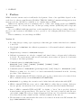
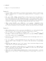
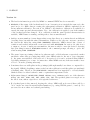
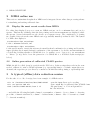
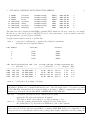
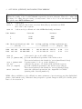
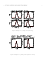
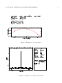
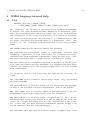
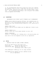
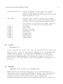
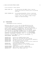
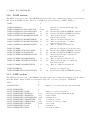
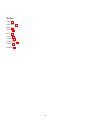
MIRA Manual - v. 1.4
Identifier - Master URL: http://www.iram.fr/
Revision: miraManual.html ,v 1.4
Date: 2005-11-14
Author: Helmut Wiesemeyer (email: [email protected])
Contributors: A. Sievers, H. Ungerechts, the MBFITS working group
Audience: everybody involved with raw data reduction at the 30m telescope
Publisher: IRAM, Grenoble
Subject and Keywords: raw data, calibration, 30m telescope
Description - about this document:
This manual describes MIRA, a Multichannel Imaging and Calibration Software for Receiver Arrays.
At present (September 2005), MIRA succeeds OTFCAL for the calibration of the new IMBFITS raw
data at the 30m telescope.
Related documents:
http://www.iram.fr/IRAMFR/GILDAS/
1 PREFACE
1
2
Preface
MIRA as in the current version is still under development. Parts of its capabilities depend on the
work done for other program libraries (CLASS90, TELCAL, PAKO). Comments and suggestions from
users are welcome, and will be a valuable tool to further improve MIRA.
MIRA in its current version is exclusively used to reduce data written in the new IMBFITS
raw data format. For old raw data, the old data processing software (OTFCAL) will be kept and
maintained.
As soon as MIRA is fully integrated into as the standard heterodyne data processing software for
the new control system, it will further evolve to provide tools for imaging with heterodyne receiver
arrays.
This is a summary of recent changes in MIRA:
Version 1.1
• For online data processing, a prototypical procedure mira_pro:reduce.mira has been commited
to the CVS.
• New default for MIRA\CAL: the calibration parameters of all frontend-backend combinations are
computed.
• Output message formats for MIRA\SCAN changed.
• Calibration parameters are already computed and issued when a chopper-wheel calibration
is loaded. For spectrometers with several basebands, mean values are given (for basebands
belonging to the same spectrum).
• Command syntax for MIRA\VIEW changed to
MIRA\VIEW [ifb] [/CAL] [/GAINS] [/PHASES] [/SIGNAL] [/MAP]
Useful defaults are provided.
• Command syntax for MIRA\SOLVE [pointing|focus] [ifb] changed to MIRA\SOLVE [ifb].
Whether a pointing is to be solved or a focus is automatically determined from the observing
procedure of the current scan.
• MIRA commands using the SIC macros in mira_pro:p_plot_*.mira can now be retrieved from
SIC’s command stack (concerns MIRA\SOLVE and MIRA\VIEW).
• MIRA\SOLVE: for pointings, the execution can be halted after the subscan fits with QUIT.
• MIRA command FIND has a new option FIND /NEW (for online data processing). Only new
data are put into the index list. If no new data are found, the index list remains unchanged.
• Lists of MIRA commands FIND and LIST: by default, a ”short” list is provided (without
frontend names and spectral lines). The previous ”long” list can be retrieved with the new
option LIST /LONG. The telescope name is suppressed in any case. Note that the scan number
is now listed in the first column, and the observation number in the last one.
• The information is the current index list can now be retrieved from the new SIC structure list
(type \MIRA\VARIABLE LIST r).
1 PREFACE
3
• Support of old raw data abandoned.
Version 1.2
• Default for MIRA command CAL is now the first frontend-backend combination. If all frontendbackend combinations are to be calibrated, the argument ALL has to be specified, i.e. CAL
ALL [/...options].
• The option /OFF of MIRA command CAL now offers several modi for the subtraction of
the reference signal in OTF maps with total-power mode. The reference signal is either a
mean of all off-measurements (option NONE, the default), an unweighted mean of the reference
measurements taken before and after the on-measurement, and weighted means (weighting by
total power or elapsed time). See the MIRA language internal help for more details.
• MIRA command WRITE, option /FEBE has a new argument:
MIRA\WRITE number
/FEBE ALL writes all frontend-backend combinations into the CLASS output file, starting with
the observation identification number (if specified, otherwise successively increased by default).
Version 1.3
• MIRA stability is improved. If, for a given scan, the imbFits file of one of the backends is faulty,
this backend will be ignored in the index list (and a warning message is issued).
• The new imbFits keywords XOFFSETi and YOFFSETi (with i = 1 to noffsets , where noffsets is
the number of offsets from the catalogue position) are accomodated in MIRA’s SCAN%DATA
section.The resulting offset is in SCAN%HEADER.
• The SIC macro reduce.mira now becomes reduceCont.mira and reduceSpec.mira. See section 2.1 for details.
• New option /ZOOM for command MIRA\VIEW. First the data is fully shown, and the interactive
cursor is called to define a rectangle to be zoomed in. The axis labels are correspondingly
updated.
• MIRA\VIEW /MAP /ZOOM can be used to plot a subset of data. In the subset display, the range
of ON positions covered by the subscan(s) is indicated.
• MIRA\CAL, option /OFF: the default weight mode for on-the-fly maps is now AVER (taking an
average of all available off-source subscans). Option NONE does not remove any off-source signal,
but concatenates the spectral basebands.
• MIRA’s SIC variable ARRAYi\%DATAj\%ISWITCH (with i frontend-backend number, j baseband
number) now becomes an array of character strings (instead of integer flags). See section 5 for
details.
1 PREFACE
4
Version 1.4
• The header information provided by MIRA’s command VIEW has been extended.
• MIRA\CAL: if the setup of the backends used for an observation is not strictly the same as for the
previous (or, for offline data processing, the subsequent) calibration, MIRA complained about
an inconsistent calibration. In version 1.4, MIRA looks whether a calibration is available for
exactly the same spectral charactersistics. If so, the calibration is applied, even if the number
of the backend part has changed. If no calibration with the same spectral characteristics is
available, MIRA issues a warning, and flags those data as uncalibrated.
• Ambigeous scan numbers: it may happen that a raw data directory contains data from different
observing dates, but with the same scan numbers. Until now, the only way out was to preselect
the data in the index list, using FIND /OBSERVED. Otherwise, MIRA entered into a state of
confusion and crashed when such a scan was read with MIRA\SCAN. In version 1.4, this is not
so anymore: in case of ambigous scan numbers, the user is asked to enter the desired observing
date (if nothing is entered, MIRA\SCAN returns to the command prompt, allowing to opt for the
solution using FIND /OBSERVED.
• The pause between pointing solutions by subscans and coadded subscans, respectively, makes
automatic online data processing impossible, since MIRA waits for the use to type continue.
So, the pause was switched off in version 1.3. In version 1.4, it can be activated using MIRA’s
logical flag doPause (yes or .true. for interactive offline MIRA sessions, if the user wants to have
a close look at the pointing subscans).
• Sometimes there are still spikes in the pointings (although usually lower than or comparable to
the signal). MIRA’s despiking routine works best after calibration, and the spikes get attributed
a blanking value. Therefore, the MIRA\SOLVE command has been upgraded to correctly handle
blanked values for either backend counts or equivalent temperature scales.
• slight syntax change for MIRA\VIEW /PHASE idPhase irec. idPhase can be one of the character
strings ON, OFF, LOAD, SKY, HOT, COLD, FLO, FHI. The specified phase is averaged across
the whole scan, unless a special record is specified with irec.
• If a backend part is disconnected, keeping the others, MIRA will work even if there will be a
”hole” in the associated frontend-backend numbers (e.g. using VESPA parts 1, 3 and 4). Not
yet tested for more than one backend part lacking.
2 MIRA ONLINE USE
2
5
MIRA online use
This section contains first thoughts how MIRA can be integrated in an online data processing scheme
for visualizing and writing calibrated data.
2.1
Display the most recent results from MIRA
For online data display, I propose to start two MIRA sessions, one for continuum data, and one for
spectra. This has the advantage that the last pointing and focus measurements are displayed, while
the spectra observed afterwards are also shown on a separate screen. The complication of opening
two graphic devices from the same MIRA session (potentially unstalbe) is thus avoided. The syntax
for online data display is
@ reduceCont iRef writeClass
for the continuum backends, and
@ reduceSpec iSpec writeClass
for the spectrometers. iref is the reference frontend-backend combination for pointing and focus fits,
ispec specifies the frontend-backend combination of the spectrum to be shown, and writeClass is
a logical flag deciding whether a CLASS file is to be written or not. I propose to set writeClass
to .false. (or no), and to leave the generation of a CLASS file to a dedicated Python script (see
below).
2.2
Online generation of calibrated CLASS spectra
MIRA should be called (scan by scan) from the NCS via a Python script that reads in the scan
needed, calibrate it, write a CLASS spectrum (e.g. spectraOdp.30m) to a default output directory.
As usual, the respective project directory contains a soft link data.30m pointing to spectraOdp.30m.
3
A typical (offline) data reduction session
For the sake of a cookbook recipe, here is an example of a MIRA session.
file in "/ncsServer/mrt/ncs/data/2005-04-06"
file out spectra.30m new
find /observed 2005-09-06 /scan 5 15
opens the input directory for reading
opens output file for calibrated data (CLASS forma
only puts scans 5 to 15 from September 6
into the index list.
... and yields the following list (with column 1 - scan number, column 2 - object, column 3 - observing
procedure, column 4 switch mode, column 5 - backend name, column 6 - date of observation, column
7 - observation number) :
3 A TYPICAL (OFFLINE) DATA REDUCTION SESSION
5
6
9
12
13
14
15
VENUS
VENUS
VENUS
IRC+10216
IRC+10216
IRC+10216
IRC+10216
calibrat
pointing
focus
calibrat
onOff
calibrat
onTheFly
beamSwitching
beamSwitching
beamSwitching
beamSwitching
beamSwitching
beamSwitching
totalPower
6
CONTI
CONTI
CONTI
4MHZ
4MHZ
4MHZ
4MHZ
2005-09-06
2005-09-06
2005-09-06
2005-09-06
2005-09-06
2005-09-06
2005-09-06
1
2
3
4
5
6
7
The same list can be displayed with MIRA command LIST, which also allows to write it to an output
file and not to the screen (option /OUTPUT), and to issue information on the frontends connected
and spectral lines observed (option /LONG).
A typical data reduction session looks like this:
scan 5
loads scan 5 (calibration), computes the calibration paramters,
and issues the following information:
FeBe Number
Frontend
Backend
1
2
3
4
A100
B100
A230
B230
CONTI
CONTI
CONTI
CONTI
idFe THotLoad TColdLoad idBe Pix recTemp sysTemp calTemp tauZenith pwv
---- [Kelvin] --------- [Kelvin] ------- [Neper] [mm]
------------------------------------------------------------------------A100 295.199
86.000 CONTI 1
78.60 480.33 228.15
7.29
10.1
B100 295.199
88.000 CONTI 1
39.91 404.02 216.94
7.31
11.9
A230 295.199
86.000 CONTI 1
289.67 1515.64 350.22
0.39
5.6
B230 295.199
86.000 CONTI 1
91.00 800.64 305.18
0.43
6.2
scan 6
loads scan 6 (a pointing on Venus)
Tip: It may happen that your index list contains observations from different days, but with the same
scan number. In that case, comand SCAN invites you to enter the wanted date of observation (format
YYYY-MM-DD). Alternatively, if you enter nothing, you return to MIRA’s command line, where you
can narrow your search criteria with FIND /OBSERVED YYYY-MM-DD.
cal all
solve 4
corrects all observations in the current scan for gains,
applies the Ta* scale and subtracts off signals.
N.B. CAL is NOT a prerequisite for solving pointings or foci.
solves the pointing measurement, using the receiver B230, plots
the results (Fig.1, 2), and writes an XML file for the control system.
Tip: Occasionally, spikes appear in the raw data. If they are stronger than the total power level, they
can be removed from the raw data with MIRA’s command DESPIKE. If they are comparable to the
total power level, you should first calibrate the pointing, then despike, and then solve the pointing fit.
3 A TYPICAL (OFFLINE) DATA REDUCTION SESSION
7
Tip: By default, MIRA’s pointing procedure halts for a while after the subscan plots, and then
displays the results of the coadded azimuth respectively elevation subscans. This is for online data
processing. For offline data processing, you may want to have a close look at the subscans. In that
case, please enter LET doPause yes.
scan 9
solve 1
scan 12
loads scan 9
solve and plot the focus for receiver B230 (Fig.3), and writes an XML
file for the control system.
loads scan 12 (a calibration for the 4MHz filterbank), and issues
FeBe Number
Frontend
Backend
1
2
A230
B230
4MHZ
4MHZ
idFe THotLoad TColdLoad idBe Pix recTemp sysTemp calTemp tauZenith pwv
---- [Kelvin] --------- [Kelvin] ------- [Neper] [mm]
------------------------------------------------------------------------A230 295.199
86.000 4MHZ
1
362.19 3018.86 240.79
0.40
5.8
B230 295.199
86.000 4MHZ
1
127.34 1658.64 213.17
0.42
6.0
scan 13
loads scan 13 (an on-off on IRC+10216)
view [1 /phases ON] plots the uncalibrated spectrum of the A230 receiver.
The text in brackets is the default for \view (uncalibrated data).
view 1 /phases OFF
You may want to look e.g. at the off-phase, too.
cal all
calibrates the spectra of both the A230 and B230 receivers.
view [1 /signal]
plots the calibrated spectrum for the A230 receiver (Fig.4).
The text in brackets is the default for \view (calibrated data).
write /febe ALL
writes the calibrated spectra into the output file for CLASS
(starting with observing number 1)
MIRA offers possibilities to plot calibration counts, gainarrays of spectrometers, raw data (individual
phases of the switch cycle), calibrated data (as spectra or pseudo-maps for OTF). For details, please
have a look at section 4.
3 A TYPICAL (OFFLINE) DATA REDUCTION SESSION
Figure 1: Example for a pointing solution (first step).
Figure 2: Example for a pointing solution (subscans coadded).
8
3 A TYPICAL (OFFLINE) DATA REDUCTION SESSION
Figure 3: Example for a focus solution.
Figure 4: Example of a calibrated spectrum.
9
4 MIRA LANGUAGE INTERNAL HELP
4
4.1
10
MIRA language internal help
CAL
MIRA\CAL [ALL|ifb] [/GAINS [/TCAL]]
[/OFF [NONE] [AVER] [EQUAL] [TIME] [TOTAL vMin vMax]]
CAL calibrates the raw data of the observations loaded with MIRA\SCAN.
By default, the first frontend-backend combination is calibrated, otherwise the frontend-backend combination number ifb, or all frontend-backend combinations if ALL is specified instead. If no option is specified,
all three calibration stages are performed (i.e. normalization by channel gains, conversion from backend counts to a temperature scale, subtraction of the off-signal with concatenation of autocorrelator basebands.
CAL /GAINS normalizes the spectral band by the gainarray.
CAL /TCAL Converts from backend counts to temperature (forward beam
brightness temperature if beam efficiciency set to forward efficiency,
otherwise main beam brightness temperature), using the TCal scale automatically determined when a "chopper wheel" calibration is loaded.
CAL /OFF subtracts the atmospheric emission as measured on the OFF position, and concatenates spectral basebands. For frequency-switched observations, the subtraction of the reference signal has to be done in CLASS
with command FOLD.
For on-the-fly data in total power mode, CAL /OFF has the following
tions:
op-
CAL /OFF NONE does not subtract the reference signal, only concatenates
spectral basebands.
CAL /OFF AVER uses as reference signal for off subtraction the unweighted mean of all available reference measurements. This is the default.
CAL /OFF EQUAL uses as reference signal an unweighted mean of the offmeasurements taken before respectively after the on-subscan.
CAL /OFF TIME uses as reference signal a weighted mean of the off-measurements taken before respectively after the on-subscan. The first reference has a weight decreasing with the time elapsed between the on-thefly record and the first reference measurement (and the weight of the
second reference increases correspondingly).
CAL /OFF TOTAL vMin vMax uses as reference signal a weighted mean
value
4 MIRA LANGUAGE INTERNAL HELP
of the off-measurements taken before respectively after the on-subscan.
The weighting is done in a way to ensure that the total power of the onthe-fly record equals the total power of the reference signal. A spectral
line contributing significantly to the total power can be masked
with the arguments vMin and vMax.
4.2
DESPIKE
MIRA\DESPIKE [ifb] [/PIXEL [ipix]] [/ITERATE niter] [/INTERPOLATE]
DESPIKE removes spikes from spectra, OTF data, and continuum drifts, respectively. If the frontend-backend identification number ifb is not
specified, the first frontend-backend combination of the current scan is
despiked.
DESPIKE /PIXEL [ipix]
Allows to specify the pixel number ipix (for HERA data). Default is pixel 1.
DESPIKE /ITERATE niter
Allows to remove up to niter spikes (default is niter = 10).
DESPIKE /INTERPOLATE
Instead of attributing the blanking value to the removed spikes, the
mean value of the next neighbours is used. Not yet implemented.
4.3
FILE
MIRA\FILE IN|OUT name [NEW] [/CLASS] [/MBFITS]
Selects the input directory and output files.
FILE IN name
defines the input directory
FILE OUT name [NEW] defined the output file;
initializes a file if NEW is given.
FILE /CLASS Opens a CLASS type file for output (default).
FILE /MBITS Converts IMBFITS raw data to MBFITS raw data.
Not yet implemented.
11
4 MIRA LANGUAGE INTERNAL HELP
4.4
FIND
MIRA\FIND [/BACKEND] [/FRONTEND] [/LINE] [/OBSERVED] [/PROCEDURE]
[/SCAN] [/SOURCE] [/TELESCOPE] [/NEW] [/SWITCHMODE]
FIND performs a search in the input directory to build a new index,
according to selection criteria defined by one or more of the following
options. The index list (as desribed in the help for command MIRA\LIST).
/BACKEND name
/FRONTEND receiver
/LINE
transition
/OBSERVED startDate [endDate]
/PROCEDURE procedure
/SCAN i1 [i2]
/SOURCE object
/TELESCOPE antenna
/NEW
/SWITCHMOD switch
4.5
Searches for data from backend name.
Searches for data from a given receiver.
Search for data of spectral line transition.
Searches for data observed between startDate
and endDate. If endDate is not specied, looks
only for data observed the day of startDate.
Date format is YYYY-MM-DD (e.g. 2005-09-29).
Searches for data of a given observing
procedure (e.g. pointing, focus, onOff,
calibration,...).
Searches for data from scans i1 to i2 (or only
scan i1 if i2 not specified).
Searches for data from source object.
Searches for data from telescope antenna.
Searches for new data written to the input
directory; the new index list will only
contain new data. If no new data are found,
the current index list remains unchanged. For
online data processing at the telescope.
Searches for observations done with switchmode
switch (e.g. wobbler, beamSwitching).
LIST
MIRA\LIST [/OUTPUT listfile] [/LONG]
LIST writes the current index list to the screen:
column 1 :
scan number
column 2 :
source name
column 3 :
observing procedure
column 4 :
switch mode
column 5 :
backend name
column 6 :
observing date (format YYYY-MM-DD)
column 7 :
running index
12
4 MIRA LANGUAGE INTERNAL HELP
LIST /OUTPUT listfile
Writes the index list into output file listfile,
instead of writing to the screen. No default
provided (LIST /OUTPUT has the same action as LIST).
Default extension is .lis
LIST /LONG
Provides a more complete listing. Each frontendbackend combination is listed. Information which is
the same for all frontend-backend combinations is
only written once per scan (all columns except for
the spectral line name and the frontend name).
scan number
source name
spectral line name
observing procedure
switch mode
frontend name
backend name
observing date
running index
column
column
column
column
column
column
column
column
column
4.6
1:
2:
3:
4:
5:
6:
7:
8:
9:
SCAN
MIRA\SCAN scan
Loads a scan from the current index list. ALL frontend-backend combinations
used are loaded. A list of identification numbers for the frontend-backend
combinations is issued. For calibrations, MIRA\SCAN also computes the
calibrations parameters, and writes them to the screen. The calibration
parameters for VESPA basebands are individually computed; however, the
screen output is for mean values across all basebands corresponding to one
spectrum.
4.7
SOLVE
MIRA\SOLVE [ifb] [/PIXEL ipix] [/BINNING nbin]
SOLVE retrieves the pointing respectively focus corrections from the
observing procedure loaded with MIRA\SCAN. By default, the first frontend
connected to the continuum backend is used, otherwise number ifb. The
results are written to the output device, and to output files
miraResultsPointing.xml respectively miraResultsFocus.xml for further use
13
4 MIRA LANGUAGE INTERNAL HELP
by the telescope’s control system.
4.8
SOLVE /PIXEL ipix
For observations with HERA. Allows to specify
another pixel than the reference pixel for pointing
and focus.
SOLVE /BINNING nbin
For pointing measurements, allows to smooth the
azimuth and elevations drifts (for weak pointing
sources). nbin is the number of dumps averaged
(simple box window smoothing).
VARIABLE
MIRA\VARIABLE section|* read|write
Generates a SIC copy of one of the following MIRA data sections
(wildcard permitted, activates all sections), for read (default)
ow write access. For further documentation on MIRA’s data structure,
please consult section 5 of the MIRA manual. The section MON consists of
SIC structures MON%HEADER and MON%DATA. Each frontend-backend
combination has its own GAINS and REDUCE section (e.g. GAINS1, REDUCE3,
etc.). The sections SCAN, FEBE, and DATA consist of header and data
structures for each frontend-backend combination, e.g. SCAN1%HEADER,
SCAN1%DATA, FEBE2%HEADER, FEBE3%DATA, and so on. The DATA and HEADER
structures of section ARRAY are written for each baseband, e.g.
ARRAY1%HEADER1, ARRAY2%DATA3, etc.
VARIABLE
VARIABLE
VARIABLE
VARIABLE
VARIABLE
PRIM
SCAN
FEBE
ARRAY
DATA
VARIABLE MON
VARIABLE GAINS
VARIABLE CHOICE
VARIABLE REDUCE
VARIABLE LIST
Retrieves the IMBFITS primary header.
Same for the scan header and table sections.
Information related to the frontend-backend combination.
Raw data headers and data sections.
For calibrated raw data, and monitor points interpolated
at the backend timestamps.
Monitoring headers and table sections.
Calibration parameter for each frontend-backend
combination.
Search options for MIRA’s command FIND.
MIRA internal flags for calibration history.
Entries of the current index list.
14
4 MIRA LANGUAGE INTERNAL HELP
4.9
VIEW
MIRA\VIEW [ifb] [/CAL] [/GAINS] [/PHASES [phaseId] [irec]] [/SIGNAL [idu
[/MAP] [/ZOOM]
VIEW is MIRA’s command for plotting the data of frontend-backend
combination number ifb (default is 1). The item to be plotted is specified
by one of the following options. Otherwise, the following defaults are
provided: VIEW /CAL for chopper-wheel calibrations, VIEW /PHASES for all
uncalibrated data, VIEW /SIGNAL for calibrated data (at least off
subtracted) from a single position, respectively VIEW /MAP for OTF maps.
VIEW /CAL
For calibrations only. Plots the counts from the loads (sky, ambient,
cold, respectively) versus time (for continuum backends. For spectral line
backends, plots the subscan average of the dumps from the corresponding
loads versus frequency.
VIEW /GAINS
Plots the gainarray currently in use. For spectrometers only.
VIEW /PHASES [phaseId] [irec]
Plots the uncalibrated data against time (for continuum backends)
respectively frequency and record number (for spectrometers), using
phase phaseId (according to the observing procedure viewed, it defaults to O
SKY, or FHI). By default, the scan average of all phases iphase in shown,
otherwise record number irec.
VIEW /SIGNAL [idump]
Plots calibrated data, as time series (for continuum drifts) respectively
spectra (for spectrometers). For OTF maps, record number idump can be
specified to plot a single spectrum.
VIEW /MAP
Plots a pseudo-map (data values versus velocity and record number) for
calibrated OTF data.
VIEW /ZOOM
Plots and calls the interactive cursor to define a region for a zoom. Use
the cursor to define the lower left and upper right corner (order does not
matter).
15
5 MIRA / SIC VARIABLES
4.10
16
WRITE
MIRA\WRITE [number] [/FEBE ALL|ifb] [/PIXEL ipix] [/SUBSCANS isub]
Writes calibrated data to a CLASS file (respectively raw data to a
MBFITS file, not yet implemented, see help for MIRA\FILE). The number of
the spectrum (or continuum drift) written can be specified, otherwise it is
successively increased, starting at 1.
WRITE [number] /FEBE ALL|ifb
Specifies the frontend-backend combination to be written. Default is 1.
Writes CLASS spectra for all frontend-backend combinations in current index
(starting with observation identification ’number’ if specified).
WRITE /PIXEL ipix
For HERA data: spectra from pixel ipix are written (default pixel 1).
WRITE /SUBSCANS isub
For continuum drifts and OTF maps: only data from subscan isub are written.
5
MIRA / SIC variables
Most of the variables in the internal MIRA structure can be copied to and examine (e.g. plotted with
GREG) as SIC variables. MIRA provides the following commands for defining and initialising these
variables. For an explanation of the sections and their contents, I also refer to the document ”MultiBeam FITS Raw Data Format”, revision 1.4. Variables derived from WCS ( = world coordinate
system) FITS keywords have their leading number appended to the end of the keywords’ names, for
the sake for compatibility with FORTRAN (e.g. CRVL4_1 instead of 1CRVL4).
There are MIRA variables that are useful to customize plotting routines for online respectively offline
use of MIRA, or for defining tolerance limits for tracking errors (to be done). In version 1.4, there is
only one such variable:
doPause
! Logical GLOBAL
which can be set to .true. or .false. with
let doPause yes
respectively
let doPause no
It is used to halt the execution of MIRA\SOLVE until the user types continue.
5 MIRA / SIC VARIABLES
17
retrieves primary header as SIC variables for
reading (default) or writing.
scan r [w]
same for the scan header and table sections
febe r [w]
frontend-backend header and table sections
array r [w]
arraydata headers and table sections
data r [w]
data headers and table sections
mon r [w]
monitoring headers and table sections
gains r [w]
MIRA variables
choice r [w] search options for MIRA command find
reduce r [w] MIRA internal flags for calibration history
var prim r [w]
var
var
var
var
var
var
var
var
Here is a listing of the corresponding SIC variables. The array dimensions are specified by the following
parameters:
nfb
npix
nbd
ncpb
nchan
noff
nrec
nph
nsubsc
nsubr
nslow
nfast
number
number
number
number
number
number
number
number
number
number
number
number
of
of
of
of
of
of
of
of
of
of
of
of
frontend-backend combinations
pixels
basebands
spectral channels per baseband
spectral channels (concatenated basebands)
off positions from catalogue position
records (= backend data)
phases (e.g. 2 = on, off)
subscans
subreflector monitor points
antenna monitor points (slow rate)
antenna monitor points (fast rate)
Variable types are denoted as S (structure), I (integer), R (real, single precision), D (real, double
precision), C (character string) and L (logical).
Caveats: (1) Neither the MIRA data structures nor the corresponding SIC structures are exactly
mapped from the MBFITS V1.54 file definition. However, I tried to keep them as close as possible. (2)
Not all of the following items are already copied from the IMBFITS file to SIC variables (even if the
SIC variable is declared).
5 MIRA / SIC VARIABLES
5.1
18
PRIMARY section
PRIM
S
PRIM%HEADER
PRIM%HEADER%MBFTSVER
PRIM%HEADER%CREATOR
PRIM%HEADER%ORIGIN
PRIM%HEADER%TELESCOP
PRIM%HEADER%EXTEND
PRIM%HEADER%BITPIX
PRIM%HEADER%SIMPLE
PRIM%HEADER%NAXIS
S
C*11
C*32
C*32
C*13
L
I
L
I
5.2
MBFITS version
Softwrae (including version)
Organisation or Institution
Telescope Name
SCAN section
General scan information.
SCAN
S
SCAN%HEADER
SCAN%HEADER%ZFLX
SCAN%HEADER%ECEC
SCAN%HEADER%IE
SCAN%HEADER%AW
SCAN%HEADER%AN
SCAN%HEADER%NPAE
SCAN%HEADER%CA
SCAN%HEADER%IA
SCAN%HEADER%NFEBE
SCAN%HEADER%WOBMODE
SCAN%HEADER%WOBCYCLE
SCAN%HEADER%WOBDIR
SCAN%HEADER%WOBTHROW
S
R
R
R
R
R
R
R
R
I
C*20
R
C*4
D
deg
SCAN%HEADER%WOBUSED
SCAN%HEADER%TRANFOCU
L
I
m
SCAN%HEADER%TRANFREQ
SCAN%HEADER%TRANDIST
SCAN%HEADER%ZIGZAG
SCAN%HEADER%CROCYCLE
SCAN%HEADER%SCANPAR1
SCAN%HEADER%SCANPAR2
SCAN%HEADER%SCANSKEW
I
I
L
C*20
D
D
D
deg
deg
deg
deg
deg
deg
deg
deg
sec
Hz
m
user def.
Pointing coefficient (Flexure)
Pointing coefficient (P8)
Pointing coefficient (P7)
Pointing coefficient (-P4)
Pointing coefficient (P5)
Pointing coefficient (P3)
Pointing coefficient (P2)
Pointing coefficient (P1)
number of frontend-backend combinations
wobbler mode (SQUARE/TRIANGULAR)
wobbler period
wobbler throw direction
wobbler throw (can also be used for beam
switching)
Wobbler used ?
(optional, HOLO) transmitter offset from prime
focus
(optional, HOLO) transmitter frequency
(optional, HOLO) transmitter distance
(optional, OTF/RASTER) Scan in zigzag ?
CAL/REF/ON loop string
(optional) spare scan parameter
(optional) spare scan parameter
(optional, OTF/RASTER) offset in scan
direction between lines
5 MIRA / SIC VARIABLES
19
SCAN%HEADER%SCANYSPC
D
user def.
SCAN%HEADER%SCANXSPC
D
user def.
SCAN%HEADER%SCANTIME
SCAN%HEADER%SCANXVEL
SCAN%HEADER%SCANLEN
SCAN%HEADER%SCANRPTS
D
D
D
I
user def.
user def.
user def.
SCAN%HEADER%SCANLINE
SCAN%HEADER%SCANDIR
SCAN%HEADER%SCANGEOM
SCAN%HEADER%SCANMODE
SCAN%HEADER%SCANTYPE
SCAN%HEADER%DISTANCE
SCAN%HEADER%ORBEQUNX
SCAN%HEADER%ORBEPOCH
SCAN%HEADER%ECCENTR
SCAN%HEADER%INCLINAT
SCAN%HEADER%OMEGA
SCAN%HEADER%LONGASC
SCAN%HEADER%PERIDIST
SCAN%HEADER%PERIDATE
SCAN%HEADER%MOVEFRAM
I
C*4
C*20
C*20
C*20
D
D
D
D
D
D
D
D
D
L
SCAN%HEADER%CALCODE
SCAN%HEADER%LATOBJ
SCAN%HEADER%LONGOBJ
SCAN%HEADER%LONGOFF
SCAN%HEADER%LATOFF
SCAN%HEADER%OBJECT
SCAN%HEADER%LATPOLE
SCAN%HEADER%LONPOLE
SCAN%HEADER%CRVAL1
SCAN%HEADER%CRVAL2
SCAN%HEADER%EQUINOX
SCAN%HEADER%RADECSYS
C*4
D
D
D
D
C*10
D
D
D
D
R
C*32
SCAN%HEADER%CTYPE1
SCAN%HEADER%CTYPE2
SCAN%HEADER%ETUTC
SCAN%HEADER%GPSTAI
SCAN%HEADER%TAIUTC
SCAN%HEADER%UT1UTC
SCAN%HEADER%NOBS
SCAN%HEADER%LST
SCAN%HEADER%MJD
C*8
C*8
D
D
D
D
I
D
D
SCAN%HEADER%DATE OBS
SCAN%HEADER%SCANNUM
SCAN%HEADER%OBSID
SCAN%HEADER%PROJID
SCAN%HEADER%SITEELEV
C*23
I
C*12
C*12
R
AU
Julian days
AU
Julian days
deg
deg
deg
deg
deg
deg
deg
deg
Julian years
s
s
s
s
s
day
m
(optional, OTF/RASTER) step
between scan/raster lines
(optional, OTF/RASTER) step along line
between samples
(optional, OTF) time for one line
(optional, OTF) tracking rate along line
(optional, OTF/RASTER) line length
(optional) number of repeats of each scan line.
Default 1.
(optional) number of lines in a scan. Default 1.
(optional) scan direction
Scan geometry
Mapping mode
Scan astronomical type
geocentric distance
Elements equinox: J2000.0 or B1950.0
EPOCH, Epoch of orbital elements
EC, Eccentricity
IN, Inclination
W, Angle from ascending node to perihelion
OM, Longitude of ascending node (in degrees)
QR, perihelion distance
TP, Full Julian date of perihelion passage
True if tracking a moving frame. If true,
the above orbital elements are stored.
Calibrator code
Source latitude in native frame.
Source longitude in native frame.
Longitude offset from catalogue position.
Latitude offset from catalogue position.
Source name.
Basis latitude of native pole.
Native longitude of celestial pole.
Native frame zero in basis system (long.)
Native frame zero in basis system (lat.)
Equinox
additional system definition for ecliptic/
equatorial coordinates
Basis system (longitude) XLON-SFL
Basis system (latitude) XLAT-SFL
Ephemeris Time - UTC time translation
GPS time - TAI translation
TAI-UTC time translation
UT1-UTC time translation
Number of observations in this scan
Local apparent sidereal time (scan start)
Scan start time (modified Julian date) in
TIMESYS system
Scan date/time (in TIMESYS system)
Scan number
Observer and Operator initials
Project ID
Observatory elevation
5 MIRA / SIC VARIABLES
20
SCAN%HEADER%SITELONG
SCAN%HEADER%SITELAT
SCAN%HEADER%TELESCOP
D
D
C*13
SCAN%DATA
SCAN%DATA%LONGOFF
SCAN%DATA%LATOFF
SCAN%DATA%FE
S
noff D
noff D
nfb I
SCAN%DATA%BE
nfb I
5.3
deg
deg
Observatory longitude
Observatory latitude
Telescope name
deg
deg
longitude offset from catalogue position
latitude offset from catalogue position
frontend ID of each frontend-backend combination
0 = unknown
1 = A100 2 = B100
3 = C150 4 = D150
5 = A230 6 = B230
7 = C270 8 = D270
9 = HERA 10 = HERB
backend ID of each frontend-backend combination
0 = unknown 1 = continuum
4 = VESPA
5 = WILMA
7 = 4MHz
FEBE section
There is one FEBE (=frontend-backend description) section per frontend-backend combination. The
following list is for frontend-backend combination 1 (the corresponding items for combination 2 were
FEBE2%HEADER and FEBE2%DATA, and so on).
FEBE1
S
FEBE1%HEADER
FEBE1%HEADER%ZFLXRX
FEBE1%HEADER%ECECRX
FEBE1%HEADER%IERX
FEBE1%HEADER%CARX
FEBE1%HEADER%IARX
FEBE1%HEADER%FRQTHROW
FEBE1%HEADER%NPHASES
FEBE1%HEADER%SWTCHMOD
FEBE1%HEADER%NUSEFEED
FEBE1%HEADER%FEBEFEED
FEBE1%HEADER%FEBEBAND
S
R
R
R
R
R
R
I
C*20
I
I
I
FEBE1%HEADER%DEWANG
FEBE1%HEADER%DEWRTMOD
FEBE1%HEADER%DATE OBS
R
C*5
C*23
FEBE1%HEADER%SCANNUM
FEBE1%HEADER%FEBE
I
C*17
deg
deg
deg
deg
deg
Hz
deg
Pointing Coefficient (receiver), adds to ZFLX
Pointing Coefficient (receiver), adds to ECEC (P8)
Pointing Coefficient (receiver), adds to IE (P7)
Pointing Coefficient (receiver), adds to CA (P2)
Pointing Coefficient (receiver), adds to
Frequency switching throw
number of switch phases in a switch cycle
Switch mode
number fo feeds in use.
total number of feeds.
total number of basebands for this frontend-backend
combination
dewar angle
dewar tracking system
observing date (Y2K format with time) in TIMESYS
system (scan start)
scan number
frontend-backend combination identification
5 MIRA / SIC VARIABLES
21
FEBE1%DATA
FEBE1%DATA%GAINELE1
S
nbd R
deg
FEBE1%DATA%GAINELE2
nbd R
deg
npix × nbd R
npix × nbd R
npix R
npix × nbd R
npix × nbd R
npix × nbd R
npix × nbd R
npix × nbd R
npix R
npix C*1
I
npix D
npix D
npix C*1
npix I
FEBE1%DATA%GAINIMAG
FEBE1%DATA%FLATFIEL
FEBE1%DATA%BOLCALFC
FEBE1%DATA%ANTGAIN
FEBE1%DATA%HPBW
FEBE1%DATA%ETAFSS
FEBE1%DATA%BEAMEFF
FEBE1%DATA%APEREFF
FEBE1%DATA%POLA
FEBE1%DATA%POLTY
FEBE1%DATA%REFFEED
FEBE1%DATA%FEEDOFFX
FEBE1%DATA%FEEDOFFY
FEBE1%DATA%DATA%FEEDTYPE
FEBE1%DATA%USEFEED
5.4
Jy/counts
K/Jy
deg
deg
deg
deg
Gain-elevation correction parameter 1
(see MBFITS manual)
Gain-elevation correction parameter 2
(see MBFITS manual)
Gain ratio image/signal sideband
receiver array flat field (relative gains)
bolometer calibration factor
Antenna gain
Half-power beam width
forward efficiency
beam efficiency
aperture efficiency
feed orientation
feed type (X, Y, L, R)
feed number of reference feed
feed x offset
feed y offset
feed type (see MBFITS manual)
list of feeds which are in use
ARRAY section
There is one ARRAY (= receiver array description) section per frontend-backend combination and per baseband. The following list is for frontend-backend combination 1 and baseband 1 (the corresponding structure names for frontend-backend combination 2 were FEBE2%HEADER1 and FEBE2%DATA1, respectively
FEBE2%HEADER2 and FEBE2%DATA2 for baseband 2, and so on).
ARRAY1
S
ARRAY1%HEADER1
ARRAY1%HEADER1%VSYS4R 2
ARRAY1%HEADER1%VSOU4R 2
ARRAY1%HEADER1%SOBS4R 2
ARRAY1%HEADER1%SPEC4R 2
ARRAY1%HEADER1%CD4R 21
ARRAY1%HEADER1%CUNI4R 2
ARRAY1%HEADER1%CRVL4R 2
ARRAY1%HEADER1%CRPX4R 2
ARRAY1%HEADER1%CTYP4R 2
ARRAY1%HEADER1%WCSNM4R
ARRAY1%HEADER1%SOBS4F 2
ARRAY1%HEADER1%SPEC4F 2
ARRAY1%HEADER1%CD4F 21
ARRAY1%HEADER1%CUNI4F 2
S
R
R
C*8
C*8
D
C*8
D
R
C*8
C*8
C*8
C*8
D
C*8
km/s
km/s
’TOPOCENT’
e.g. ’LSRK’
km/s
’km/s’
km/s
e.g. ’VARD-FRQ’
e.g. ’LsrkVRad’
’TOPOCENT’
e.g. ’LSRK’
Hz
’Hz’
observer velocity in rest frame
source velocity in rest frame
observing frame
standard of rest frame for velocities
velocity channel separation
Unit
velocity at reference channel
reference channel
velocity axis for col.3
axis name
observing frame
standard of rest for frequencies
channel separation
Unit
5 MIRA / SIC VARIABLES
22
ARRAY1%HEADER1%CRVL4F 2
D
Hz
ARRAY1%HEADER1%CRPX4F 2
ARRAY1%HEADER1%CTYP4F 2
ARRAY1%HEADER1%WCSNM4F
ARRAY1%HEADER1%CD3A 11
ARRAY1%HEADER1%CRVL4 1
ARRAY1%HEADER1%CRPX4 1
ARRAY1%HEADER1%CTYP4 1
ARRAY1%HEADER1%SBSEP
ARRAY1%HEADER1%SIDEBAND
ARRAY1%HEADER1%RESTFREQ
ARRAY1%HEADER1%TRANSITI
ARRAY1%HEADER1%MOLECULE
ARRAY1%HEADER1%BANDWID
ARRAY1%HEADER1%FREQRES
ARRAY1%HEADER1%CHANNELS
ARRAY1%HEADER1%DATE OBS
ARRAY1%HEADER1%OBSNUM
ARRAY1%HEADER1%SCANNUM
ARRAY1%HEADER1%BASEBAND
ARRAY1%HEADER1%FEBE
R
C*8
C*8
I
I
I
C*8
D
C*3
D
C*20
C*20
D
D
I
C*23
I
I
I
C*17
Hz
’FREQ-FRQ’
e.g. ’LsrkFreq’
ARRAY1%DATA1%ISWITCH
ARRAY1%DATA1%MJD
ARRAY1%DATA1%DATA
’PIX-INDX’
Hz
Hz
Hz
Hz
frequency at reference channel in
rest frame
reference channel.
frequency axis for col. 3
axis name
pixel index separation = 1
pixel index value at this position = 1
ref. position = 1
Pixel/feed index in USEPIX array
sideband separation
main sideband (USB or LSB)
rest frequency of line (optional)
main line transition (optional)
main line molecule (optional)
bandwidth for this band
frequency resolution
number of channels for this baseband
observation start in TIMESYS system
observation number
scan number
baseband number
frontend-backend combination ID
nrec C*4
nrec D
npix × ncpb × nrec × nph R
day
integration type
NONE
ON
OFF
LOAD SKY
HOT
COLD
FHI
FLO
MJD at integration midpoint
in TIMESYS system
backend data
5 MIRA / SIC VARIABLES
5.5
23
DATA section
There is one DATA section per frontend-backend combination. The following list is for frontend-backend
combination 1 (the corresponding structure names for combination 2 were DATA2%HEADER and
DATA2%DATA, and so on). Data associated parameters are interpolated from the monitor data (next
section) at the MIDTIME timestamp of the backend data.
DATA1%HEADER
DATA1%HEADER%CHANNELS
DATA1%HEADER%OBSTATUS
DATA1%HEADER%DPBLOCK
DATA1%HEADER%OBSTYPE
DATA1%HEADER%LST
DATA1%HEADER%DATE OBS
DATA1%HEADER%OBSNUM
DATA1%HEADER%SCANNUM
DATA1%HEADER%FEBE
S
I
C*10
L
C*1
D
C*23
I
I
C*17
s
DATA1%DATA%AZIMUTH
DATA1%DATA%BASLONG
nrec D
nrec D
deg
deg
DATA1%DATA%BASLAT
nrec D
deg
DATA1%DATA%CBASLONG
nrec D
deg
DATA1%DATA%CBASLAT
nrec D
deg
nrec D
nrec × 3 D
nrec × 3 D
nrec D
nrec I
nrec D
nrec D
nrec D
nrec D
deg
mm
mm
s
DATA1%DATA%MLATPOLE
DATA1%DATA%MCRVAL1
DATA1%DATA%MCRVAL2
DATA1%DATA%MIDTIME
nrec
nrec
nrec
nrec
D
D
D
D
deg
deg
deg
day
DATA1%DATA%MJD
nrec D
day
DATA1%DATA%ELEVATIO
DATA1%DATA%DFOCUS X Y Z
DATA1%DATA%FOCUS X Y Z
DATA1%DATA%INTEGTIM
DATA1%DATA%INTEGNUM
DATA1%DATA%LST
DATA1%DATA%LONGOFF
DATA1%DATA%LATOFF
DATA1%DATA%MLONPOLE
DATA1%DATA%NINTS
nrec I
s
deg
deg
deg
number of channels (for concatenated basebands)
Observation o.k. ? (OK/ABORT)
Data blocking ?
observation type (CAL, REF, ON, HOT, COLD, SKY)
Local apparent sidereal time (obs. start)
observation start in TIMESYS system
observation number
scan number
frontend-backend identification
azimuth inc. wobbler offsets
actual long. in astronomical basis frame,
inc. wobbler offsets
actual lat. in astronomical basis frame,
inc. wobbler offsets
commanded long. in astr. basis frame,
inc. wobbler offsets
commanded lat. in astr. basis frame,
inc. wobbler offsets
elevation inc. wobbler offsets
(opt.) focus offsets X, Y, Z (subrefl. position)
focus (subreflector position) X, Y, Z
integration time
integration point number
local apparent sidereal time
long. offset from source in user native frame
lat. offset from source in user native frame
(opt.) longitude of basis celestial pole in
body system
(opt.) basis latitude of body frame pole
(opt.) body apparent long. in basis system
(opt.) body apparent lat. in basis system
MJD at integration midpoint in TIMESYS
system
MJD at integration endpoint in TIMESYS
system
integrations in block
5 MIRA / SIC VARIABLES
24
DATA1%DATA%PHI X Y Z
nrec D
DATA1%DATA%PC 11
DATA1%DATA%PC 12
DATA1%DATA%PC 21
DATA1%DATA%PC 22
DATA1%DATA%PARANGLE
DATA1%DATA%SUBSCAN
DATA1%DATA%OTFDATA
Phi (subreflector rotation)
X, Y, Z (see MBFITS manual)
matrix elements of
transformation from pixel
coordinates to intermediate
pixel coordinates
(projection of user frame)
deg
parallactic angle
subscan number of data point
OTF data with basebands
concatenated and off subtracted
single pointing data, basebands
concatenated and off subtracted
D
D
D
D
nrec D
nrec I
npix × nchan × nrec R
counts, TA∗ [K]
npix × nch R
counts, TA∗ [K]
DATA1%DATA%RDATA
5.6
deg
MONITOR section
The MONITOR section describes all parameters associated with the data. MONITOR data are recorded
independently from the backend data (DATA section). The interpolation of data associated parameters at
the backend timestamps is written into the data substructure of the DATA section (see above).
MON
MON%HEADER
MON%HEADER%DATE OBS
MON%HEADER%FOCOBS X Y Z
MON%HEADER%IAOBS CAOBS IEOBS
MON%HEADER%OBSNUM
MON%HEADER%SCANNUM
S
S
C*23
3D
3D
I
I
mm
arcsec
observing date in TIMESYS
system
X,Y,Z focus correction
Pointing corrections, to be added
to IA (P1), CA (P2) and IE (P7).
In old 30m control system terms:
IAOBS = NULA,
CAOBS = COL*,
IEOBS = NULE
observation number
scan number
5 MIRA / SIC VARIABLES
25
MON%DATA
MON%DATA%REFRACTIO
MON%DATA%THOTCOLD
MON%DATA%TAMB P HUMID
S
D
2D
3D
arcsec
K
C, hPa, %
MON%DATA%ANTENNA AZ EL
2D
deg
MON%DATA%LONGOFF
nslow D
deg
MON%DATA%LATOFF
nslow D
deg
MON%DATA%BASLONG
nslow D
deg
MON%DATA%BASLAT
nslow D
deg
MON%DATA%PARANGLE
MON%DATA%PHI X Y Z
nslow D
nsubr × 3 D
deg
deg
MON%DATA%FOCUS X Y Z
nsubr × 4 D
mm
mm
mm
day
MON%DATA%DFOCUS X Y Z
nsubr × 3 D
mm
MON%DATA%TRACKING AZ EL
nfast × 2 D
deg
MON%DATA%ENCODER AZ EL
nfast × 3 D
deg
deg
day
MON%DATA%MJD
nslow D
day
refraction correction
hot & cold load temperature
ambient temperature,
pressure and rel. humidity
SAZM & SELV from old
control system
long. offset from source in
user native frame
lat. offset from source in
user native frame
actual long. in astronomical
basis frame, inc. wobbler
offsets
actual lat. in astronomical
basis frame, inc. wobbler
offsets
parallactic angle
Phi (subrefl. rotation) X, Y, Z
(see MBFITS manual)
focus offsets and timestamp:
X subreflector position
Y subreflector position
Z subreflector position
MJD timestamp in IMBF–
subreflector binary table
focus (subreflector position)
offsets X, Y, Z
antenna tracking errors in
azimuth and elevation
encoder azimuth & elevation
and timestamp
encoder azimuth
encoder elevation
MJD time of IMBF–antenna
binary table (fast track)
MJD time of IMBF–antenna
binary table (slow track)
5 MIRA / SIC VARIABLES
5.7
26
GAINS section
The GAINS section is not a part of the MBFITS raw-data format, and contains information relevant to
data calibration (together with the weather data, that are written to the MONITOR section). There is a
separate GAINS section for each frontend-backend combination (i.e. GAINS1, GAINS2 etc.).
GAINS1%PCOLD
GAINS1%PHOT
GAINS1%PSKY
GAINS1%LCALOF
GAINS1%BCALOF
GAINS1%TAUZEN
GAINS1%TAUZENIMAGE
GAINS1%TATMS
GAINS1%TATMI
GAINS1%TSYS
GAINS1%TRX
GAINS1%H2OMM
GAINS1%GAINARRAY
GAINS1%FEBE
5.8
nbd × npix × ncpb D
nbd × npix × ncpb D
nbd × npix × ncpb D
D
D
nbd × npix D
nbd × npix D
nbd × npix D
nbd × npix D
nbd × npix D
nbd × npix D
nbd × npix D
nbd × npix × ncpb D
C*17
deg
deg
Np
Np
K
K
K
K
mm
backend count rate of cold load
backend count rate on ambient load
backend count rate on sky
longitude offset for sky measurement
latitude offset for sky measurement
zenith opacity
zenith opacity in image band
atmospheric emission temperature
atmospheric emission temperature (image band)
system temperature
receiver temperature
precipitable water vapour
gain array (= PHOT−PSKY)
frontend-backend identification
CHOICE section
The CHOICE section is not a part of the MBFITS raw-data format, and describes the selection criteria for
MIRA’s find command.
CHOICE
CHOICE%TELESCOPE
CHOICE%OBJECT
CHOICE%SCAN1
CHOICE%SCAN2
CHOICE%PROCEDURE
CHOICE%DATE OBS1
CHOICE%DATE OBS2
CHOICE%TRANSITION
CHOICE%FRONTEND
CHOICE%BACKEND
5.9
S
C*13
C*20
C*4
C*4
C*8
C*23
C*23
C*20
C*8
C*8
first scan of selected scan range
last scan of selected scan range
observing procedure
starting date for selection
end date for selection
spectral line name
frontend selection
backend selection
REDUCE section
The REDUCE section is not a part of the MBFITS raw-data format, and contains MIRA-internal flags
describing the calibration history. There is one REDUCE section per frontend-backend combination, i.e.
REDUCE1, REDUCE2, etc.
REDUCE1
REDUCE1%DESPIKE DONE
REDUCE1%BASE DONE
REDUCE1%CALIBRATION DONE
S
L
L
3I
Data despiked (yes/no) ?
Baseline subtracted (yes/no) ?
Calibration done ?
(1) Normalized by gainarray (yes /no) ?
(2) Backend count rates (no) or temp. scale (yes) ?
(3) Off signal subtracted (yes /no) ?
5 MIRA / SIC VARIABLES
5.10
27
RAW section
The RAW section is not part of the MBFITS raw-data format, and contains time stamps for subscan start
and end in the IMBF raw-data. There is one RAW section per subscan (i.e. RAW1, RAW2,...).
RAW1
S
RAW1%ANTENNA
RAW1%ANTENNA%SUBSCANTYPE
RAW1%ANTENNA%SUBSCANSTART
RAW1%ANTENNA%SUBSCANEND
RAW1%ANTENNA%SEGMENTXSTART
S
C*40
D
D
D
day
day
deg
RAW1%ANTENNA%SEGMENTXEND
RAW1%ANTENNA%SEGMENTYSTART
D
D
deg
deg
RAW1%ANTENNA%SEGMENTYEND
D
deg
RAW1%SUBREF
RAW1%SUBREF%SUBSCANSTART
RAW1%SUBREF%SUBSCANEND
RAW1%SUBREF%SEGMENTXSTART
S
D
D
D
day
day
deg
RAW1%SUBREF%SEGMENTXEND
RAW1%SUBREF%SEGMENTYSTART
D
D
deg
deg
RAW1%SUBREF%SEGMENTYEND
D
deg
structure for subreflector monitoring data
subscan start (MJD in TIMESYS system)
subscan end (MJD in TIMESYS system)
offset at subscan start on abscissa in
user native system
offset on abscissa at subscan end
offset at subscan start on ordinate in
user native system
offset on ordinate at subscan end
RAW1%BACKEND
RAW1%BACKEND%SUBSCANSTART
S
D
day
structure for backend data
subscan start (MJD in TIMESYS system)
5.11
structure for antenna monitoring data
subscan type
subscan start (MJD in TIMESYS system)
subscan end (MJD in TIMESYS system)
offset at subscan start on abscissa
in user native system
offset on abscissa at subscan end
offset at subscan start on ordinate
in user native system
offset on ordinate at subscan end
LIST section
The LIST section is not part of the MBFITS raw-data format, and contains the information in the current
index list. LIST consists of LISTof observations found), and – for each observation – LISTLIST
LIST
LIST%FOUND
S
S
I
number of observations in the current index list
LIST%ATTRIBUTE1
LIST%ATTRIBUTE1%NCFE
LIST%ATTRIBUTE1%DATEOBS
LIST%ATTRIBUTE1%BACKEND
LIST%ATTRIBUTE1%SWITCHMODE
LIST%ATTRIBUTE1%PROCEDURE
LIST%ATTRIBUTE1%TELESCOPE
LIST%ATTRIBUTE1%OBJECT
LIST%ATTRIBUTE1%SCAN
LIST%ATTRIBUTE1%INDX
S
I
C*23
C*8
C*20
C*8
C*13
C*20
I
I
number of connected frontends
scan start (yyyy-mm-ddThh:mm:ss.sss)
backend name
switching mode
observing procedure
observatory /telescope name
source name
scan number
observation number
Index
CAL, 10
DESPIKE, 11
FILE, 11
FIND, 12
LIST, 12
SCAN, 13
SOLVE, 13
VARIABLE, 14
VIEW, 15
WRITE, 16
28