1
INSTALLATION
MANUAL
PC3OOO
This device complies with Parts 15 and 68 of the FCC rules. Operation is subject to the following
two conditions: (1) this device may not cause harmful interference, and (2) this device must
accept any interference received, including interference that may cause undesired operation.
FCC Reg. No.: F534J3-10411-AL-E
REN = 0.0B
Plug Type : RJ31X
MADE IN CANADA
Version 7.6W
NOTES ON UL INSTALLATION
This equipment is UL listed in accordance with standard UL1023 (Household Burglar - Alarm System Units),
standard UL985 (Household Fire Warning Units) and UL1635 (Digital Alarm Communicator System Units).
This equipment has the capability of being programmed for operational features that are not allowed for UL
recognized installations. To stay within the standard for household applications, the installer should use the following
guidelines when configuring the system.
1. ALL components of the system should be UL listed for the intended application. Note elsewhere in this manual,
recommendations for smoke detectors and battery to be used with this equipment.
2. If this system is configured for “Fire”, the installer should refer to NFPA Standards #74 for details on locating
smoke detectors. When the “Fire” feature is enabled, there must be at least one UL recognized indoor Fire Alarm
Warning Signalling Appliance.
3. Maximum allowed entry time = 45 seconds
Maximum allowed exit time = 60 seconds
Minimum allowed bell cutoff time = 4 minutes
4. The “Split Arming” feature is not allowed for UL recognized installations. The equipment must be configured as a
single system.
5. User bypass must be enabled so that a user code is required to bypass zones.
6. The installer should caution the user to NOT give system information to casual users. E.g.. Codes, bypass
methods, etc. to baby-sitters or home service people. Only the “One-Time” use code should be given to the
casual user.
7. The installer should advise the user and note in the user manual:
• Service organization name and telephone number
• The programmed exit time
• The programmed entry time
8. Remote programming must be disabled.
TABLE OF CONTENTS
Page
Specifications ___________________________________________________________ 1
Features __________________________________________________________________ 2
Long Range Radio Operation _________________________________________ 3
Mode 1: Radio-Only Operation _______________________________________________ 3
Mode 2: Radio with Land Line Communication _________________________________ 3
Installation _______________________________________________________________ 4
Bench Testing _____________________________________________________________
Mounting Panel ____________________________________________________________
Hook-up Procedure _________________________________________________________
Terminal Connections _______________________________________________________
4
4
4
5
Guidelines for Smoke Detector Location ___________________________ 7
Keypad Functions _______________________________________________________ 8
Introduction ________________________________________________________________ 8
Master Code _______________________________________________________________ 8
Installer’s Programming Code ________________________________________________ 8
Arming ____________________________________________________________________ 8
Disarming _________________________________________________________________ 8
Auto-Bypass/Home-Away Arming ____________________________________________ 8
Zone Bypassing ___________________ [Q]+[1] or [Q]+[1]+[Access Code] _________ 8
Trouble Display ___________________ [Q]+[2] _________________________________ 9
Alarm Memory Display _____________ [Q]+[3] _________________________________ 9
Switched Auxiliary Supply Control ___ [Q]+[Hold Down 4] ______________________ 9
User’s Programming Commands ____ [Q]+[5]+[Master Code] __________________ 10
User’s Functions Command ________ [Q]+[6]+[Master Code] __________________ 10
Installer’s Test ____________________ [Q]+[6]+[Master Code]+[0] ______________ 11
Setting the Clock __________________ [Q]+[6]+[Master Code]+[1] ______________ 11
Auto-arm Time of Day ______________ [Q]+[6]+[Master Code]+[2] ______________ 11
Quick Arm ________________________ [Q]+[6]+[Master Code]+[4] ______________ 11
Auto-arm Enable __________________ [Q]+[6]+[Master Code]+[5] ______________ 11
Door Chime _______________________ [Q]+[6]+[Master Code]+[6] ______________ 11
System Test ______________________ [Q]+[6]+[Master Code]+[8] ______________ 11
User Callup _______________________ [Q]+[6]+[Master Code]+[9] ______________ 11
Installer’s Programming Commands _ [Q]+[8]+[Installer’s Code] _______________ 12
“At Home” Arming _________________ [Q]+[9]+[Access Code] _________________ 12
“Quick Arm” Command ____________ [Q]+[0] ________________________________ 12
Quick Exit ________________________ [Q]+[0] when armed ____________________ 12
Keypad Zones ____________________________________________________________ 12
Downloading ____________________________________________________________ 13
Programming Guide ___________________________________________________ 14
Introduction _______________________________________________________________ 14
Reviewing Programmed Data _______________________________________________ 14
[00] Binary Programming ___________________________________________________ 14
[01] 1st Phone Number ____________________________________________________ 14
[02] 1st Account Code _____________________________________________________ 15
[03] 2nd Phone Number ____________________________________________________ 15
[04] 2nd Account Code ____________________________________________________ 15
Reporting Codes Explanation _______________________________________________ 15
[05] Alarm Reporting Codes Zones 1 to 8 ____________________________________ 15
[06] Alarm Reporting Codes Zones 9 to 16 ___________________________________ 15
[07] Restoral Reporting Codes Zones 1 to 8 __________________________________ 15
[08] Restoral Reporting Codes Zones 9 to 16 _________________________________ 16
[09] Utility Alarm Reporting Codes ___________________________________________ 16
[10] Utility Restoral Reporting Codes _________________________________________ 16
[11] Reporting Codes for Closing (Arming) via Access Codes 1 to 8 _____________ 16
[12] Reporting Codes for Closing (Arming) via Access Codes 9 to 16 ____________ 16
[13] Reporting Codes for Opening (Disarming) via Access Codes 1 to 8 _________ 16
[14] Reporting Codes for Opening (Disarming) via Access Codes 9 to 16 ________ 16
[15] Reporting Codes for Miscellaneous Functions ____________________________ 17
[16] Zone Definitions for Zones 1 to 8 ________________________________________ 17
[17] Zone Definitions for Zones 9 to 16 _______________________________________ 18
[18] 1st System Option Code _______________________________________________ 18
[19] 2nd System Option Code _______________________________________________ 18
[20] Zones 1 to 8 Bypass Mask _____________________________________________ 18
[21] Zones 9 to 16 Bypass Mask ____________________________________________ 18
[22] System Times _________________________________________________________ 19
[23] System Clock Times ___________________________________________________ 19
[24] New Installer’s Code ___________________________________________________ 19
[25] New Master Code (Access Code Number 1) ______________________________ 19
[26] Downloading Access Code _____________________________________________ 19
[27] Communicator Format Options __________________________________________ 19
[28] Programmable Input Options ___________________________________________ 20
[29] [30] [31] [32] Split Arming ______________________________________________ 21
[33] Call Direction Options __________________________________________________ 21
[34] Software Reset EEPROM Memory to Factory Defaults ______________________ 21
[35] Through [42] Reserved for Future Use ___________________________________ 22
[43] Access Bypass Mask (Codes 1 to 8) _____________________________________ 22
[44] Access Bypass Mask (Codes 9 to 16) ___________________________________ 22
[45] Miscellaneous Function Reporting Codes ________________________________ 22
[46] Downloading Computer Telephone Number ______________________________ 22
[47] Modem Configuration __________________________________________________ 22
[48] Panel Identification Code _______________________________________________ 22
[49] Periodic Function Enable/Disable _______________________________________ 22
[51] 3rd System Option Code _______________________________________________ 22
[52] Delay Before Transmission _____________________________________________ 23
[53] Long Range Radio Account Code _______________________________________ 23
[54] Long Range Radio Installer’s Test Mode _________________________________ 23
[90] Installer’s Lockout Enable ______________________________________________ 23
[91] Installer’s Lockout Disable ______________________________________________ 23
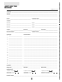
Just for the Record ____________________________________________________ 24
Programming Work Sheets ___________________________________ 25
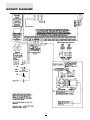
Hookup Diagrams ______________________________________________________ 36
Limited Warranty _______________________________________________________ 38
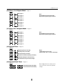
SPECIFICATIONS
Control Panel Specifications
Remote Keypad Specifications
(PC3000RK)
21 zones including:
•
•
•
•
16 fully programmable supervised zones (EOL resistors)
Supervised fire zone
1 auxiliary normally open zone
3 keypad activated zones
Audible alarm output:
• Four wire (QUAD) hook-up and up to 3 keypads per
system
• Built-in piezoelectric buzzer
• Full annunciation of zones and system status
• Nominal current draw 60 mA
• Dimensions 5.5" x 4.5" x 1" deep (140 x 114 x 25 mm)
• Bell output
700 mA, fused at 5 Amps, 11 VDC unregulated
• Steady or pulsed output
Output Voltage Specification
Due to the requirements of standards UL985 and UL1023, it
is required to indicate an output voltage of 11VDC
unregulated.
Typically, with normal AC in and a fully charged battery, the
output voltage will be 13.8 VDC. With AC off and a
discharged battery, the voltage will go to 10 volts. Devices
that require power from the control panel should be capable
of normal operation over the voltage range of 10 to 14 VDC.
EEPROM memory:
• Does not lose codes or system status on complete AC
and battery failure
Powerful 1.5 amp regulated power supply:
• 400 mA auxiliary supply, 11 VDC unregulated
• Separately fused for battery, keypad/auxiliary supply and
bell output
• Supervision for loss of AC power, low battery
• Internal clock locked to AC power frequency
Digital Communicator Specifications
• 92 reporting codes
• Transmits all 10BPS and 20BPS single line and extended
formats
• Radionics Rounds and Radionics Parity formats
• Sescoa Super fast format
• 3/1, 4/1, 4/2 and hexadecimal numbers
• DTMF and Pulse dialing
• DPDT line seizure
• True dial tone detection
• Anti-jam feature
• Two telephone numbers and two account codes
• Split reporting of selected transmissions to each telephone
number
Switched Smoke Detector Supply Output:
• Controlled from keypad [Q][4] command
Battery required:
• 12 volt 4 Ah minimum rechargeable gel-cell or sealed
lead-acid battery
Transformer required:
• 16.5 VAC, 40VA
Dimensions:
• 11" x 11.8" x 3.3" deep (279 x 300 x 84 mm)
Weight:
• 6.5 lbs (3 kg)
1
FEATURES
Keypad Programming
Advanced Features
The PC3000 comes with a default program so it is
operational with a minimum of programming. It is completely
programmable from the keypad. The panel uses EEPROM
memory so that all information is retained even if the panel
loses both AC and battery power.
The PC3000 has many advanced features. Features which
provide the security system design flexibility and selling
advantage necessary to win those demanding jobs and
make them profitable.
Some of these features include:
• EEPROM memory retains all data even on complete AC
and battery failure. Panel powers up in last armed or
disarmed state before power loss.
• All programmable zones may be selected as one of 11
different types including; delay, double delay, quadruple
delay, instant, interior, interior with home-away, delay with
home-away, and 4 types of 24 hour emergency and
supervisory circuits.
• Keypad programming of up to sixteen security codes.
• Zone bypassing from the keypad.
• Individual zone and system function indicators on keypad.
Although the PC3000 has many features, it is not difficult to
use. All keypad commands are similar and are assisted by
audible and visual cues.
Multiple Level Static/Lightning
Protection
The PC3000 has been carefully designed and tested to
provide reliable service. It is built to take static and lightning
induced surges and keep on working. Multiple level surge
filters are on all zone inputs, the power supply, the keypad
connections, the bell output, the auxiliary power supply and
the telephone interface. A special “ZAP-TRAC” circuit board
configuration catches high voltage impulses right at the
wiring terminals. Protective ground planes surround
sensitive areas preventing the spread of damaging voltage
surges. Metal Oxide Varistors (MOV’s) are placed in all the
critical areas to further reduce impulses to safe levels.
”WATCHDOG MONITOR” Circuit
Even when all precautions are taken so that voltage surges
do not cause damage to the control panel, it is possible to
cause temporary disruption to the operation of the
microprocessor causing it to lose track of the program
sequence. The PC3000 is equipped with an external
“Watchdog Monitor” circuit which continually checks the
microprocessor program execution.
System Supervision Features
The PC3000 continuously monitors a number of possible
trouble conditions including:
• An active battery supervision circuit that periodically tests
the battery under load.
• A loss of the AC power supply.
• A supervised fire circuit trouble condition.
• A telephone line monitoring circuit.
• A bell circuit failure indicates open circuit or fuse failure.
• A test code feature which transmits a communicator test
code to the monitoring station at a selected time everyday.
The test code can be sent at intervals from 1 to 99 days.
• A bell/siren/communicator test feature which can be
activated from the keypad.
• TLM (Telephone Line Monitoring) restoral transmission.
2
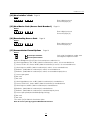
LONG RANGE RADIO
OPERATION
The PC3000 LRR Long Range Radio system features two modes of operation:
Mode 1:
Radio-Only Operation
Mode 2:
Radio with Land Line Communication
When programmed for Mode 1 operation, events
programmed to report to the First Telephone Number (see
“Call Direction Options” section [33]) will only be transmitted
through the LINKS2000 Long Range Radio connection.
When a LINKS2000 Long Range Radio transmission is to be
made, the LINKS2000 will be activated and three
transmissions will be made. There will be a 3-second delay
between each transmission. If additional events occur during
the transmission, additional transmissions will be made to
ensure that the last event is transmitted twice.
When programmed for Mode 2 operation, events to be
reported to the First Telephone Number will be
communicated through both the LINKS2000 and the normal
land line.
When an event is to be reported to the First Telephone
Number, the LINKS2000 will be activated and a transmission
will be made. Following the LINKS2000 transmission, the
control panel will call the land line number (programmed in
section [01]) and report the event again. If the land line
communication is successful, the control panel will hang up
the line and no further communication will take place.
If additional events occur during the land line
communication, the additional events will be reported over
the land line. After completing the land line call, the panel will
hang up and no further action is taken.
In either mode of operation, events programmed to report to
the Second Telephone Number are not communicated
through the LINKS2000 connection. This allows the system
to be programmed so that non-alarm events may be
reported over the land line without the use of the long range
radio connection.
Refer to Programming Section [19] 2nd System Option Code,
Zone Light 4, for instructions on selecting the LINKS2000
operating mode.
Note: If all reports are to be communicated through the
LINKS2000 and no phone line is connected to the
system, turn ON Zone Light 7 in section [19] to prevent
TLM troubles from being generated.
3
INSTALLATION
terminals, check the keypad connections and check the
panel fuses.
If all the zones are properly connected with end of line
resistors all of the zone lights will be off. Note that the panel
will arm only if all zones are properly connected with end of
line resistors (including FIRE circuit) so that the “Ready” light
is on. The keypad should beep several times to indicate
acceptance of the master code. Enter the Master Code to
arm or disarm the panel.
Read the “Keypad Commands” section of this manual or the
Instruction Manual and enter commands on the keypad to
become familiar with the different commands.
Turn to the “Programming Guide” in this manual and enter a
sample program into the panel through the keypad to
become familiar with the programming commands.
Bench Testing
The PC3000 contains a factory default program. Any
additional programming required can be done through the
keypad. For many applications all that will be required is to
enter the telephone number and alarm codes with keypad
entries that are as straight forward as dialing a telephone
number. If you need help talk to your DSC equipment
distributor.
Connect 1K ohm 1/2 watt end of line resistors from each
zone (Z1 to Z16) input to the closest common “COM”
terminal. Connect an end of line resistor between the “Fire”
input terminal and the “COM” terminal between “Z1” and
“Z2”. Unless all zone loops are properly terminated with end
of line resistors the “Ready” light will not be on and the
panel will not arm unless the “Ready” light is on.
Connect the 4 keypad wires to the control panel as shown in
the connection drawing.
For complete testing of the PC3000 LRR system, it is
suggested that both LINKS2000 and land line
communications be thoroughly tested. To test LINKS2000
communications, consult with the monitoring station to
determine their test procedures. To test land line
communications, connect the PC3000 to a digital receiver
through a telephone line connection or to a digital
communicator test set such as the DSC DTS-1.
The DSC DTS-1 digital communicator test set is an
inexpensive unit which can simulate the telephone system
dial tone and the receiver hand shake and kiss-off tones as
well as display the data sent out by a digital communicator.
Also, the DTS-1 has a “listen-in” feature which makes it ideal
for monitoring the transmission between communicator and
receiver when the PC3000 is connected to the telephone
line.
If you are using a DTS-1, connect the green and red
telephone clips to the “TIP” and “RING” terminals and
connect the red and black power clips to the “AUX [+]” and
“AUX [-]” terminals on the PC3000. When power is applied
to the panel press the red local-line button on the DTS-1 and
observe the display window area. The “local-line” indicator
should be in the local position.
For testing purposes, so that the sound level is not too loud,
connect a small buzzer to the “BELL [+]” and “BELL [-]”
terminals to indicate when the panel is in alarm.
Connect a 16.5 VAC, 40 VA transformer to the “AC”
terminals. Before plugging in the transformer be sure the
circuit board is not resting on anything metallic which may
cause a short.
Note: THE PC3000 WILL NOT START UP IF “AC” IS
OFF AND THE BATTERY IS LOW.
When the transformer is plugged in there should be lights
on the keypad and the buzzer connected to the bell
terminals may go on for a few seconds. The “Armed” light
may be on or off the first time the panel is powered. The last
armed/disarmed condition is stored in the EEPROM memory
so the panel will always power up in the last armed/
disarmed state. If the “Armed” light is on, enter the default
Master Code [1234] to disarm the panel. If the keypad is not
active, check for the presence of AC power at the “AC”
Mounting Panel
Select a dry location close to an unswitched AC source, a
ground connection and the telephone connection.
Remove printed circuit board, mounting hardware and
keypad from cardboard retainer inside panel. Before
attaching cabinet to wall, press the five white nylon printed
circuit board mounting studs and the ground connection
screw into cabinet from the back.
Pull all cables into cabinet and prepare them for connection
before mounting the circuit board to the back of the cabinet.
Press circuit board down onto mounting studs.
Hook-up Procedure
DO NOT connect transformer or battery until all other wiring
has been connected. See power-up procedure.
Connect a ground cable from the cabinet ground connection
by the shortest and most direct route to a grounding rod.
Connect zone cables to zone loop inputs and put end of line
resistors on any unused zones. Connect wires supplying
power for motion detectors to auxiliary supply.
Install keypads and connect wires to keypad terminals on
panel. Connect RJ31-X cord to telephone terminals. Do not
insert plug into RJ31-X jack.
Ensure that plugs and jacks meet the dimension,
tolerance and metallic plating requirements of 47 C. F. R.
Part 68, Subpart F.
WARNING: FCC restricts using this equipment on certain
types of telephone lines. Read FCC Compliance
Statement at the end of this manual. Also, do not use this
equipment on a telephone line equipped with ‘call
holding” feature because the tone generated may
interfere with the communicator operation.
Connect bell or siren to “BELL [+]” and “BELL [-]” terminals.
Observe correct polarity for sirens and polarized bells.
Connect 1K ohm 1/2 watt resistor across terminals to
eliminate trouble condition if bell circuit is not being used.
4
Terminal Connections
Auxiliary Input Terminal “AUX IN” (also KEY ARMING)
The “AUX IN” input terminal is a normally open 24 hour zone.
It can be programmed from the keypad to be silent or
audible. There is no display on the keypad for the “AUX IN”
input. An alarm on this input is created by applying a positive
voltage or by closing a contact between the “AUX IN”
terminal and the positive auxiliary supply. See “Programming
Guide [Q] [8]” sections [09] and [10] for programming the
alarm and restoral codes.
The “AUX IN” terminal can also be used as a momentary key
arming/disarming input. See “Programming Guide” section
[28] for a list of options for the “AUX IN” terminal.
Note: The keyswitch arming feature must be
implemented using a UL listed device.
“AC” Power Terminals
Use a 16.5 VAC transformer with a minimum 40 VA rating to
supply AC power to the PC3000. The transformer should not
be connected to an outlet that is controlled by a switch. If AC
failure occurs it is displayed as a trouble on the keypad (see
“Keypad Functions [Q][2] Trouble Conditions”). It can also
be transmitted to the monitoring station as a trouble
condition (see “Programming Guide [Q][8]” sections [09]
and [10] for alarm and restore codes and section [22] for AC
transmission delay).
Auxiliary Power Terminals “AUX” and “GND”
The auxiliary power supply can be used to power motion
detectors and other devices requiring 11 VDC. 400 mA 11
VDC is available from the “AUX” (positive) and “GND”
(negative) terminals when the PC3000 is used with one
keypad. For each additional keypad the auxiliary supply
rating must be reduced by 60 mA. The auxiliary supply is
fused with the keypad supply at 1 amp. Auxiliary fuse failure
transmission can be sent (see [Q][8] sections [09] and [10]).
”FIRE” Zone Input
The “FIRE” zone is a supervised (normally open alarm
initiating contact) end-of-line resistor circuit designed to
accept “Latching” four-wire smoke detectors.
(See “Fire Circuit Installation Diagram”.)
On alarm, (fire zone shorted) the bell output will pulse the
signal to indicate that the fire zone has been activated. Alarm
memory and transmission by the digital communicator is
delayed 30 seconds. If the alarm is acknowledged, by
pressing the [#] key before the 30 second delay has expired
the signals will silence and the transmission will be aborted.
If the alarm is not acknowledged and the 30 second delay
expires, the fire memory latches and the transmission cannot
be aborted.
If the smoke detector is not restored to normal after the
signal has silenced, the signal will resound after 90 seconds.
And 30 seconds after that, the communicator will transmit. If
the signals resound, they may again be silenced, [#] key,
and the communicator will be aborted if silence occurs within
the 30 second delay period.
To restore the smoke detector to normal, clear all products
of combustion from the detector and reset the detector by
pressing [Q] and then holding down [4] for 2 or 3 seconds.
This action will remove power from the smoke detector and if
it is clear of smoke, the detector will return to normal. If the
detector is still in alarm, the signals will sound immediately
and the above sequence will repeat.
For an open on the FIRE zone, the keypad sounder will beep
twice every 10 seconds and the “Trouble” light will show on
the keypad. The communicator will transmit the trouble
condition if programmed for trouble transmission. The
audible “Trouble” signal may be silenced by pressing the [#]
key. To determine the nature of the trouble, press [Q][2]. (see
the “Trouble Display” section.)
Switched Auxiliary Power Terminals
“SW AUX” and “GND”
The switched auxiliary supply can be switched off
momentarily from the keypad (see “Keypad Commands
[Q][4]”). The “SW AUX” terminal is positive and the “GND”
terminal negative. The 400 mA auxiliary supply rating must be
reduced by any current taken from the switched auxiliary
supply. The switched supply shares the same fuse as the
auxiliary supply.
Bell/Siren Terminals “BELL [+]” and “BELL [-]”
These terminals are for powering bells or other devices
requiring a steady output voltage on alarm. The bell output is
fused for 5 amps. When connecting sirens (speakers with
siren driver already built-in), be sure to observe the correct
polarity. Connect the positive lead to the “BELL [+]” terminal
and the negative lead to the “BELL [-]” terminal.
If no siren or bell is used, connect a 1000 ohm resistor
between “BELL [+]” to “BELL [-]”. The bell/siren alarm output
is pulsed (1 second on 1 second off) when an alarm is
created by the [F] keypad zone, by the FIRE zone, or when
the Bell Pulse option is enabled in section [19] light 1.
Note: During each LINKS2000 transmission the bell will
be turned off for approximately 1 second.
Keypad Terminals “RED”, “BLK”, “YEL” and “GRN”
Connect the four coloured wires from the keypads to these
terminals. When connecting more than one keypad, connect
in parallel across the keypad terminals at the control panel
(i.e. all reds wires together, all blacks together, all yellows
together and all greens together). The keypad red and black
power supply terminals are fused through the auxiliary fuse.
Zone Input Terminals “Z1” to “Z16”
Zone inputs “Z1” to “Z16” are supervised end of line (E.O.L.)
resistor circuits. Each input must be terminated with a 1K
ohm E.O.L. resistor. An alarm condition will be created if a
normally open contact is used to short across the E.O.L.
resistor. An alarm is also created if normally closed contacts,
wired in series with the E.O.L. resistor, are opened. See the
wiring diagram for normally open and normally closed
contact connection. The type of circuit or zone definition
Programmable Output Terminal “PGM OUT”
Connect the PC3000 PGM OUT terminal to the “PGM”
terminal on the LINKS2000. When the LINKS2000 unit is
used with the PC3000, the PGM output may not be used for
any function other than the LINKS2000.
5
that the panel and keypad are responding to signals. If the
keypad does not respond and there are no indicators on,
check for AC voltage at the “AC” terminals. If there is 16 VAC
present, check that the keypad wiring is correct and check
the keypad/auxiliary supply fuse. If the keypad/auxiliary
supply fuse is blown check for a short between the keypad
red and black wires before replacing the fuse.
If the keypad is responding normally, connect the battery.
The red battery lead attaches to the positive battery post and
the black battery lead attaches to the negative battery post.
Note : THE PC3000 WILL NOT START UP IF ‘AC’ IS OFF
AND THE BATTERY IS LOW.
(delay, instant, 24 hour etc.) is programmed from the keypad
using the [Q][8] Installer’s Programming commands
("Programming Guide" sections [16] and [17]).
NOTE: For UL installations, zone inputs must be
terminated with normally closed initiating devices or endof-line resistors (1K ohm).
Telephone Terminals “TIP”, “RNG”, “T-1” and “R-1”
The wires from the RJ31-X telephone jack are connected to
these terminals in the following way.
TIP
RNG
Green wire
Red wire
Incoming line from
telephone company
T-1
R-1
Brown wire
Grey wire
Outgoing line to
house telephone(s)
Testing The System
It is recommended that both land line and LINKS2000
communications be thoroughly tested when installation is
completed. To test both communication systems, program
the control panel for Mode 2 operation so that
communications will be made over both the land line and the
LINKS2000.
Connect the LINKS2000 and plug the telephone cord in the
RJ31-X jack. If desired, a DTS-1 may be used to monitor the
land line communications; connect the DST-1 as described
in the “Bench Testing” section of this manual. Place the DTS1 into “line” mode to monitor the land line communications.
Note: For proper operation there must be no other
telephone equipment connected between the control
panel and the telephone company's facilities.
Do not connect the alarm panel communicator to
telephone lines intended for use with facsimile (FAX)
machines. These lines may incorporate a voice filter
which disconnects the line if other than FAX signals are
detected, resulting in incomplete transmissions.
Ensure that plugs and jacks meet the dimension,
tolerance and metallic plating requirements of 47 C. F. R.
Part 68, Subpart F.
Perform an Installer’s Test by entering [Q][6][Master
Code][0]; refer to the “Keypad Functions” section of this
manual for instructions on using the Installer’s Test
command.
The system may also be tested by arming the system and
then activating instant zones after the Exit Delay has expired.
After a zone has been activated, wait for all communication
to be completed and then disarm the system. Check with the
monitoring station to ensure that both the land line and
LINKS2000 communications were completed successfully.
Perform additional transmissions as required by the
monitoring station.
Battery Connections
Do not connect the battery or the transformer until the wiring
is complete. Connect the red battery lead to the positive
battery terminal and the black lead to the negative battery
terminal. If the connection is made in the reverse the battery
fuse will fail. If the battery charging voltage is out of
adjustment, contact your service representative.
Note: The battery charging voltage must not be adjusted
on UL Listed systems.
Check the “Trouble” light on the keypad. If it is on, press [Q]
then [2] to determine if there is a system trouble. The
“Trouble Display” section in “Keypad Commands” gives a
description of the different trouble conditions.
Keypad Installation
Mount the keypads near the exit-entry doors. The PC3000RK
keypad has a red, a black, a green and a yellow wire on the
back. Connect these four wires to the four keypad terminals
on the control panel using four conductor (quad) telephone
wire. Up to three keypads may be connected to one
PC3000. Connect all green wires from the keypads to the
“GRN” terminal on the panel. Connect all yellow wires from
the keypads to the “YEL” terminal on the panel. Connect all
red wires from the keypads to the “RED” terminal. Connect
all black wires from the keypads to the “BLK” terminal.
Instructing End-User
Fill out the system reference guide in the PC3000 Instruction
Manual. Check off sections in the manual which apply to the
user’s system and make additional notes if necessary.
Describe the system to an authorized user. Describe arming
and disarming procedures. Describe the basic keypad
functions. Assist the user in working through examples of
each type of command.
Provide user with the Instruction Manual and instruct them to
read the manual to become familiar with the system
operation.
Instruct the user to test the system on a regular basis as
described in the Instruction Manual. The Master Code
should be changed from the default setting and recorded in
the Instruction Manual.
Power-up Procedure
If the keypads are located a distance from the panel, install
an extra keypad temporarily at the panel during power up
testing. An extra keypad with a short length of cable and
alligator clips attached is helpful for testing and
programming PC3000 systems.
Connect the transformer, wait approx. 5 seconds.
Enter a few keypad commands and open a zone to be sure
6
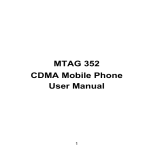
GUIDELINES FOR SMOKE
DETECTOR LOCATION
Experience has shown that all hostile fires in family living
units generate smoke to a greater or lesser extent.
Experiments using typical fires in family living units indicate
that detectable quantities of smoke precede detectable
levels of heat in most cases. For these reasons, NFPA
standard 74 requires smoke detectors should be installed
outside of each sleeping area and on each additional story
of the family unit.
Bedroom
The following information is for general guidance only and it
is recommended that the smoke detector manufacturer's
literature be used for detailed installation instructions.
Bedroom
Living
Room
It is recommended that additional smoke detectors beyond
those required be installed for increased protection. The
added areas include: basement, bedrooms, dining rooms,
furnace room, utility room and hallways not protected by the
required detectors.
Bedroom
Hall
Dining
Room
Basement
Bedroom
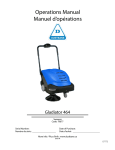
FIG. 3: A smoke detector should be located on each
story of the living unit.
Bedroom
Ceiling
4 in.
(0.1m)
Bathroom
Acceptable here
Living
Room
Kitchen
4 in.
(0.1m)
minimum
Never here
12 in.
(0.3m)
maximum
Top of detector
acceptable here
FIG. 1: A smoke detector should be located between
the sleeping area and the rest of the family unit.
Note:
Measurements shown are to the
closest edge of the detector.
Bedroom
Side wall
Dining
Room
Kitchen
Living
Room
Family
Room
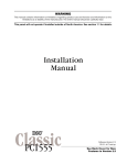
FIG. 4: Smoke Detector mounting - “Dead” Air Space.
The smoke from a fire generally rises to the ceiling,
spreads out across the ceiling surface and begins to
bank down from the ceiling. The corner where the
ceiling and wall meet is an air space into which the
smoke may have difficulty penetrating. In most fires,
this “dead” air space measures about 4 in. (0.1m) along
the ceiling from the corner and about 4 in. (0.1m) down
the wall as shown in Figure 4. Detectors should not be
placed in the dead air space.
Bedroom
Bedroom
FIG. 2: In the family living units with more than one
sleeping area, a smoke detector should be located to
protect each sleeping area.
7
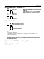
KEYPAD FUNCTIONS
Introduction
Disarming
The PC3000RK remote keypad provides complete
information and control of the PC3000 control panel. The
panel can be fully programmed from the keypad. The 16
zone lights and the fire alarm light provide alarm and status
indication for the alarm circuits. The 6 function lights guide
the user in operating the system. The built-in buzzer lets the
user hear correct key entries and other alert signals. The 12key keypad is used for code entry and other programming
functions. All keypad entries are made by pressing one key
at a time.
The keypad is normally resting in the arm-disarm mode. In
this condition the zone lights are indicating the opening and
closing of zones. The “Ready” light comes on when all zones
are closed. The system can be directed to perform other
functions such as zone bypassing, displaying trouble
conditions, displaying alarm memory and programming by
entering one of the various [Q] commands described below.
Pressing the [#] key or not making any key entry for 2
minutes always returns the keypad to the arm-disarm mode.
Enter the premises through the designated exit-entry door.
The keypad buzzer will be on. Go to the keypad and enter
the [4 digit security code]. If an error is made in entering the
code, press the [#] key and enter the code again. The
“Armed” light will go out and the keypad sounder will stop.
The correct security code must be entered before the
allowed entry time expires. To change the entry time see
“Installer’s Programming Command”, [Q][8]. If an alarm
occurred while the panel was armed, the “Memory” light and
the “Zone” light which caused the alarm will start to flash and
stay flashing for 2 minutes when the panel is disarmed.
Pressing the [#] key returns the panel to the normal armdisarm mode.
Auto-bypass/Home-Away Arming
If a correct security code is entered, and you do not exit the
premises, the system will, at the end of the Exit delay time,
arm with interior zones automatically bypassed if those
interior zones have been programmed as “Home-Away”
zones. The “Bypass” light will come on immediately following
the arming code being entered until a delay zone is tripped
or [Q] [1] is entered to reactivate bypassed home-away
zones. (See programming sections [16] and [17], zone
definitions for programming zones as “Home-Away”.)
This is a convenience feature for the user who wishes to
remain at home with the system armed. The user does not
have to manually bypass the home-away zones.
To reactivate the home-away zones that have been
automatically bypassed, press [Q] [1]. The “Bypass” light will
go out. This command is a quick method of fully arming the
system before going to bed.
Master Code
A default Master Security Code “1234” is programmed into
the PC3000 at the factory. The Master Security Code is used
for arming and disarming the control panel, for programming
up to fifteen additional security codes using the [Q][5]
command and for entering other user functions using the
[Q][6] command. The Master Code can be reprogrammed if
the installer leaves section [19] light 2 off. Because the
PC3000 uses EEPROM memory the codes and other data
are retained even after complete AC and battery failure.
Installer’s Programming Code
A default Installer’s Programming Code “3000” is
programmed into the PC3000. This code is used with the
[Q][8] command by the installer to gain access to the system
in order to enter panel or communicator program information.
The Installer’s Programming Code may be changed by the
installer.
Zone Bypassing
A bypassed zone will not cause an alarm. If a zone is
bypassed the panel may be armed (“Ready” light will be on)
even if the zone is open. Use zone bypassing when access
is needed to part of the protected area. Also, damaged
wiring or contacts on a zone may be temporarily bypassed
until repairs can be made so that the panel can be armed.
Arming
Check to see if the “Trouble” or “Bypass” light is on before
arming the PC3000. Close all protected doors and windows
and stop movement in areas covered by motion detectors.
Check to see that the “Ready” light is on (all zones are
closed). The system cannot be armed unless the “Ready”
light is on. Enter a [4 Digit Security Code]. As each digit is
entered the keypad buzzer will beep. If the security code
was entered incorrectly, the sounder will beep steadily for 2
seconds. If the code was entered correctly but the “Ready”
light was not on, the keypad will beep quickly followed by a
steady tone. When the correct code is entered, the “Armed”
light will come on and the keypad buzzer will beep quickly.
Exit the premises through the designated exit-entry door. At
the end of the allowed exit time all lights on the keypad will
go out except the “Armed” light. See the “Installer’s
Programming [Q][8] Command” section [22] for instructions
on how to change the exit time. Also see, “Quick Arm” and
“At Home Arming”.
[Q]+[1]
To bypass zones, enter [Q] [1] and the zone number(s) to be
bypassed. Press [#] to return to “Ready” (arm-disarm
mode). When bypassing zones, two digits must be entered
for the zone number(s) to be bypassed (e.g. [Q] [1]
[01]....[16]). To remove all bypasses, enter [Q] [1] [00] [#].
The “Zone” lights which are on, while the “Bypass” light is
flashing, indicate the bypassed zones. Remember that if no
keypad entry is made for more than 2 minutes the keypad
will return to the arm-disarm mode. Then, in order to bypass
a zone the complete command must be re-entered. Once
the bypass command is entered, pressing [99] recalls the
last zone or group of zones which was bypassed. If the
same group of zones is bypassed each time, this bypass
recall feature can be used instead of having to bypass zones
individually.
8
When the PC3000 is programmed, the ability to bypass
certain zones may be eliminated. In this case, the “Zone”
lights for those zones will not come on in response to the
bypass command. See the “Zone Bypass Mask” instruction
in the [Q][8] Installer’s programming section. If the “Bypass”
light is on when arming the panel, the [Q][1] command
should be used to see which zones are bypassed so that
zones are not unintentionally bypassed. Zone bypasses are
automatically cancelled when the panel is disarmed.
4 Telephone Line Trouble...A telephone line trouble is
generated when the line voltage drops below 3 volts for more
than 60 seconds. It generates a keypad trouble when the
system is disarmed and rings a local alarm when the panel is
armed if section [19] light 5 is off.
5 Unsuccessful Communication...If the digital
communicator is unsuccessful communicating with the
monitoring station after eight attempts, a trouble is
generated.
If a later attempt to communicate is successful the trouble is
cleared.
[Q] + [1] + [Access Code]
If light 8 in section [19] is on then a code must be entered
with [Q]+[1] to bypass zones. Only the zones assigned to
the same side of the system as the user code can be
bypassed. The ability to bypass using certain access codes
can be eliminated. See the “Access Bypass Mask”
instruction in the [Q] [8] Installer’s Programming section.
6 Bell Circuit Failure...If the bell fuse fails or the bell circuit
is open, a keypad trouble and a trouble transmission are
generated.
7 Smoke Detector Zone Trouble...If a Fire zone is open
circuit, a keypad trouble and a trouble transmission are
generated. A trouble on the Fire zone will unconditionally
initiate an audible indication on the keypad. This means that
even if any other previous trouble has been silenced, a Fire
zone trouble will restart the keypad buzzer.
Note: At no time can any armed zone be bypassed.
Trouble Display
[Q]+[2]
The PC3000 continuously monitors a number of possible
trouble conditions. If one of these conditions occurs, the
keypad “Trouble” indicator will light and the audible
indication will sound (two short beeps every 10 seconds).
When the [#] key is pressed the audible indication will stop
but the “Trouble” indicator light will remain on until the
trouble is cleared. Trouble conditions can also be
transmitted to the monitoring station (see “Programming
Guide” sections [09] and [10] for alarm and restoral trouble
codes). Press the [Q] then [2] keys to display the type of
trouble. The “Zone” lights indicate the type of trouble
condition.
1 Low stand-by battery
2 AC power failure
3 Day zone trouble
4 Telephone line trouble
5 Uncessful communication attempt with monitoring station
6 Bell circuit failure
7 Smoke detector zone trouble
8 Loss of time on internal clock
Press [#] to return to “Ready”.
8 Loss of Internal Time...When the PC3000 is powered up
or reset, the internal clock needs to be set to the correct
time, day, month and year. This trouble is cleared when the
trouble display is viewed and exited or when an attempt is
made to reset the internal time of day clock. See “[Q][6]
User’s Function Command” for resetting time of day clock.
If the [9] is pressed while in the trouble display mode the
most recent trouble will be displayed on the zone LEDs. This
trouble memory feature is useful as a diagnostic aid when
installing and servicing the PC3000.
Alarm Memory Display
[Q]+[3]
Press [Q] then [3] to enter the alarm memory mode. The
“Memory” light will flash and any alarm caused during the
last armed period will be displayed on the zone lights. In
addition to the last alarm memory there is 1 history level.
After entering the memory mode (pressing [Q] then [3]),
pressing [9] will cause the keypad to display the other level
of alarm history. Each time [9] is pressed the keypad will
beep 1 or 2 times to indicate which level of history is being
viewed. When the panel is armed, the last alarm memory is
cleared and the contents moves to the 1st history level. The
“Memory” light will only be on when there was an alarm
during the last armed period.
Press [#] to return to “Ready”.
1 Low Battery...A battery trouble will be displayed and can
be reported if the battery is weak, disconnected or the
battery fuse is blown. Only one low battery alarm or restoral
transmission takes place per arming period. Low battery
trouble display is latching and can only be cleared by
battery restoration, arming and disarming panel.
Switched Auxiliary Supply Control
2 AC Power Failure...There is no audible annunciation on
AC power failure. The system “Trouble” light will come on but
the audible indication will not sound until there is a low
battery condition. Transmission delay can be programmed
for 1 to 99 minutes. See “Programming Guide” section [22].
[Q]+[Hold Down 4]
To interrupt the switched auxiliary power supply press [Q]
then hold down [4] for the desired interrupt time. When the
[4] is released the system returns to the “Ready” mode and
the switched auxiliary supply is restored.
3 Day Zone Trouble...This trouble applies only to zones
which have been programmed as day zones. (“Programming
Guide” sections 16 and 17). A day zone creates a trouble
signal when the panel is disarmed and an alarm signal when
the panel is armed.
9
User’s Programming Commands
[Q]+[5]+[MASTER CODE]
The [Q][5] user’s programming command is used to
program additional access codes. Up to 16 user arm-disarm
codes may be programmed. The 1st code is the Master
Code (factory default [1234]). The 16th code is optionally a
“One Time Use” or maid code. The 16th code may be
changed from a “One Time Use” code to a regular code
using an installer’s programming command (section [18]...1st
system option code). Remember if no keypad entry is made
for more than 2 minutes the keypad will return to the normal
arm-disarm display and the complete command will have to
be re-entered to program a new access code.
Programming Additional Access Codes
1 Press the [Q] and [5] keys then enter the Master Security
Code (default [1234]) to enter the additional code
programming mode. The “Program” light and “Zone 1” light
will be on to show that the first code (the Master Code) is
already programmed with the factory default code [1234].
The Master Code may be changed but do not try to erase
the Master Code. The installer can disable user changing of
the Master Code by turning on light 2 in section [19].
2 15 additional codes may be programmed. The zone lights
are used to indicate which of these codes are already
programmed (zone light on steady) and the one which is
currently being programmed (zone light is flashing).
3 To program the second code, press [02] then enter a 4
digit code. Zone 2 light will flash and sounder will beep three
times and zone light 2 will come on steady after the 4 digit
code is entered.
4 To remove the second code, press [02] - the buzzer will
beep three times and zone light 2 will flash. Enter [Q] [Q] [Q]
[Q], the buzzer will beep three times and zone 2 light will go
out to show that the code has been removed.
5 Follow the instructions in 3 or 4 for programming or
removing any of the other additional codes.
6 Do not try to remove the Master Code (1st code). The
Master Code may be changed but it must not be removed.
When changing the Master Code be sure to enter a valid 4
digit number (use only number keys 0 to 9). Do not enter [#]
or [Q] as one of the digits. If the Master Code is forgotten
and the panel is left disarmed, program a new Master Code
using the [Q][8][Installer’s Code][25] command. If the Master
Code is forgotten and the panel is left armed, the entire
programming can be reset to factory default by using the
“Hardware Reset” method described on page 21.
7 To successfully program or remove additional codes, the
panel must be put into the code program mode by following
step 1 followed by steps 3 or 4. Note that if no key entry is
made for 2 minutes the panel will go back to the normal
arm/disarm mode, after which step 1 must be repeated to
get back into the code program mode.
8 To exit the code program mode press [#].
10
To review:
programming a new code;
enter [Q] [5] [Master Code] [01 to 16] [4 digit code]
eliminating an existing code;
enter [Q] [5] [Master Code] [02 to 16] [Q Q Q Q].
Note: The access code, numbers must be entered as
two digits. E.g. 02, 03,......, 15, 16.
User’s Functions Command
[Q]+[6]+[MASTER CODE]
This command is used to set the system clock time and to
set the Auto-arm time. It is also used to turn on and off a
number of system functions. The command is used by
entering [Q], [6], [Master Code] then a number from the
following list to select the item to be changed.
[0] Installer’s test
[1] System 24 hour clock (enter HH:MM, Day, Month, Year)
[2] Auto-arming time (enter HH:MM)
[3] DO NOT USE
[4] Quick arm enable/disable
[5] Auto-arm enable/disable
[6] Door chime enable/disable
[7] DO NOT USE
[8] Bell test function
[9] User Initiated Callup
Note: The system clock is a 24 hour clock and times
must be entered as two digit number.
e.g. HH - 00, 01,.....10, 11,.....22, 23
MM - 00, 01,.....35, 36.....58, 59
[1] and [2] are time setting functions.
For option [1], enter 4 digits representing the time in hours
and minutes (HH:MM) based on the 24 hour or military clock.
Then enter 2 digits each for the day 01...31, the month
01...12, and the year xx. Always enter a leading zero where
only 1 digit is required, i.e. 8:05 am would be entered as
0805 and 1:30 pm would be entered as 1330.
Option [2] requires a 4 digit entry defining the auto-arming
time in hours and minutes (same procedure as item [1]).
[0], [4], [5] and [6] turn on and off various features. When the
option key is pressed, the feature is turned on if the keypad
beeps quickly 3 times. The feature is turned off if the keypad
sounds one long beep.
[8] gives a 2 second bell and keypad light test.
[9] makes the panel call the Downloading computer if
enabled in section [47].
Installer’s Test
[Q]+[6]+[MASTER CODE]+[0]
This feature is designed to assist the installer in testing the
system. In this mode, the bell or siren will operate for two
seconds each time a device is tripped and the zone alarm
will be put into the first level memory. The feature is
automatically disabled when the panel is armed and
disarmed. Each time a zone is tripped or restored in this
mode, a signal, if programmed, will be transmitted to the
monitoring station. If this is not desired, it is possible to
disable the communicator during the test (see section [18]
“1st System Option Code”).
Note: Do not use the installer’s test when the panel is
partially armed.
Quick Arm
[Q]+[6]+[MASTER CODE]+[4]
The “Quick Arm” feature is enabled by pressing the [4] key
while in the “User Functions Command” section. When
enabled (enabled 3 beeps....disabled one long beep) the
panel can be armed by entering [Q][0]. The closing code
transmitted for “Quick Arm” is the same as the code which is
programmed for the Master Code.
Auto-arm Enable
[Q]+[6]+[MASTER CODE]+[5]
Entering [Q] [6] [Master Code] [5] will enable/disable the
Auto-arming feature. When the feature is being Enabled, the
keypad buzzer will sound 3 beeps and when being Disabled
the buzzer will sound one long beep.
Setting the Clock
[Q]+[6]+[MASTER CODE]+[1]
Setting the “System 24 Hour Clock” (item [1]) tells the system
the correct time of day. If the system is without battery and
AC power it cannot continue to keep time. Therefore when
the panel is first powered up or when it has been without AC
power long enough to completely discharge the stand-by
battery, the “System 24 Hour Clock” must be reset.
Door Chime
Auto-arm Time of Day
[Q]+[6]+[MASTER CODE]+[2]
The PC3000 can be programmed to arm at the same time
each day. Programming item [2] sets this time and the
feature must be enabled as shown in item [5] (see “Auto-arm
Enable” on this page).
At the selected auto-arm time the keypad beeper begins to
sound and the Bell/Siren will pulse once every 10 seconds to
alert anyone on the premises that the system is about to arm.
The Bell/Siren pulse can be silenced in section [51] by
turning light 1 on.
The keypad beeper will sound for one minute before autoarming unless one of the following two methods is used to
cancel the auto-arm.
• Auto-arm Abort: Any key can be pressed to abort the
auto-arm sequence and silence the keypad during the one
minute pre-alert (this is the default condition).
• Auto-arm Abort with Code: If section [51] light 2 is on,
then a valid 4 digit access code is required to abort the
auto-arm sequence.
The auto-arm will be attempted at the same time the
following day. Any time an auto-arm is aborted using one of
the above methods, the reporting code programmed in
section [45] will be transmitted to the central station.
[Q]+[6]+[MASTER CODE]+[6]
The “Door Chime” feature is enabled by pressing the [6] key
while in the “User’s Functions Command” section. When
enabled the keypad buzzer will beep quickly 5 times each
time any zone defined as a delay or instant circuit opens or
closes. The “Door Chime” feature does not operate on other
zone definitions. Zone bypass may be used to eliminate
“beeping” on doors where it is not wanted. This feature
operates only while the panel is disarmed.
System Test
[Q]+[6]+[MASTER CODE]+[8]
Entering the System Test command will sound the bell/siren,
turn ON the keypad lights and sound the keypad buzzer for
2 seconds.
If a System Test Code is programmed in section [45], it will
be transmitted to the monitoring station using the land line
connection.
If a System Test Code is programmed in section [45], the
LINKS2000 will also be activated and “8F” - a nonprogrammable test code used only by the LINKS2000 - will
be transmitted to the monitoring station.
User Callup
[Q]+[6]+[MASTER CODE]+[9]
This function is enabled in section [47]. When activated, the
panel will call the downloading computer. The downloading
computer must be waiting for the panel to call before
downloading can be performed.
11
Installer’s Programming Commands
Keypad Zones
[Q]+[8]+[INSTALLER’S CODE]
The PC3000 is completely programmed from the keypad by
using commands in the [Q] [8] section. The commands are
described in detail in the programming section of this
manual.
There are three zones which can be activated from the
keypad. The alarm and restoral codes for keypad zones are
programmed using the [Q][8] command.
Pressing the [F] key for 2 seconds activates a Fire alarm.
The fire alarm sounds the siren/bell in a pulsed mode and is
annunciated as a memory condition.
Pressing the [A] key for 2 seconds activates an Auxiliary
keypad zone. If a reporting attempt is made to an alarm
receiver and it is successful the PC3000 will acknowledge
the transmission with a short series of beeps from the
keypad.
Pressing the [P] key for 2 seconds activates the Police (or
Panic) alarm. The panic alarm can be programmed for
audible or silent operation (see section [18] in “Programming
Guide”).
There is no light annunciation from the keypad for the last
two keypad zones, however, the keypad buzzer beeps 3
times to confirm activation on any of the keypad zones. If the
keys are held down the buzzer continues to beep. The panic
alarm can be programmed for silent confirmation in section
[51] light 4.
See section [15] for alarm and restoral codes for all three
keypad zones.
“At Home” Arming
[Q]+[9]+[ACCESS CODE]
Entering [Q], [9] before the arming code, arms the panel
without any entry delay on the delay zones and bypasses
zones that are defined as “Home-Away”. This command is
used for arming the system while at home. When the panel is
armed using [Q], [9], the “Armed” light will be on flashing
and the “Bypass” light will be on to indicate that the “HomeAway” zones are bypassed. Once the panel is armed in this
mode, using [Q], [1] will remove the bypass from those
zones defined as “Home-Away” if they have NOT been
manually bypassed. The [Q], [1] command used here, only
removes the bypass from zones that have been
Automatically bypassed with the [Q], [9] command.”
“Quick Arm” Command
[Q]+[0]
Entering [Q][0] is accepted as a valid arming code when
the “Quick Arm” feature is activated. Quick Arm may be
used as a convenience for regular users or when the
system is to be armed by individuals who are not
authorized to disarm the system. See instructions in the
“[Q][6] User’s Functions Command” section for activating
the “Quick Arm” feature. This feature should not be
enabled if the One Time Use Code is enabled. The One
Time Use Code must be used for arming before it is
erased.
Quick Exit
[Q]+[0] When Armed
Entering [Q] [0] when the system is fully armed will allow the
user 2 minutes to exit the premises through any delay zone
without altering the status of the system if the Quick Exit
feature is enabled. The Quick Exit feature can be enabled by
turning on light 6 in section [51]. After [Q] [0] is entered into
an armed system, one and only one delay zone may be
tripped. Any additional activity on any other active zone will
cause that zone to begin its alarm sequence.
[Q] [0] for Quick Exit on a partially armed system is not
supported.
12
DOWNLOADING
The PC3000 with version 7.0 or higher software, supports the
DSC “downloading” package. See the downloading manual
for details on specific capabilities.
There are several sections pertaining to the downloading
feature which must be programmed.
Downloading and Answering Machine
The PC3000 software provides a means to handle
downloading when an answering machine is also connected
to the telephone line. In section [47], if zone light 7 is off, it is
assumed that there is no answering machine connected to
the telephone line and the panel will capture the line after the
set number of rings.
If zone light 7 is off and an answering machine is connected
and it is set to answer before the panel, the panel will be
unable to receive a call from a downloading computer. If the
panel is set to answer before the answering machine, the
answering machine will be unable to receive incoming
messages.
If zone light 7 is on and the panel is called for 1 or 2 rings
only and then called again within a set time of 60 or 120
seconds (set in section 51, light 7), the panel will then
answer the second call on the first ring (Answering Machine
Over-ride Timer).
Once the panel is connected to a downloading computer, no
[Q] functions can be performed. If the [Q] key is pressed
while the panel is connected to a downloading computer, the
keypad buzzer will sound one long tone to indicate an error.
Section [23]
The time of day that the periodic download or test
transmission will be done, if selected, is programmed in this
section.
Section [26] - Downloading Access Code
A four digit code must be programmed into this section to
allow access to the control panel by the downloading
computer.
Section [46] - Downloading Computer Telephone Number
If Callback is enabled, section [47] zone light [8], then this
section must be programmed with the telephone number of
the downloading computer.
Section [47] - Modem Configuration
Zone light [8] is programmed to enable or disable
callback. If callback is disabled, the downloading
computer will have immediate access to the control panel.
The disabled mode is useful if there are multiple
downloading computers (at different telephone numbers). If
callback is enabled the downloading computer will call,
request access then hang up and wait for the control panel
to call. After the control panel has called back and the
downloading computer and the control panel accept each
other as valid, downloading operations are enabled.
Zone lights [1] to [4] are programmed to set the number of
rings the panel will look for before it answers a call from the
downloading computer.
Zone light [5] is programmed to enable or disable the
control panel for downloading. If downloading is disabled, all
other programming sections relating to downloading need
not be programmed.
Zone light [6] enables or disables user initiated callup to the
downloading computer.
Section [48] - Panel Identification Code
A 4 digit code must be programmed into this section to
allow the downloading computer to identify the panel it is
communicating with.
Zone light [7] enables or disables the answering machine
defeat option (Answering Machine Over-ride).
Section [49] - Periodic Function Enable/Disable
Zone light [8] is programmed to choose between periodic
download (light ON) or test transmission (light OFF).
Section [51] - 3rd System Option Code
Zone light [7] sets the Answering Machine Over-ride Timer
to either 60 or 120 seconds for defeating the answering
machine.
See “Downloading and Answering Machine” section above.
13
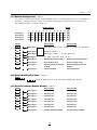
PROGRAMMING
GUIDE
“HEX” numbering the letters A...F represent the numbers
10...15). Where commands require “HEX” data A-F, first
press [Q]. The keys 1-6 now assume the hex values A-F and
the “Ready” light begins to flash. Key 1 = A, Key 2 = B, Key
3 = C, Key
4 = D, Key 5 = E and Key 6 = F. Pressing the [Q] again stops
the “Ready” light from flashing and the keys assume the
normal values for the numbers from 1 to 9. The most
common mistake in entering “HEX” data is forgetting to press
[Q] again after entering the “HEX” digit to return to normal
number entry.
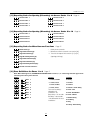
The data for sections 18, 19, 20, 21, 29, 30, 31, 32, 43, 44,
47, 49 and 51 is entered using the keypad zone lights to
indicate which functions are active and the number keys to
turn functions on and off. When the section number is
entered, the zone lights 1...8 will display which functions are
currently on. Pressing the number key corresponding to the
zone light alternately turns the function on and off. All
functions can be turned off by entering [0]. When the correct
selections have been made press [#] to record them in
memory and to go on to program the next section.
Introduction
The PC3000 is programmed by entering instructions from the
panel keypad. The PC3000 memory is EEPROM and can be
reprogrammed thousands of times. The EEPROM will not
lose memory even on total AC and battery failure. All
essential program information required to define the
operation of the control panel and the communicator is
stored in a section of the EEPROM which can only be
accessed using the Installer’s Programming Code. If the
code is forgotten, the default program code can be reinserted by using the “Hardware Reset” described on page
21, unless Installer’s Lockout is enabled. See sections [90]
and [91].
To begin programming the PC3000, enter [Q], [8], [3000]
while the panel is disarmed. Installer’s Programming can
only be done while the panel is disarmed and not in alarm.
The factory default Installer’s Programming Code is [3000].
This default code can be changed using the Section [24]
command listed below (new Installer’s Code). Once the
basic Installer’s command is entered ([Q] [8] [3000]) the
“Program” light will start to flash. The “Program” light will
continue to flash while programming. Note that while
programming, if no key entry is made for more than 2
minutes, the keypad will return to the arm-disarm mode and
the complete installer’s command ([Q] [8] [3000]) must be
entered before programming can resume.
The next step is to enter a 2 digit section entry for any of the
commands described in the following pages. Note that while
the keypad is waiting for the section entry the “Armed” light
is on steady. As soon as the 2 digits are entered for the
section the keypad will beep 3 times, the “Armed” light will
go out and the “Ready” light will go on. The keypad is then
ready to accept data entry for the selected section.
A complete description of each programming section will be
given in the remaining pages of this section. A programming
work sheet summarizing all programming commands is
provided in the next section of the manual. Fill out the work
sheet and use it as a guide when programming.
As the required data for a programming section is entered,
the hexadecimal value of the information in that location is
displayed on zone lights 1-15. Most sections contain several
groups of two digit entries. The keypad beeps twice and the
“Armed” light flashes after each group of two digits is
entered. When the required data is completely entered for
the section being programmed, the keypad will beep 5 times
and the “Armed” light will come back on to indicate that the
expected data has been entered and another section can be
selected for programming. After completing one section, it is
not necessary to re-enter the [Q] [8] [Installers’ code] portion
of the command. Just enter the number of another
programming section. When programming a section, it is
possible to exit by pressing [#]. Only the data entered before
pressing [#] will be changed in the EEPROM. Practice
entering data in several sections until you become familiar
with the programming commands.
Certain programming entries may require “HEX” data. That is
the numbers 0 through 9 and the letters A through F (in
Reviewing Programmed Data
Enter the section you wish to review by entering the 2 digit
section number. The zone LED’s will represent the value
(hexadecimal format) of the first digit in that section. Each
press of the ‘F’ key will advance the display to the next digit.
At the end of the section, the keypad buzzer will beep
several times and return you to the program mode where
another section can be selected for review or programming.
Note: Only sections [01] through [17], [22] through [28],
[33], [45], [46], [48], and [52] through [53] can be
reviewed using the above method.
[00] Binary Programming
This section is normally used upon instruction from factory
technical personnel for specialized programming not
covered by the standard programming instructions.
[01] 1st Phone Number
For land line communications, this is the first telephone to
which the communicator will dial (see section [33] “Call
Direction Options”).
After entering the section number [01], enter the
communicator telephone number the way you would dial it
on a telephone. Press [#] after the last digit to complete the
telephone number programming.
Enter [ Q 2 Q ] to dial a ‘Q’ (Hex B)
Enter [ Q 3 Q ] for a 4 second pause (Hex C)
Enter [ Q 4 Q ] for additional dial tone search (Hex D)
Enter [ Q 5 Q ] to dial a ‘#’ (Hex E)
The total number of digits including dial tone searches and
pauses must not exceed 16. Remember to press [#] after
entering the last digit of the phone number. Press [02] to
program the next section, enter another section number or
14
two digit numbers to be entered as the reporting codes for
zones 1 to 8 alarms (restorals in Section [07]). These codes
are used by the communicator when there has been an
alarm on zones 1 to 8. Listed below are several
programming examples and the resulting transmission using
different formats for the reporting codes. Obtaining different
formats requires entering data correctly in the account code
section ([02] or [04]) reporting codes sections ([05] to [15])
and communication format options, section ([27]).
press [#] a second time to return to the arm/disarm mode.
[02] 1st Account Code
The 1st Account Code is always transmitted to the 1st Phone
Number to identify the client.
After entering the section number [02], enter a 4 digit
number. If “HEX” digits A to F are required; enter [Q], [1]...[6]
and [Q] again to return keys to normal decimal entry. Where
a zero digit in the account code is required use “HEX A”
([Q][1][Q] to transmit 10 pulses. The receiver at the
monitoring station interprets 10 pulses for a digit as a zero. If
a three digit code is required as in 3/1 formats, enter [0] as
the last digit. [0] represents a null digit....no pulses
transmitted.
3/1 Format....Single Line or Non-extended Reporting
[03] 2nd Phone Number
This is the 2nd phone number to which the panel will transmit
data. See section [01] “1st Phone Number” for programming
instructions.
[04] 2nd Account Code
Required:
• 3 digit account code in sections [02] or [04]
i.e. enter [1230] for account code 123
• Format code [0], [1], [2], [3], [4] depending on receiver
type selected in section [27]
• Single digit alarm reporting code in section [05]
i.e. enter [30] for single digit code 3 (0 is null digit i.e. no
pulses transmitted)
Transmission sent:
• 123 3
4/2 Format....Single Line Reporting
The 2nd account code is always transmitted to the 2nd
phone number. See section [02] “1st Account code” for
programming instructions.
Required:
• 4 digit account code in Sections [02] or [04]
i.e. enter [1234] for account code 1234
• Format code [0], [1], [2], [3], [4] depending on receiver
type selected in section [27]
• Two digit alarm reporting code in section [05]
i.e. enter [31] for two digit code 31
Reporting Codes Explanation
Sections [05] to [15] are used to program the communicator
reporting codes. A reporting code is transmitted along with
the account code with each transmission. If the reporting
codes are not programmed in these sections no
transmission will be sent when an event (i.e. alarm, restoral,
opening/closing, trouble etc.) takes place. To prevent a
transmission from being sent for any event in the following
sections leave it unprogrammed or enter [00] as the
reporting code.
Eight reporting codes are programmed in each section.
Once the section number is entered, the keypad expects 8
two digit numbers to be entered for the 8 reporting codes in
that section. The keypad beeps twice and the “Armed” light
flashes after each 2 digit number is entered. After the 8th
code is entered, programming of the current section is
complete. The keypad will beep 5 times, the “Ready” light
will go off and the “Armed” light will go on. The keypad is
then ready to accept the next section number for
programming.
When changing the reporting codes in a section, only code
entries up to the one which is being changed need to be
entered. Press [#] to exit from the programming sequence.
Only codes up to the last one entered will be changed.
Transmission sent:
• 1234 31
3/1 Format....Extended Reporting
Required:
• 3 digit account code in Sections [02] or [04]
i.e. enter [1230] for account code 123
• Format code [8], [9], [A], [B], [C] depending on receiver
type selected in section [27]
• Two digit alarm reporting code in section [05]
i.e. enter [31]
Transmission sent:
• 1st round 123 3
• 2nd round 333 1
If a transmission is not wanted for a particular reporting
code, then enter 00 to disable that reporting code.
[06] Alarm Reporting Codes
Zones 9 to 16
[05] Alarm Reporting Codes Zones 1 to
8
Once the Section code [05] is entered, the keypad expects 8
15
These reporting codes are used by the communicator to
transmit a zone alarm for zones 9 to 16. Use instructions in
section [05] as a guide for programming.
•
•
•
•
•
[07] Restoral Reporting Codes
Zones 1 to 8
These reporting codes are used by the communicator to
transmit a zone restoral for zones 1 to 8. Use instructions in
section [05] as a guide for programming.
AC Trouble
Day Zone(s) Trouble
Bell Circuit Trouble
Fire Zone Trouble
Auxiliary Power Supply Trouble
[11] Reporting Codes for Closing
(Arming) via Access Codes 1 to 8
[08] Restoral Reporting Codes
Zones 9 to 16
These reporting codes are used by the communicator to
transmit a zone restoral for zones 9 to 16. Use instructions in
section [05] as a guide for programming.
[09] Utility Alarm Reporting Codes
These reporting codes are used by the communicator to
transmit the following conditions.
• Fire Zone
• Auxiliary Input Zone
• Battery Trouble
• AC Failure Trouble
• Day Zone(s) Trouble
• Bell Circuit Trouble
• Fire Zone Trouble
• Auxiliary Power Supply Trouble
Use instructions in section [05] as a guide for programming.
See “Terminal Connections” section of manual for a
description of the operation of the Fire Zone and the Auxiliary
Input Zone. Section [28] contains options for Auxiliary Input
Zone. The Battery Trouble reporting code will be sent when
the battery voltage drops below 11.5 volts. This reporting
code will also be sent because of a battery fuse failure. The
battery is tested under load every 10 seconds. Only one
transmission will be sent during an arm or disarm period to
prevent multiple transmission from a weak battery. The AC
Failure Trouble reporting code will be sent after the delay
time programmed in section [22]. This prevents
transmissions during temporary power failures. Auxiliary
Power Supply Trouble reporting code is sent when the
auxiliary power supply fuse failed. The Bell Circuit Trouble
reporting code is sent when the bell circuit is open or the
fuse failed. The Fire Zone Trouble code is sent when the fire
zone becomes open circuit (E.O.L. resistor is disconnected).
The Day Zone Trouble code is sent when any zone defined
as a Day Zone (see section [16], [17]) goes open when the
system is disarmed. See [Q][2] “Trouble Command” section
for additional description of troubles.
Notes: For UL installations, either AC failure or Battery
Trouble reporting must be enabled.
The reporting codes in sections [11] to [14] are used to
identify “Openings and Closings” (disarming and arming of
the system) by user access code.
After entering the section code [11], enter 8 two digit
reporting codes. The 8 reporting codes correspond to the
first 8 access codes which are programmed using the [Q][5]
command. When the system is armed using one of the
access codes, the corresponding reporting code is
transmitted.
When transmitting in any of the extended formats, (see
examples in section [05]), closing codes would be
programmed as follows. [C1], [C2], [C3], [C4], [C5], [C6],
[C7], [C8]........
Where the first digit “HEX C” is one which is used to
represent a closing signal (this could be another number
depending on what is used at the monitoring station) the 2nd
digit represents the access code which was used to arm the
system.
The closing code transmission takes place after the exit
delay time. Therefore if the system is armed and disarmed
before the expiry of the exit time, no transmission will take
place.
Remember that the 1st user code is the master code and
that the 16th code may be the temporary or maid’s code.
The 16th user code can be converted to a normal code
using one of the options in section [18].
When the system has been armed using “Quick Arm” [Q][0]
or “Auto-arm” (see [Q][6] “Keypad Commands”), the 1st
reporting code (reporting code for master code) will be
transmitted. The master code is required to enable or disable
these functions.
When the system is armed with one or more zones bypassed
(see [Q][1] command for zone bypassing), the monitoring
station can be notified by programming the Partial Arm
reporting in section [15]. Note that the Partial Closing code is
sent in tandem with the regular closing code to identify it as
a partial closing condition.
[12] Reporting Codes for Closing
(Arming) via Access Codes 9 to 16
See section [11] for further information.
[10] Utility Restoral Reporting Codes
These reporting codes are used by the communicator to
transmit the following list of restoral conditions which
correspond to alarm conditions in section [09]. Use
instructions in section [05] as a guide for programming.
• Fire Zone
• Auxiliary Input Zone
• Battery Trouble
[13] Reporting Codes for Opening
(Disarming) via Access Codes 1 to 8
The 8 reporting codes correspond to the first 8 user access
codes which areprogrammed using the [Q][5] command.
When the system is disarmed using one of the access
codes, the corresponding reporting code in this section is
16
transmitted.
See section [11] for an example of “Opening and Closing”
reporting code programming.
[14] Reporting Codes for Opening
(Disarming) via Access Codes 9 to 16
See section [13] for further information.
[15] Reporting Codes for Miscellaneous
Functions
The reporting codes programmed in this section include the
Partial Closing code described in section [11], Alarm and
Restoral codes for the keypad zones and the Periodic Test
reporting code (every 1 to 99 days). The Periodic Test cycle
time is set in Section [22] and reporting time of day is set in
section [23].
The reporting codes are programmed in the following order.
• Partial Closing
• Keypad Panic Alarm [P]
• Keypad Fire Alarm [F]
• Keypad Auxiliary Alarm [A]
• Keypad Panic Restoral [P]
• Keypad Fire Restoral [F]
• Keypad Auxiliary Restoral [A]
• Periodic Test Transmission
[16] Zone Definitions for Zones 1 to 8
As in the reporting codes,once this section number is
entered, 8 two digit numbers are required. Each 2 digit
number entered describes how a zone will operate. The 8
two digit numbers entered correspond to zone definitions for
zones 1 to 8.
The first digit entered determines whether the zone will be
audible or silent and whether it will have a fast or slow
response time (zone response time may be altered in section
[22]). The second digit determines the zone type (i.e. delay,
instant, interior, or 24 hour zone).
2nd DIGIT
1st DIGIT
0 = Slow, audible
0 = Delay
* 1 = Slow, silent
1 = Instant
2 = Fast, audible
2 = Interior
* 3 = Fast, silent
3 = Interior Home-away
4 = 24 Hour..bell
5 = 24 Hour..bell/buzzer
* 6 = 24 Hour buzzer
7 = Double delay
8 = 4 X Delay
9 = Day
A= Delay Home-away
* Not allowed for UL Local installations
The maximum delays allowed for UL installations are: Entry
delay = 45 seconds; Exit delay = 60 seconds.
17
All of the zone types, except the 24 hour zones and day
zone, have an exit delay (see section [22] for setting exit and
entry delay times). All zones with an exit delay may be
tripped during the exit delay without creating an alarm.
If you are not familiar with the different zone types, test them
to see how they function. To avoid confusion, be sure the exit
time has expired before creating alarms (“Ready” light will
go out when exit time has expired). Set short exit and entry
times for testing.
[0] Delay Zone is used for the exit/entry door. It has an
exit delay and an entry delay. The exit delay starts as
soon as the panel is armed. The zone may be opened and
closed during the exit delay without creating an alarm.
After the exit delay has expired, an open on the zone will
cause the entry delay time to start. During the entry time
the keypad buzzers will sound steady. If the panel is
disarmed before the entry time expires no alarm will be
generated. Type [7] and [8] Delay zones are used where
a longer entry delay time is required such as with a
garage door. With these two zone types the exit delay is
the same as the type [0] delay. However, the entry delay
times are either 2 or 4 times as long (set the exit delay
time for the maximum required).
[1] Instant Zone is normally used for door and window
contacts. This zone has a normal exit delay but will
generate an alarm immediately when opened after the exit
delay.
[2] Interior and [3] Interior Home-Away Zones are used
with interior motion detectors. Both zones have standard
exit delays. They also have entry delays provided that a
delay zone has been tripped first. If the building is
entered without coming through the normal delay
entrance and a type [2] or [3] zone is tripped, an
immediate alarm will be generated. The type [3] zone is
bypassed if the system is armed using the [Q][9]
command (at home arming) or if a Delay zone is not
tripped during the exit delay.
[4], [5] and [6] 24 Hour Zones provide different audible
variations. 24 Hour Zones are always active and create an
alarm whether or not the panel is armed. Type [4] always
rings the bell or siren. Type [5] rings the bell or siren when
armed and the keypad buzzer when disarmed. Type [6]
always sounds the keypad buzzer.
[7] Double Delay and [8] 4 x Delay Zones feature entry
and exit delay that are 2 times and 4 times as long as a
normal entry or exit delay. They would be used for zones
that require an extra long entry or exit delay time; for
example, an overhead garage door.
Note: For UL installations, the maximum allowable Entry
Delay is 45 seconds, and the maximum allowable Exit
Delay is 60 seconds.
[9] Day Zone is a variation of a 24 hour zone. It operates
as a type [5] zone by ringing the bell or siren when armed
and the keypad buzzer when disarmed (2 beeps every 10
seconds; pressing any key silences keypad buzzer).
However, a trouble transmission (programmed in section
[10]) is sent when the system is disarmed rather than an
alarm transmission (programmed in section [05] and/or
[06]).
[A] Delay Home-Away Zone operates the same way as
the Type [3] zone with the following exception. If the
zones are not bypassed manually ([Q] [1] bypassed or [Q]
[9] armed), or automatically (not opening a delay zone
during the exit delay), and the zone is tripped, a standard
entry delay will be initiated. This allows the user to disarm
the system preventing false alarms inside the premises.
Upon entering [Q] [1] to activate Home-Away zones, the
type [A] zone will have a standard exit delay.
Light on= Keypad panic [P] bell is audible
(See “Keypad Zones”)
[7] Light off= Call 1st phone with backup to 2nd phone
Light on= Becomes 1st phone number only
(Do not program backup to 2nd phone number if no 2nd
phone number is programmed. See “Call Direction
Options”, section [33].)
[8] Light off= 16th code becomes normal access code
Light on= 16th code is One-time use code
(See [Q] [5] “User Programming Commands”)
[17] Zone Definitions for Zones 9 to 16
1st DIGIT
0 = Slow, audible
* 1 = Slow, silent
Note:
Zones 9-16 cannot be
programmed for fast
response - Do not use
fast response devices
[19] 2nd System Option Code
2nd DIGIT
Use same method of programming as used in section [18].
[1] Light off= Bell responds normally
0 = Delay
1 = Instant
2 = Interior
3 = Interior Home-away
4 = 24 Hour..bell
5 = 24 Hour..bell/buzzer
* 6 = 24 Hour buzzer
7 = Double delay
8 = 4 X Delay
Light on= Bell pulses always
(Bell will pulse for alarm or fire if enabled)
[2] Light off= Master Code changeable by user
Light on= Master Code changeable by installer only
on these zones.
9 = Day
e.g. vibration detector.
A= Delay Home-away
* Not allowed for UL Local installations
The maximum delays allowed for UL installations are: Entry
delay = 45 seconds; Exit delay = 60 seconds.
[3]
[4]
[18] 1st System Option Code
The 1st system option code is set using the zone lights to
indicate which options in the following list are active. Once
Section [18] is entered the 8 zone lights will indicate which
options are active. Press the corresponding number key to
turn an option on or off. Press [0] to turn all options off.
[5]
[6]
[1] Light off= Communications enabled
Light on= Communications disabled
[2] Light off= Zone restorals transmitted on disarming
(This is a form of swinger shuntdown)
Light on= Zone restorals transmitted on bell time out
[3] Light off= No alarms are displayed while panel is armed
Light on= Alarms are displayed on keypad zone LEDs
while panel is armed
[4] Light off= Panel dials pulse (rotary dialing)
Light on= Panel dials DTMF (touch tone dialing)
[5] Light off= Zones 1 to 16 use end-of-line-resistor
Light on= Zones 1 to 16 use normally closed zones
[6] Light off= Keypad panic [P] bell is silent
[7]
[8]
(See [Q] [5] “User Programming Commands”.)
Light off= Disable bell squawk when arm/disarm
Light on= Enable bell squawk when arm/disarm
(1 burst on Arm/2 bursts on Disarm)
Light off= Mode 2 operation
Light on= Mode 1 operation
(See “Long Range Radio Operation” for explanation,
page 3.)
Light off= TLM trouble, audible bell when armed
Light on= TLM trouble only, armed or disarmed
(TLM = Telephone Line Monitoring)
Light off= Accepts 2300 Hz (standard) handshake
Light on= Accepts 1400 Hz handshake for Radionics
formats #3, 4, B and C in section
[27]
(See Radionics format description, page 20.)
Light off= Enable Telephone Line Monitoring (TLM)
Light on= Disable Telephone Line Monitoring (TLM)
Light off= No access code required for zone bypassing
Light on= Use [Q]+[1]+[Access Code] for zone
bypassing (shunting)
18
[20] Zones 1 to 8 Bypass Mask
[23] System Clock Times
Use the same method of programming as used in section
[18]. Using this section it is possible to control which zones
the user is able to bypass using the [Q][1] command. If the
zone light is on the zone can be bypassed. If the zone light is
off that zone cannot be bypassed.
After the section number [23] is entered, two 4 digit numbers
are expected. These numbers are the following system
times:
• Automatic arming time of day (HH:MM)
• Test transmission time of day (HH:MM)
Times are entered using the “24 hour clock” (military time).
Valid entries are 00 to 23 for HH (i.e. hours) and 00 to 59 for
MM (i.e. minutes). Note: IF INVALID TIMES ARE
ENTERED FUNCTIONS WILL NOT WORK. The automatic
arm function is enabled and disabled using the
[Q][6][Master Code] User’s Functions Command.
[21] Zones 9 to 16 Bypass Mask
Use same method of programming as used in section [20].
Note: Zone lights 1 to 8 represent zones 9 to 16 in this
section, to allow single digit entry.
[24] New Installer’s Code
[22] System Times
Once the section number is entered, six 2 digit numbers are
expected to be entered. The valid range for entries in this
section is 01 to 99. Hex values or 00 are not allowed. The
times are entered in the following order:
• Entry delay time (in seconds)
• Exit delay time (in seconds)
• Bell cut-off time (in minutes)
• Delay before AC failure trouble reporting (in minutes)
• Slow zone response time (in 10 ms increments)
Default zone response - 500 ms
• Test transmission/periodic download cycle time (in days)
AC Failure Reporting Code is transmitted after the delay
programmed, which may be up to 99 minutes. The
reporting code for AC Failure Trouble is programmed in
sections [09] and [10].
The Zone Response Time is the length of time that an
alarm condition must be present on a zone before it is
detected. Certain vibration detectors, shock sensors and
glass break detectors require a fast response zone in
order to operate. The zones to which these types of
detectors are connected should be programmed as fast
response zones. All other zones should be programmed
as slow response zones. Zones are defined as either fast
or slow response time in Section [16]. The fast response
time is fixed at 10 milliseconds. The Slow Zone Response
Time is programmable in increments of 10 milliseconds.
The normal entry would be 50 for a 500 ms slow response
time.
A Test Transmission or a Periodic Download may be
done according to how section [49] light 8 is set. The test
transmission and periodic download both use the same
cycle time which is set in section [22] and the same time
of day as set in section [23]. The test transmission is sent
to the monitoring station to confirm that the
communication link is intact. The reporting code must be
programmed in section [15]. The periodic download must
be used in conjunction with the downloading computer
“waiting for a panel to call”.
Note: The maximum delays allowed for UL installations
are: Entry delay = 45 seconds; Exit delay = 60 seconds.
[25] New Master Code (Access Code Number
1)
[26] Downloading Access Code
Enter a new 4 digit code in each of sections 24, 25 and 26
once the section number has been entered. Only use digits
0 to 9 as code numbers. Do not press the [Q] or [#] keys.
Note: If an error is made in entering a code, continue to
enter the four digits then enter the section number again
and re-enter the correct code. Do not press the [Q] or [#]
while entering these codes. Do not make any of the three
codes the same.
[27] Communicator Format Options
This section sets the type of format which will be sent to each
of the two telephone numbers programmed in sections [1]
and [3]. Enter one HEX digit (i.e. when entering HEX “A”
press [Q][1][Q]) for each. The number entered for each
phone number is determined by the requirements of the
receiver being called. Enter the format number for the “1st
Telephone Number” first. It is necessary to program the
format number for each telephone number even if the first
phone number is the only one being used. Options are as
follows.
[0] Silent Knight/Ademco slow, 10 BPS (1400 Hz
handshake) 3/1 and 4/1, 4/2 non extended format
[1] Sescoa, Franklin, DCI, Vertex, 20 BPS (2300 Hz
handshake) 3/1 and 4/1, 4/2 non extended format
[2] Silent Knight fast, 20 BPS (1400 Hz handshake)
3/1 and 4/1, 4/2 non extended format
[3] Radionics, (2300/1400 Hz handshake)
3/1, 4/2 non extended format
[4] Radionics, (2300/1400 Hz handshake)
3/1, 4/2 non extended with parity format
[5] Sescoa super speed
[6] Not used
[7] Not used
19
particular item. (i.e. A reporting code of E3 means restore
zone 3. E for
restore and 3 for zone 3.)
[8] Silent Knight/Ademco slow, 10 BPS (1400 Hz
handshake)
3/1 extended format
[9] Sescoa, Franklin, DCI, Vertex, 20 BPS (2300 Hz
handshake) 3/1 extended format
[A] Silent Knight/Ademco fast, 20 BPS (1400 Hz handshake)
3/1 extended format
[B] Radionics, (2300/1400 Hz handshake) 3/1 extended
format
[C] Radionics, (2300/1400 Hz handshake) 3/1 extended with
parity format
[D] Sescoa super speed (with identified openings/closings)
[E] Not used
[F] Not used
Note: Do not use option [5] or [D] for LINKS2000
transmissions.
4. The following is a list of 1st digit identifiers that should be
used with the Radionics format.
Restorals “E” Example “E3” = Restore Zone 3
Openings “B” Example “B2” = Opening by User 2
Closings “C”
Example “C4” = Closing by User 4
Troubles “F”
Example “F5” = Trouble from Source 5
Misc “D”
Example “D1” = Partial Closing
Sescoa Super Speed Format
The Sescoa Super Speed Format must be programmed
exactly as follows to function correctly.
1. The account code must be four decimal digits in length
and in the range of 0001 to 3374.
2. The reporting codes must be 2 digits in length and
programmed as follows.
Alarms Zones 1-8 (section [05])
A1 to A8
Alarms Zones 9 -16 (section [06])
A9, 1A, 11 to 16
Restorals Zones 1- 8 (section [07])
A1 to A8
Restorals Zones 9 -16 (section [08])
A9, 1A, 11 to 16
All Opening Codes (sections [13] and [14])BA
All Closing Codes (sections [11] and [12]) CA
Partial Closing (section [15])
C1
Low Battery (section [09])
E1
Battery Restorals (section [10])
E1
AC Failure (section [09])
E1
AC Restoral (section [10])
E1
Bell CCT. Trouble (section [09])
F1
Bell CCT. Restoral (section [10])
F1
Troubles (sections [09] and [10])
AA
Misc Alarms (section [15])
(A1 to 99)
Test Code (section [15])
1C or DC
System Test Code (section [54])
CC
After Alarm Code (section [50])
B1
Auto-arm Abort Code (section [53])
C8
TLM Restoral Code (section [45])
EE
Communications Compatibility
All these communication formats are compatible with the
Silent Knight model SK9000 and Ademco model 685
receivers with the exception of formats [5] and [D]. Formats
[5] and [D] are compatible with the SESCOA model 3000C
receiver.
Note: For UL installations, ensure that the control unit is
reporting to one of these receivers.
10 BPS and 20 BPS Formats
10 BPS is the standard slow format used on Silent Knight/
Ademco receivers.
DATA=1900 Hz KISSOFF=1400 Hz SPEED=10 BAUD
20 BPS is the standard fast format used on DCI, Franklin,
Sescoa and Vertex receivers.
DATA=1800 Hz KISSOFF=2300 Hz SPEED=20 BAUD
Radionics Format
For conventional 3/1 Radionics format the communications
mode should be set to either Radionics rounds [B] or
Radionics parity [C]. The extended version of the Radionics
format is normally used. The following guidelines have been
provided to help in configuring the PC3000 for Radionics
format.
[28] Programmable Input Options
Auxiliary Input Zone operation is programmed in this section.
Select a function from the list below by entering a 2-digit
number:
[12] Silent 24-hour Input
[22] Audible 24-hour Input
[32] Momentary Arming Input
[42] Forced Answer
1. The customer account code must be only 3 digits with a
zero making up the 4th digit (i.e. program 1230 for
account code 123).
2. The zone alarm reporting codes must all be single digit
numerical codes with no extended 2nd round being sent.
The zero in the 2nd digit of the reporting code tells the
PC3000 not to send an extended round.
Option [32] may be used for keyswitch arming and
disarming. When option [32] is selected, a momentary
closure between the AUX IN and SW AUX terminals will arm
or disarm the system. The Auxiliary Input Reporting Codes
programmed in sections [09] and [10] may be used as
3. All other non-alarm reporting codes must be set up to
send an extended 2nd round. The 1st digit of the
reporting code is used to identify the event while the 2nd
or extended digit is used to associate the event with a
20
Opening and Closing Reporting Codes for keyswitch arming.
Note that these codes will only be transmitted for Side A
openings and closings.
Option [42] may be used to force the system to pick up the
telephone line and await communications. This option may
be used for downloading functions.
Refer to “Auxiliary Input Terminal” in the Terminal
Connections section of this manual for information on wiring
the Auxiliary Input Terminal.
Note: Only the 2-digit codes described above may be
entered in this section.
[29] [30] [31] [32] Split Arming
Note: Split arming is not allowed for UL installations.
“Split Arming” feature permits a single control panel to act as
two independent alarm systems, each with its own opening
and closing schedules, zone assignments and authorized
users.
The allowable zone and access code assignments to system
A or system B are described below. Typically, zones and
access codes are assigned to either Group A or Group B but
the PC3000 can be programmed for zones and access
codes that are common to both Group A and Group B.
The following four sections are each programmed the same
as section [18].
Split System Zone and Access Assignments
[29] Group A Zone Assignment for Zones 1 to 8.
Note: Zones 9 to 16 are always assigned to Group A.
[30] Group B Zone Assignment for Zones 1 to 8.
Note: Zones 9 to 16 cannot be assigned to Group B.
[31] Group A Access Code Assignment for Codes 1 to 8.
Note: Codes 9 to 16 are always assigned to Group A.
[32] Group B Access Code Assignment for Codes 1 to 8.
Note: Codes 9 to 16 cannot be assigned to Group B.
Common Zones
If a zone (1 through 8 only) is assigned to both Group A and
Group B then both Group A and Group B must be armed for
that zone to be armed.
Common Access Code
If an access code (1 through 8 only) is assigned to Group A
and Group B then that access code will arm and disarm the
entire panel.
When the system is established for split arming, user zone
bypassing should be set so that bypassing requires the use
of an access code (See section [19]).
Notes:
1. The following restrictions apply to split arming
applications:
• The Master Code must be assigned to side A and B.
• All codes and zones must be assigned even if not
used.
• Transmission delay must not be used.
• Home -Away zones must not be used.
• The “One-Time Use” code must not be used.
2. Quick Exit and Alarm Displayed while Armed will only
work in a fully armed system.
3. Keyswitch arming will report with side A openings and
closings only.
[33] Call Direction Options
Programming this section tells the dialer whether to send
transmissions to the 1st or 2nd telephone number.
There are four classes of dialer call direction options.
[0] No transmission for this group
[1] Call 1st phone number with back up to 2nd number
[2] Call 2nd phone number only
[3] Always call both phone numbers
Option [1] becomes “Call 1st number only” when item [7] in
section [18] is turned on (LIGHT ON). Do not program
backup to 2nd phone number in section [18] unless a 2nd
phone number is programmed.
After entering the section number, enter [0], [1], [2] or [3] for
each of the following reporting code groups in the order
given (total of six digits).
• Zone Group A Alarms and Restorals
• Zone Group B Alarms and Restorals
• Access Codes Group A Openings and Closings
• Access Codes Group B Openings and Closings
• Priority Alarms and Restorals
• Maintenance Alarms and Restorals
Note: LINKS2000 transmissions will be made for events
programmed for 1st phone number (option [1]) or both
phone numbers (option [3]). Reporting code groups
programmed with option [0] or option [2] will not be sent
with LINKS2000 LRR connection.
[34] Software Reset EEPROM Memory
to Factory Defaults
Armed Status Indications
When the panel is established as a split system, and ONE
side only [Group A or B] is armed, the “Armed” indicator will
flash and the zone indicators for the group that has been
armed will flash.
If both Group A and Group B are armed the “Armed”
indicator will be on steadily and the zone lights will not flash.
This section is used to reset the EEPROM memory to the
original factory default values. As soon as [34] is entered the
EEPROM is reset and the program is restarted as though
power has just been applied.
Hardware Reset of EEPROM Memory to Factory Defaults
If the Installer’s Code is lost through inadvertent
programming, the only means of reprogramming the system
is via a hardware reset. If the Installer’s Lockout is enabled,
there is no way to reprogram the system without entering the
correct Installer’s Code.
Zone Bypassing Access Code
21
Follow the sequence outlined below to reset the panel to
factory default conditions.
1. Power unit down by removing both AC and battery power.
2. Using a short jumper, short pins marked “EEPROM
RESET” together.
3. Power PC3000 up.
4. Wait for 10 seconds. During this time the “Program” light
will flash.
5. Remove the shorting jumper.
6. The system will have reloaded the EEPROM with the
factory default codes.
[35] Through [42] Reserved for Future
Use
[43] Access Bypass Mask (Codes 1 to
8)
Use the same method of programming as used in section
[18]. In this section it is possible to control which users can
bypass zones. If the zone light is on, that user can bypass, if
that zone light is off, that user cannot bypass.
[44] Access Bypass Mask (Codes 9 to
16)
([Q]+[6]+[ Master Code]+[ 9]).
[47] Modem Configuration
This section is used to enable the Downloading function. If
Downloading is enabled then the Downloading access code
must be entered, (section [26]) and the Panel Identification
Code must be entered (section [48]). If Callback is enabled
the downloading computer's telephone number must be
entered (section [46]).
Lights [1]to [4]: see chart on page 34.
[5] Light off= Downloading disabled
Light on= Downloading enabled
[6] Light off= No user initiated call up
Light on= User initiated call up
[7] Light off= Answering machine over-ride disabled
Light on= Answering machine over-ride enabled
[8] Light off= Call back disabled
Light on= Call back enabled
(See “Downloading”.)
[48] Panel Identification Code
Program using the same method as sections [24], [25] and
[26].
Program using the same method as section [43].
Note: Zone lights 1 to 8 represent access codes 9 to 16.
[49] Periodic Function Enable / Disable
[45] Miscellaneous Function Reporting
Codes
Refer to Section [05] for instructions on programming
reporting codes. Enter a 2-digit number for each reporting
code, or enter “00” or hexadecimal “FF” to disable a
function.
• System Test Code is reported every time a bell test is
performed by entering the [Q][6][Master Code][8]
command.
• Auto-arm Abort Code is reported each time Auto-Arming
is cancelled
• Opening After Alarm Code is reported with or without an
Opening Code if an alarm occurred during the last armed
period.
• TLM Alarm Code is transmitted through the LINKS2000
connection to report TLM troubles on the normal land line.
• TLM Restore Code is transmitted when TLM troubles are
restored. After this code is transmitted, all codes that could
not be reported due to the TLM trouble will be transmitted.
[1]*Light off=
Light on=
[2]*Light off=
Light on=
[3]*Light off=
Light on=
[4] Light off=
* Light on=
[5]*Light off=
Light on=
[6]*Light off=
Light on=
[7]*Light off=
Light on=
[8]*Light off=
Light on=
For future use
For future use
For future use
For future use
For future use
For future use
For future use
For future use
For future use
For future use
For future use
For future use
For future use
For future use
Test Transmission enabled
Periodic Downloading enabled
* is default condition.
[51] 3rd System Option Code
[46] Downloading Computer Telephone
Number
This is the telephone number that the panel would use to call
the downloading computer if the CALLBACK feature (section
[47]) is enabled or if a user initiated call up is done.
22
[1] Light off= Bell squawks once every 10 seconds during
auto-arm
Light on= Only the buzzer will sound during auto-arm
(see auto-arm, [Q]+[6]+[Master Code]+[2])
[2] Light off= Any key will abort the auto-arm
Light on= Only an access code will abort the auto-arm
(see auto-arm, [Q]+[6]+[Master Code]+[2])
[3] Light off= Keypad LEDs always active
Light on= Keypad LEDs turn off after two minutes of no
key entry. Any alarm, entry delay or key press
will reactivate LEDs.
Note: This feature must not be used with an LCD
keypad.
[54] Long Range Radio Installer ’s Test
Mode
When this section is entered, the control panel will initiate a
10-second transmission through the LINKS2000 connection.
This transmission is used to test the transmitter; consult with
the monitoring station to determine their set-up and testing
requirements.
[4] Light off= Keypad buzzer audible indication of panic
Light on= Keypad no buzzer on panic alarm
(See “Keypad Zones”, page 12.)
[5] Light off= Keypad fire key enabled
Light on= Keypad fire key disabled
[6] Light off= Quick exit disabled
Light on= Quick exit enabled
(See “Quick Exit”, page 12.)
[7] Light off= Answering machine over-ride timer is 60
seconds
Light on= Answering machine over-ride timer is 120
seconds
(See “Downloading and Answering Machine”, page 13.)
[8] Light off= Disable bell shutdown
Light on= Enable bell shutdown
(Any zone that goes into alarm will only trigger one bell
output per alarm. The ‘Restorals on Disarming’ feature is
recommended to be used with this feature.)
[90] Installer ’s Lockout Enable
This feature is enabled by entering [90] while in the Installer’s
Programming mode. A factory default (hardware or software)
will not reset the Installer’s Code or the download access
code once this feature is enabled. A panel that has this
lockout feature enabled will give a distinctive audible
indication upon power up. This indication is the phone line
relay clicking ten times. Make sure that your new Installer’s
Code has been entered correctly before enabling this
feature because there is no way of re-entering the
programming mode without the new Installer’s Code. Even a
reset to the factory default will not change the Installer’s
Code back to default.
[91] Installer ’s Lockout Disable
Entering [91] when in the Installer’s Programming mode will
disable the Installer’s Lockout feature.
Note: Panels returned to DSC with the Installer’s
Lockout feature enabled and no other apparent
problems will be subject to an additional service
charge.
[52] Delay Before Transmission
Program the same as section [22]. This section defines how
long in seconds a burglary zone will wait before transmitting
an alarm. The fire zone and 24 hour zones do not have a
delay. The time may be programmed from 00 to 99 seconds
where 00 means no delay. If the system is disarmed before
the delay in transmission expires, no transmission will take
place.
[53] Long Range Radio Account Code
Program a 4-digit Account Code in this section using
decimal numbers 0 through 9 and hexadecimal numbers A
through F. If a “0” (zero) is required in the code, enter [0].
This code will be used to identify the panel during
LINKS2000 transmissions.
Note: In this programming section ONLY, enter [0] if a
zero is used in the account code. Entering [Q][1][Q] will
place an "A" in the account code.
23
JUST FOR THE
RECORD
PC3000 Version 7.6 W
Customer ______________________________________________________________________________________
Address ________________________________________________________________________________________________
_______________________________________________________________________________________________________
Phone _______________________________________
Installation Date __________________________________
Contact:
#1 Name __________________________________________
Phone ______________________________________________
#2 Name __________________________________________
Phone ______________________________________________
#3 Name __________________________________________
Phone ______________________________________________
Control ________________________ Version # ________________________ Account # ______________________
Receiver Number ______________________________
Zone Type
Installer’s Code ___________________________________
Protected Area
1
____________________________
_____________________________________________________________________
2
____________________________
_____________________________________________________________________
3
____________________________
_____________________________________________________________________
4
____________________________
_____________________________________________________________________
5
____________________________
_____________________________________________________________________
6
____________________________
_____________________________________________________________________
7
____________________________
_____________________________________________________________________
8
____________________________
_____________________________________________________________________
9
____________________________
_____________________________________________________________________
10 ____________________________
_____________________________________________________________________
11 ____________________________
_____________________________________________________________________
12 ____________________________
_____________________________________________________________________
13 ____________________________
_____________________________________________________________________
14 ____________________________
_____________________________________________________________________
15 ____________________________
_____________________________________________________________________
16 ____________________________
_____________________________________________________________________
Fire Zone _______________________________________________________________________________________________
Entry Time ______________________
Exit Time _________________________
Bell Cut-off _______________________
Keypad Zones
• [F] Key On/Off
• [A] Key On/Off
• [P] Key On/Off
Quick Arm On/Off
Quick Exit On/Off
Installer’s Lock Out On/Off
Installer’s Name _________________________________________________________________________________________
24
PROGRAMMING
WORK SHEETS
PC3000 Version 7.6 W
Note: In sections [01] through [15], do not enter any data in sections that are not used.
[01] 1st Phone Number Page 14
• Be sure to enter [#] to end number
• Enter [0] for digit “0” in phone number
[02] 1st Account Code
Page 15
• For 3 digit code enter [0] for last digit
• Enter [Q 1 Q] (HEX A) for digit “0” in account code
i.e. Account code 103 would be [1]+[Q 1 Q]+[3]+[0].
[03] 2nd Phone Number Page 15
[04] 2nd Account Code
Page 15
[05] Alarm Reporting Codes Zones 1 to 8
Page 15
Zone 1 Alarm
Zone 5 Alarm
• For single digit reporting codes, enter [0] as 2nd digit
Zone 2 Alarm
Zone 6 Alarm
• Enter [Q1Q] (HEX A) to transmit a “0”.
Zone 3 Alarm
Zone 7 Alarm
Zone 4 Alarm
Zone 8 Alarm
[06] Alarm Reporting Codes Zones 9 to 16
Zone 9 Alarm
Zone 13 Alarm
Zone 10 Alarm
Zone 14 Alarm
Zone 11 Alarm
Zone 15 Alarm
Zone 12 Alarm
Zone 16 Alarm
(A “0” digit is 10 pulses.)
Page 15
[07] Restoral Reporting Codes Zones 1 to 8
Page 15
Zone 1 Restoral
Zone 5 Restoral
Zone 2 Restoral
Zone 6 Restoral
Zone 3 Restoral
Zone 7 Restoral
Zone 4 Restoral
Zone 8 Restoral
[08] Restoral Reporting Codes Zones 9 to 16
Page 16
Zone 9 Restoral
Zone 13 Restoral
Zone 10 Restoral
Zone 14 Restoral
Zone 11 Restoral
Zone 15 Restoral
Zone 12 Restoral
Zone 16 Restoral
25
PC3000 Version 7.6 W
[09] Utility Alarm Reporting Codes Page 16
Fire Zone*
*
Priority alarms/restorals
Auxiliary Input Zone* or ***
* * Maintenance alarms/restorals see section [33]
Battery Trouble**
*** Transmission reports with sections [11] to [14]
(openings/closings)
AC Failure Trouble**
Note: For UL installations, either AC failure or battery
trouble reporting must be enabled.
Day Zone(s) Trouble**
Bell Circuit Trouble**
Fire Zone Trouble**
Auxiliary Power Supply Trouble**
[10] Utility Restoral Reporting Codes
Page 16
Fire Zone*
*
Priority alarms/restorals
Auxiliary Input Zone* or ***
* * Maintenance alarms/restorals see section [33]
Battery Trouble**
*** Transmission reports with sections [11] to [14]
(openings/closings)
AC Failure Trouble**
Day Zone(s) Trouble**
Bell Circuit Trouble**
Fire Zone Trouble**
Auxiliary Power Supply Trouble**
[11] Reporting Codes for Closing (Arming) via Access Codes 1 to 8
Access Code 1
Access Code 5
Access Code 2
Access Code 6
Access Code 3
Access Code 7
Access Code 4
Access Code 8
[12] Reporting Codes for Closing (Arming) via Access Codes 9 to 16
Access Code 9
Access Code 13
Access Code 10
Access Code 14
Access Code 11
Access Code 15
Access Code 12
Access Code 16
26
Page 16
Page 16
PC3000 Version 7.6 W
[13] Reporting Codes for Opening (Disarming) via Access Codes 1 to 8
Access Code 1
Access Code 5
Access Code 2
Access Code 6
Access Code 3
Access Code 7
Access Code 4
Access Code 8
Page 16
[14] Reporting Codes for Opening (Disarming) via Access Codes 9 to 16 Page 16
Access Code 9
Access Code 13
Access Code 10
Access Code 14
Access Code 11
Access Code 15
Access Code 12
Access Code 16
[15] Reporting Codes for Miscellaneous Functions
Page 17
Partial Closing***
*
Priority alarms/restorals
Keypad Panic Alarm [P]*
* * Maintenance alarms/restorals see section [33]
Keypad Fire Alarm [F]*
*** Transmission reports with sections [11] to [14]
(openings/closings)
Keypad Auxiliary Alarm [A]*
Keypad Panic Restoral [P]*
Keypad Fire Restoral [F]*
Keypad Auxiliary Restoral [A]*
Periodic Test Transmission**
[16] Zone Definitions for Zones 1 to 8
Page 17
Note: When defining zones, ASSIGN DELAY ZONES FIRST to zones 1, 2, 3....then assign the other types to the
remaining zones in any order desired.
1st Digit
2nd Digit
Default
0 0
Zone 1
0 = Slow, audible
0
1
Zone 2
0
1
Zone 3
0 1
Zone 4
* 3 = Fast, silent
0 1
Zone 5
0 1
Zone 6
0 1
Zone 7
0 1
Zone 8
4 = 24 hr...Bell
The maximum delays
allowed for UL
5 = 24 hr...Bell/Buzzer
installations are:
Entry delay = 45 seconds * 6 = 24 hr...Buzzer
Exit delay = 60 seconds.
* 1 = Slow, silent
2 = Fast, audible
0 = Delay
1 = Instant
2 = Interior
3 = Interior...Home-Away
7 = Double delay
* Not allowed for UL local
installations.
8 = 4x Delay
9 = Day
A = Delay...Home-Away
27
PC3000 Version 7.6 W
[17] Zone Definitions for Zones 9 to 16
Page 18
Note: Zones 9-16 cannot be programmed for fast response - Do not use fast response devices on these zones.
e.g. Vibration detectors.
1st Digit
2nd Digit
Default
0
1
Zone 9
0 1
Zone 10
* 1 = Slow, silent
1 = Instant
0 1
Zone 11
2 = Interior
0 1
Zone 12
0 1
Zone 13
0 1
Zone 14
The maximum delays
allowed for UL installations
are:
Entry delay = 45 seconds
Exit delay = 60 seconds.
0 1
Zone 15
0 1
Zone 16
[18] 1st System Option Code
0 = Slow, audible
* Not allowed for UL local
installations.
Note: Zones 9 to 16 cannot
be programmed for fast
response. Do not use fast
response devices) e.g.
vibration detectors) on
these zones.
0 = Delay
3 = Interior...Home-Away
4 = 24 hr...Bell
5 = 24 hr...Bell/Buzzer
* 6 = 24 hr...Buzzer
7 = Double delay
8 = 4x Delay
9 = Day
A = Delay...Home-Away
Page 18
Default
Zone Light On
Zone Light Off
Off
Zone Light 1 ........................... Communication disabled
Communication enabled
Off
Zone Light 2 ........................... Restorals on bell timeout
Restorals on disarming
Off
Zone Light 3 ........................... Alarm display while armed
No alarm display/armed
Off
Zone Light 4 ........................... DTMF dialing
Pulse dialing
Off
Zone Light 5 ........................... N/C zones
EOL resistors zones
Off
Zone Light 6 ........................... Keypad [P]anic audible
Silent
On
Zone Light 7 ........................... Call 1st phone only
Back up to 2nd phone
Off
Zone Light 8 ........................... 16th code = One-time use code
Normal code
[19] 2nd System Option Code
Default
Page 18
Zone Light On
Zone Light Off
Off
Zone Light 1 ........................... Bell pulses always
Bell pulses upon fire only
Off
Zone Light 2 ........................... Master Code not changeable
Master Code changeable
Off
Zone Light 3 ........................... Bell squawk enabled
Bell squawk disabled
Off
Zone Light 4 ........................... Mode 1 operation
Mode 2 operation
Off
Zone Light 5 ........................... TLM trouble only
TLM audible when armed
Off
Zone Light 6 ........................... 1400Hz Radionics
2300Hz Radionics
Off
Zone Light 7 ........................... TLM disabled
TLM enabled
Off
Zone Light 8 ........................... Access code req'd for bypass
Access code not req'd
28
PC3000 Version 7.6 W
[20] Zones 1 to 8 Bypass Mask Page 18
Default
On
Zone Light 1
On
Zone Light 2
On
Zone Light 3
On
Zone Light 4
On
Zone Light 5
On
Zone Light 6
On
Zone Light 7
On
Zone Light 8
Note:
If zone light is on, the zone can be
bypassed using the [Q] [1] command.
[21] Zones 9 to 16 Bypass Mask Page 18
Default
On
Zone Light 1
Note:
On
Zone Light 2
On
Zone Light 3
If zone light is on, the zone can be
bypassed using the [Q] [1] command.
On
Zone Light 4
On
Zone Light 5
On
Zone Light 6
On
Zone Light 7
On
Zone Light 8
[22] System Times Page 19
Default
3 0
Entry Delay Time (in seconds)
Notes:
4
5
Exit Delay Time (in seconds)
1.Valid entries are: 01 to 99.
2.Do not enter “00” - it is not a valid entry.
0
4
Bell Cut-off Time (in minutes)
3
0
AC Failure Transmission Delay (in minutes)
5
0
Normal Zone Response Time (x 10 ms)
3
0
Test Transmission Cycle Time (in days)
[23] System Clock Times Page 19
Default
9 9 9 9
Automatic Arming Time of Day
9 9 9 9
Test Transmission Time of Day
29
Enter 4 digits: 00 to 23 hr, 00 to 59 min.
If not used, leave at the factory default
settings.
PC3000 Version 7.6 W
[24] New Installer ’s Code Page 19
Default
Enter 4 digits from 0 to 9.
Do not enter [Q] or [#].
3 0 0 0
[25] New Master Code (Access Code Number 1)
Page 19
Default
Enter 4 digits from 0 to 9.
Do not enter [Q] or [#].
1 2 3 4
[26] Downloading Access Code
Page 19
Default
Enter 4 digits from 0 to 9.
Do not enter [Q] or [#].
3 0 3 0
[27] Communicator Format Options
Page 19
Default
1
1
1st Telephone Number
2nd Telephone Number
If only using first telephone number, enter
same digit into 2nd phone number.
Enter one HEX digit from [0] to [D] from list for each phone number from list:
[0] Silent Knight/Ademco slow, 10 BPS (1400 Hz handshake) 3/1 and 4/1, 4/2 non extended format
[1] Sescoa, Franklin, DCI, Vertex, 20 BPS (2300 Hz handshake) 3/1 and 4/1, 4/2 non extended format
[2] Silent Knight fast, 20 BPS (1400 Hz handshake) 3/1 and 4/1, 4/2 non extended format
[3] Radionics, (2300/1400 Hz* handshake) 3/1 and 4/2 non extended format
[4] Radionics, (2300/1400 Hz* handshake) 3/1 and 4/2 non extended with parity format
[5] Sescoa super speed
[6] Not used
[7] Not used
[8] Silent Knight/Ademco slow, 10 BPS (1400 Hz handshake) 3/1 extended format
[9] Sescoa, Franklin, DCI, Vertex, 20 BPS (2300 Hz handshake) 3/1 extended format
[A] Silent Knight fast, 20 BPS (1400 Hz handshake) 3/1 extended format
[B] Radionics, (2300/1400 Hz* handshake) 3/1 extended format
[C] Radionics, (2300/1400 Hz* handshake) 3/1 extended with parity format
[D] Sescoa super speed (with identified openings/closings)
[E] Not used
[F] Not used
*See section [19] for Radionics Handshake Option
Note: Do not use option [5] or [D] for LINKS2000 transmissions.
30
PC3000 Version 7.6 W
[28] Programmable Input Options
Page 20
Note: This section must be a 2 digit entry.
Default
2 2
Auxiliary Input Zone
(Normally open, momentary
closure to “Aux +”)
Select option from below:
[12] Silent 24hr input
[22] Audible 24hr input
[32] Momentary key arming
[42] Forced answer
Note: Section [29]...[33] are used for split arming or split reporting only.
[29] Zone Group A Assignment Page 21
Default
On
Zone Light 1
On
Zone Light 2
On
Zone Light 3
On
Zone Light 4
On
Zone Light 5
On
Zone Light 6
On
Zone Light 7
On
Zone Light 8
Note: If zone light is on that zone is assigned to
Group A.
Zones 9 to 16 are permanently assigned to Group A.
[30] Zone Group B Assignment Page 21
Default
On
Zone Light 1
On
Zone Light 2
On
Zone Light 3
On
Zone Light 4
On
Zone Light 5
On
Zone Light 6
On
Zone Light 7
On
Zone Light 8
[31] Access Code Group A Assignment
Note: If zone light is on, that zone is assigned to
Group B.
If light is on in both sections, the zone is common to
both sides and will only be armed if both sides are
armed.
Page 21
Default
On
Zone Light 1
On
Zone Light 2
On
Zone Light 3
On
Zone Light 4
On
Zone Light 5
On
Zone Light 6
On
Zone Light 7
On
Zone Light 8
Note: If zone light is on, that access code is assigned
to Group A.
Codes 9 to 16 are permanently assigned to Group A.
31
PC3000 Version 7.6 W
[32] Access Code Group B Assignment
Page 21
Default
On
Zone Light 1
On
Zone Light 2
On
Zone Light 3
On
Zone Light 4
On
Zone Light 5
On
Zone Light 6
On
Zone Light 7
On
Zone Light 8
Note: If zone light is on, that access code is assigned
to Group B.
If light is on in both sections, the code is common to
both sides and will arm or disarm the entire system.
[33] Call Direction Options Page 21
Default
1
Zones Group A Alarms and Restorals
1
Zones Group B Alarms and Restorals
1
Access Codes Group A Openings and Closings
1
Access Codes Group B Openings and Closings
1
Priority Alarms and Restorals
1
Maintenance Alarms and Restorals
Enter:
[0] No transmissions for this group
[1] Call 1st phone number back up to 2nd (becomes 1st number only, when section [18] item [7] is on)
[2] Call 2nd phone number only
[3] Always call both phone numbers
Note: LINKS2000 transmissions will be made for events programmed for 1st phone number (option [1]) or both
phone numbers (option [3]). Reporting code groups programmed with option [0] or option [2] will not be sent
with LINKS2000 LRR connection.
[34] Software Reset EEPROM Memory to Factory Defaults
[35] Through [42] Reserved for Future Use
32
Page 21
PC3000 Version 7.6 W
[43] Access Bypass Mask (Codes 1 to 8)
Page 22
Default
On
Zone Light 1
On
Zone Light 2
On
Zone Light 3
On
Zone Light 4
On
Zone Light 5
On
Zone Light 6
On
Zone Light 7
On
Zone Light 8
Note: If zone light is on that code can be used to
bypass.
If an access code is not required to bypass zones, this
section is irrelevant.
[44] Access Bypass Mask (Codes 9 to 16)
Page 22
Default
On
Zone Light 1
On
Zone Light 2
On
Zone Light 3
On
Zone Light 4
On
Zone Light 5
On
Zone Light 6
On
Zone Light 7
On
Zone Light 8
Note: If zone light is on that code can be used to
bypass.
If an access code is not required to bypass zones, this
section is irrelevant.
[45] Miscellaneous Function Reporting Codes
Page 22
System Test Code
Entering a valid reporting code will enable this feature.
Auto-arm Abort Code
A “00” or hex “FF” will disable the feature.
Opening After Alarm Code
Note: Do not enter 8F as System Test Code.
TLM Alarm Code
TLM Restore Code
[46] Downloading Computer Telephone Number
This telephone number is used by the panel to call
the downloading computer at the downloading
computer's request for access or during a user
initiated call up.
Page 22
Enter [0] for digit '0' in the phone number.
33
PC3000 Version 7.6 W
[47] Modem Configuration Page 22
This section is used to set up the panel for downloading functions. The following table shows the On/Off patterns of
zone lights 1 through 4 which are used to set the Number of Rings before the panel will answer a call from the
downloading computer. The default setting is 12.
Number of Rings
Zone Light 1
Zone Light 2
Zone Light 3
Zone Light 4
Default
1
2
3
4
5
6
7
8
9
10
11
12
On
Off
Off
Off
Off
On
Off
Off
On
On
Off
Off
Off
Off
On
Off
On
Off
On
Off
Off
On
On
Off
On
On
On
Off
Off
Off
Off
On
On
Off
Off
On
Off
On
Off
On
On
On
Off
On
Off
Off
On
On
Zone Light On
Default
Zone Light Off
Zone Light 1
Set light patterns for number of rings as described
Off
Zone Light 2
Minimum number = 1
On
Zone Light 3
Maximum number = 15 (all lights on)
On
Zone Light 4
At least one light must be on.
Off
Zone Light 5
................................. Downloading answer enabled
Downloading answer disabled
Off
Zone Light 6
................................. User initiated call up
No user initiated call up
Off
Zone Light 7
................................. Answering machine over-ride
Answering machine over-ride
disabled
Off
in the above table.
enabled
Off
Zone Light 8
................................. Call
back enabled
Call back disabled
[48] Panel Identification Code Page 22
Default
5 0 5 0
Enter 4 digits from 0 to 9. DO NOT ENTER [Q] OR [#].
[49] Periodic Function Enable / Disable Page 22
Default
Zone Light On
Zone Light Off
Off
Zone Light 1 .................... For future use
For future use
Off
Zone Light 2 .................... For future use
For future use
Off
Zone Light 3 .................... For future use
For future use
On
Zone Light 4 .................... For future use
For future use
Off
Zone Light 5 .................... For future use
For future use
Off
Zone Light 6 .................... For future use
For future use
Off
Zone Light 7 .................................. For future use
For future use
Off
Zone Light 8 .................... Periodic download enabled
Test transmission enabled
34
PC3000 Version 7.6 W
[51] 3rd System Option Code Page 22
Default
Zone Light On
Zone Light Off
On
Zone Light 1 .................... Auto-arm - no bell squawk
Auto-arm - bell squawk
Off
Zone Light 2 .................... Code needed to abort auto-arm
Any key to abort auto-arm
Off
Zone Light 3 .................... 2 minute timeout on keypad
No 2 minute timeout
Off
Zone Light 4 .................... Keypad panic buzzer silent
Keypad panic buzzer audible
Off
Zone Light 5 .................... Keypad fire key disabled
Keypad fire key enabled
Off
Zone Light 6 .................... Quick exit enabled
Quick exit disabled
Off
Zone Light 7 .................... Answering machine over-ride
timer is 120 seconds
Answering machine over-ride
timer is 60 seconds
Off
Zone Light 8 .................... Bell shutdown active
Bell shutdown not active
[52] Delay Before Transmission Page 23
Default
0 0 = No delay
Only burglary zones are delayed. All 24 hour and fire zones transmit immediately.
If panel is disarmed before delay time, no transmission is sent.
Valid entries are: 00 to 99 (in seconds).
[53] L o n g R a n g e R a d io A c c o u n t C o d e
Page 23
Enter a 4-digit code using the numbers 0 through 9 and A through F. For zero, enter [0].
Note: In this programming section ONLY, enter [0] if a zero is used in the account code.
Entering [Q][1][Q] will place an "A" in the account code.
[54] Long Range Radio Installer’s Test Mode
[90] Installer’s Lockout Enable Page 23
[91] Installer’s Lockout Disable Page 23
35
Page 23
HOOKUP DIAGRAMS
36
KEYPAD AND FIRE CIRCUIT HOOK-UP DIAGRAMS
KEYPAD HOOKUP
1 Each keypad has four coloured leads: red (RED), black (BLK), yellow (YEL), and green (GRN). Connect the leads to
the corresponding terminals on the panel.
2 Up to 3 keypads may be connected in parallel. DO NOT connect multiple keypads on the same loop.
3 The wiring table gives the maximum wire run for various gauges of wire. Wire run lenghts are calculated on the
maximum current drawn by the keypad (when all lights are ON).
4 For standby loading purposes, it is recommended that a current draw of 20 mA per keypad be used. This represents
the panel in a disarmed state with two zones in alarm.
NOTE: If two wires of the same gauge are paralleled, the run length can be doubled. e.g.: If eight 22AWG wires (2 RED, 2
BLK, 2 YEL, 2 GRN) are run to the keypad, the run length would double from 540 feet (164.5 m) to 1080 feet (329 m).
PC3000RK Wiring Chart
Maximum Run
Wire
Length Keypad to
Gauge
Panel
24AWG
330' / 100m
22AWG
540' / 164m
20AWG
850' / 259m
19AWG
1000' /305m
18AWG
1360' /414m
FIRE CIRCUIT HOOKUP
Bell Loop Wiring Chart
Smoke Detector Power Loop Wiring Chart
Loop
Current
mA
AWG14
AWG16
AWG18
AWG19
Bell
Current
mA
AWG22
Maximum wire run to EOL relay in feet / meters
50
2750 / 838 1740 / 530 1090 / 332 869 / 264 433 / 131
100
1375 / 419 870 / 265 545 / 166 434 / 132
216 / 66
200
690 / 210 435 / 132
270 / 82
217 / 66
108 / 33
300
460 / 140
290 / 88
180 / 55
144 / 43
144 / 43
400
345 / 105
215 / 65
135 / 41
108 / 33
54 / 16
AWG14
AWG16
AWG18
AWG19
AWG22
Maximum wire run to EOL resistor in feet / meters
50
2750 / 838 1740 / 530 1090 / 332
869 / 264
433 / 131
100
1375 / 419
870 / 265
545 / 166
434 / 132
216 / 66
200
690 / 210
435 / 132
270 / 82
217 / 66
108 / 33
300
460 / 140
290 / 88
180 / 55
144 / 43
144 / 43
400
345 / 105
215 / 65
135 / 41
108 / 33
54 / 16
500
275 / 83
170 / 52
105 / 32
86 / 26
43 / 13
600
230 / 59
140 / 43
90 / 27
72 / 22
36 / 11
700
195 / 59
125 / 38
80 / 24
62 / 19
30 / 9
Alarm Initiating Loop
Wiring Chart
Wire
Max. Run to
Gauge
EOL Resistor
Smoke detector must be latching type (BRK model
1812). To reset smoke detectors, press and hold [∗][4].
37
14AWG
15500' / 4724m
16AWG
9740' / 2968m
18AWG
6120' / 1865m
19AWG
4860' / 1481m
20AWG
3840' / 1170m
21AWG
3060' / 932m
22AWG
2420' / 737
LIMITED
WARRANTY
Digital Security Controls Ltd. warrants that for a period of twelve months from the date of purchase, the product shall be free of
defects in materials and workmanship under normal use and that in fulfillment of any breach of such warranty, Digital Security
Controls Ltd. shall, at its option, repair or replace the defective equipment upon return of the equipment to its repair depot. This
warranty applies only to defects in parts and workmanship and not to damage incurred in shipping or handling, or damage due
to causes beyond the control of Digital Security Controls Ltd. such as lightning, excessive voltage, mechanical shock, water
damage, or damage arising out of abuse, alteration or improper application of the equipment.
The foregoing warranty shall apply only to the original buyer, and is and shall be in lieu of any and all other warranties, whether
expressed or implied and of all other obligations or liabilities on the part of Digital Security Controls Ltd. This warranty contains
the entire warranty. Digital Security Controls Ltd. neither assumes, nor authorizes any other person purporting to act on its
behalf to modify or to change this warranty, nor to assume for it any other warranty or liability concerning this product.
In no event shall Digital Security Controls Ltd. be liable for any direct, indirect or consequential damages, loss of anticipated
profits, loss of time or any other losses incurred by the buyer in connection with the purchase, installation or operation or failure
of this product.
Warning: Digital Security Controls Ltd. recommends that the entire system be completely tested on a regular basis.
However, despite frequent testing, and due to, but not limited to, criminal tampering or electrical disruption, it is
possible for this product to fail to perform as expected.
38
PC3000
Notice of Software Release
The PC3000 Software Version 7.6W is designed especially for
use with the LINKS2000 Long Range Radio Transmitter.
The LINKS2000 Long Range Radio Transmitter allows alarms
and other events to be reported through a radio network
operated by the monitoring station. The LINKS2000 itself
requires no programming. Refer to the Programming Work
Sheets in this manual and review the new programming items
added to support the LINKS2000.
NOTE: The PC3000 v7.6W Software does not support downloading functions. For both
Downloading and Long Range Radio Transmitter functions, use the PC3000 Control
Panel with v7.7 Software with the DSC LINKS2150 Long Range Radio Transmitter.
29000609 R1
FCC COMPLIANCE STATEMENT
CAUTION: Changes or modifications not expressly approved by Digital Security Controls Ltd. could void your authority to use this equipment.
This equipment has been tested and found to comply with the limits for a Class B digital device, pursuant to Part 15 of the FCC Rules. These limits are designed to provide
reasonable protection against harmful interference in a residential installation. This equipment generates, uses and can radiate radio frequency energy and, if not installed and
used in accordance with the instructions, may cause harmful interference to radio communications. However, there is no guarantee that interference will not occur in a particular
installation. If this equipment does cause harmful interference to radio or television reception, which can be determined by turning the equipment off and on, the user is
encouraged to try to correct the interference by one or more of the following measures:
Re-orient the receiving antenna.
Increase the separation between the equipment and receiver.
n Connect the equipment into an outlet on a circuit different from that to which the receiver is connected.
n Consult the dealer or an experienced radio/television technician for help.
The user may find the following booklet prepared by the FCC useful: “How to Identify and Resolve Radio/Television Interference Problems”. This booklet is available from the
U.S. Government Printing Office, Washington D.C. 20402, Stock # 004-000-00345-4.
n
n
IMPORTANT INFORMATION
This equipment complies with Part 68 of the FCC Rules. On the side of this equipment is a label that contains, among other information, the FCC registration number of this
equipment.
NOTIFICATION TO TELEPHONE COMPANY Upon request, the customer shall notify the telephone company of the particular line to which the connection will be
made, and provide the FCC registration number and the ringer equivalence of the protective circuit.
FCC Registration Number: F534J3-10411-AL-E
Ringer Equivalence Number: 0.0B
USOC Jack: RJ-31X
TELEPHONE CONNECTION REQUIREMENTS Except for the telephone company provided ringers, all connections to the telephone network shall be made through
standard plugs and telephone company provided jacks, or equivalent, in such a manner as to allow for easy, immediate disconnection of the terminal equipment. Standard
jacks shall be so arranged that, if the plug connected thereto is withdrawn, no interference to the operation of the equipment at the customer’s premises which remains
connected to the telephone network shall occur by reason of such withdrawal.
INCIDENCE OF HARM Should terminal equipment or protective circuitry cause harm to the telephone network, the telephone company shall, where practicable, notify
the customer that temporary disconnection of service may be required; however, where prior notice is not practicable, the telephone company may temporarily discontinue
service if such action is deemed reasonable in the circumstances. In the case of such temporary discontinuance, the telephone company shall promptly notify the customer
and will be given the opportunity to correct the situation.
ADDITIONAL TELEPHONE COMPANY INFORMATION The security control panel must be properly connected to the telephone line with a USOC RJ-31X telephone
jack.
The FCC prohibits customer-provided terminal equipment be connected to party lines or to be used in conjunction with coin telephone service. Inter-connect rules may vary
from state to state.
CHANGES IN TELEPHONE COMPANY EQUIPMENT OR FACILITIES The telephone company may make changes in its communications facilities, equipment,
operations or procedures, where such actions are reasonably required and proper in its business. Should any such changes render the customer’s terminal equipment
incompatible with the telephone company facilities the customer shall be given adequate notice to the effect modifications to maintain uninterrupted service.
RINGER EQUIVALENCE NUMBER (REN) The REN is useful to determine the quantity of devices that you may connect to your telephone line and still have all of those
devices ring when your telephone number is called. In most, but not all areas, the sum of the RENs of all devices connected to one line should not exceed five (5.0). To be
certain of the number of devices that you may connect to your line, you may want to contact your local telephone company.
EQUIPMENT MAINTENANCE FACILITY If you experience trouble with this telephone equipment, please contact the facility indicated below for information on obtaining
service or repairs. The telephone company may ask that you disconnect this equipment from the network until the problem has been corrected or until you are sure that the
equipment is not malfunctioning.
Digital Security Controls Ltd. 160 Washburn St., Lockport, NY 14094
© 1995 Digital Security Controls Ltd.
1645 Flint Rd., Downsview, Ontario Canada M3J 2J6
Tel: (416) 665 - 8460 Technical Assistance Line: 1-800 - 387-3630 Fax: (416) 665-7498