1
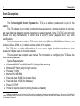
TechnologSoft
Control System
Version 2.00.00
User’s Manual
3
TechnologSoft
Contents
Short Description......................................................................................................................... 6
Organization of RS485 Communication Line ........................................................................... 8
Interface Description ................................................................................................................. 10
TCS Main Window .................................................................................................................... 10
Main Menu ............................................................................................................................... 12
Project Menu .......................................................................................................................... 12
User Menu.............................................................................................................................. 13
View Menu ............................................................................................................................ 13
Control Groups Menu ............................................................................................................ 14
Settings Menu ........................................................................................................................ 14
Tools Menu ............................................................................................................................ 16
Help Menu ............................................................................................................................. 16
Control Groups Toolbar ........................................................................................................... 17
Types of Data View ................................................................................................................... 17
Mnemonic .............................................................................................................................. 18
Graph ..................................................................................................................................... 19
Data Table .............................................................................................................................. 22
Control Page .......................................................................................................................... 23
Status Bar ................................................................................................................................. 25
Starting the Software ................................................................................................................ 26
4
TechnologSoft
User Login/Logout ..................................................................................................................... 27
Changing a user password ........................................................................................................ 29
Loading a Project ...................................................................................................................... 31
TCS Operating Modes............................................................................................................... 32
Real-Time Mode........................................................................................................................ 32
Archive View Mode ................................................................................................................... 32
Working with Archive ............................................................................................................... 33
Archive Types ........................................................................................................................... 33
Archive View ............................................................................................................................. 34
Loading Hardware Archive ...................................................................................................... 36
Event Log ................................................................................................................................... 38
Alarms and Emergencies .......................................................................................................... 42
Loss of Communication with Devices....................................................................................... 46
SMS Alarm ................................................................................................................................ 50
Critical Alarms ......................................................................................................................... 50
General Alarms......................................................................................................................... 51
SMS Delivery ............................................................................................................................. 53
TechnologSoft
5
Print............................................................................................................................................ 54
Printing Reports ....................................................................................................................... 54
Printing Graphs ........................................................................................................................ 56
Printing Data Tables ................................................................................................................ 56
Printing Reports on Schedule ................................................................................................... 57
Data Export ............................................................................................................................... 58
Data Export by Operator’s Demand ......................................................................................... 58
Data Export on Schedule .......................................................................................................... 58
Records....................................................................................................................................... 59
6
TechnologSoft
Short Description
The TechnologSoft Control System, the TCS, is a software product and is part of the
system.
The TCS allows you to control, monitor and manage devices in remote locations in real time,
and view historical data and generate reports for a selected period of time. The TSC can work with
devices from any manufacturer, for which there is an OPC server (supports DA1, DA2, DA3
specifications).
Device communication with the TCS can be both wired (Ethernet, RS485, MicroLAN etc.) and
wireless (X-Bee, GSM, etc.). It allows remote control of the system.
The TCS has a flexible differentiation of user access rights. Available simultaneous data
access for multiple users on the local network.
This document is a complete user manual. For information on configuring the TCS, see the
Administrator's Manual.
System Requirements:
• Windows 2000/XP pro/2003/Vista/7/8 (for Light/Net versions)
• Windows ХР Home (only for Light version)
• Processor 1 GHz
• Memory 512 MB RAM
• Free hard disk: 50 MB (for program files)
• Free hard disk: 10 GB (for database) 1
• Protocol TCP/IP
• Printer for reports (or/and if printing module is installed);
1
Database size depends on many factors such as the number of used devices, data archiving period, data hold time, etc. As soon as TechnologSoft is
installed, the database size is very small, but over time the files will grow. Depending on the amount of program use, database file size can reach a lot more
than indicated in this manual.
TechnologSoft
• GSM modem (if alarm SMS module is installed).
7
8
TechnologSoft
Organization of RS485 Communication Line
It is important to correctly install the RS485 communication lines. It is forbidden to have a
branching link. The network topology for the connection of devices is a common bus. See the
example in Figure 1.
Figure 1. Example of RS485 Installation
The wiring circuit is shown in Figure 2.
The ends of the link must be terminated. Terminator in this case is a resistor of 120 ohms,
which is connected between two signal lines A and B.
9
TechnologSoft
The line is connected to the computer via RS485/RS232 adapter directly to a physical COM
port or via RS485/USB adapter into the USB port (virtual COM port).
For critical facilities with continuous polling of devices it is strongly recommended to connect
the link to the physical COM port using RS485/RS232 adapter, as virtual COM ports can “hang”
sometimes because of the Windows O/S. It stops the data exchange and it cannot be retrieved
without human intervention.
Figure 2. Wire Connection
10
TechnologSoft
Interface Description
TCS Main Window
The main window of the TCS (Figure 3) consists of the following parts: the main menu, toolbar,
status bar and workspace.
The main menu is always at the top of the window. The status bar is always located at the
bottom of the window (the status bar can be turned off). All other space is called a workspace.
Toolbars may be displayed as floating windows located above the working area, or in the form of
windows attached to one of the edges of the working area.
Figure 3 shows a demonstration project. There is the Group toolbar at the top of the
workspace. It contains three control groups. Group 1 with four parameters and their values is
currently selected in the figure.
The status bar informs you that the current user is Administrator, that the database connection
is established and that there are no accidents or failures with the devices.
The working area of the main window displays the data as a graph with the parameters
according to the current settings of the control group. In this case, these are the same four
parameters which are in the group. One of the graph channels is off, so we only see three graphs.
The first two channels of the graph are attached to the Temperature axis, and the remaining two
channels to the Humidity axis, therefore both axes are displayed.
11
TechnologSoft
Figure 3. TCS Main Menu
12
TechnologSoft
Main Menu
The Main Menu is located at the top of the program window. Depending on the program
mode, the menu may vary.
Project Menu
The Project Menu (Figure 4) contains the basic operations of the project, as well as the print
commands. The list of available commands in this menu is presented in Table 1.
а)
b)
Figure 4. Project Menu
Table 1. List of Project Menu Commands
Command
Description
New
Creates a new project
Open…
Opens a current project from the database
Close
Closes the current project
Save
Saves the current project in the database. If it is a new project, the
software will prompt the user to enter a name.
TechnologSoft
13
Save as…
Saves the current project in the database under a different name,
i.e. creates a copy of the project.
Opens a print dialog box
Opens a print preview dialog box
Opens a print setup dialog box
Opens a page setup dialog box
Exits the program
Print…
Print Preview
Print Setup…
Page Setup…
Exit
User Menu
The User Menu (Figure 5) includes commands for user log in/out and password change.
Figure 5. User Menu
The Login command is used to verify the identity of the user and his or her rights to perform
different actions.
The Logout command logs user out of the TCS.
The Change Password command is the password change of the current user.
View Menu
The View Menu (Figure 6) contains the control commands of the program main window look
and types of data view.
The Toolbars and Docking Windows submenu has On/Off commands of available toolbars
in the current mode. Below is the list of types of data view available in the current mode.
The Restore Standard Windows Layout command restores the default configuration of the
toolbar location.
14
TechnologSoft
The Status Bar switch enables/disables the status bar.
Figure 6. View Menu
Control Groups Menu
The Control Groups Menu (Figure 7) contains configuration commands of control groups.
Figure 7. Control Groups Menu
The Add… command creates a new group.
The Edit… command changes configuration of the current control group.
The Delete command deletes the current group.
Settings Menu
The Settings Menu (Figure 8) contains all the configuration commands. The list of all
commands is presented in Table 2.
15
TechnologSoft
Figure 8. Settings Menu
Table 2. List of Settings Menu Commands
Command
Description
Control Groups…
Opens a dialog box with display settings of control groups
Mnemonic…
Opens a dialog box with display settings of a mnemonic
Graph…
Opens a dialog box with display settings of a graph
Table…
Opens a dialog box with display settings of a table
Alarm Conditions…
Opens a dialog box to configure alarm conditions
Loss of Communication… Opens a dialog box to reconfigure the communication system
SMS Alarm…
Opens a dialog box to configure SMS alarm
Scheduled Tasks…
Opens a dialog box to control scheduled tasks
User Rights…
Opens a dialog box to administer user rights
Language
Drop-down menu with the list of available interface languages
16
TechnologSoft
Tools Menu
The Tools Menu (Figure 9) contains commands of the various software tools.
The View Archive command switches to the archive view mode.
The Clear Archive command cleans the program archive of redundant files.
The Template Manager… command opens a dialog box for control of device templates.
The User’s Event Log… command opens the TCS Event Log.
The Loss of Communication Log… command opens the Communication Log.
The Alarm Log… command opens the Alarm Log.
The Make Record to Log command allows adding a record to the User’s Event Log.
.
Figure 9. Tools Menu
Help Menu
The Help Menu (Figure 10) contains help items relating to the TCS.
The About the program… command shows the information about the TCS.
Figure 10. Help Menu
TechnologSoft
17
Control Groups Toolbar
The floating group panel is a key element of control and can be attached to any side of the
window, or displayed as a separate window on top of the work area. The panel size can be
changed so as to select the optimal ratio of displayed information and its place on the work area. If
the group panel is closed, it can be opened through the View → Toolbars and Docking Windows
→ Control Groups menu. The group panel contains control groups.
The control group, further the group, is a logical set of control parameters and their display in
different types of data views. Each group has a name, a mnemonic and a set of parameters, and
further parameters. According to the setting, group parameters can be viewed directly in a group
window, in a graph, in a data table or in a control page. Each parameter can be displayed in only
one type of data view, for example, in a graph, and in all types at once. The same parameter can be
included in several different groups.
The values of the parameters in the group window are displayed in different colors depending
on the situation. If everything is OK, it is displayed in Normal color. If the point is an active alarm, it
is displayed in Alarm color 1. If there is a connection problem with a device, it is Alarm color 2. If
an upper or lower parameter value is violated, then it is Alarm color 3 or Alarm color 4
respectively. All the above mentioned colors are set by the administrator.
In each group, the administrator can configure a list of parameters which values can be
changed remotely (please refer to the Control Page section of the manual).
Types of Data View
The work area of the window displays the selected type of data view for the current group. It
can be a graph, a data table, a mnemonic or a control page.
To select a group, click on it. The selected group is highlighted in a special color.
18
TechnologSoft
Use the View Menu or toolbar buttons to select the type of data view. For a mnemonic press
the
button. For a graph press the
button. For a data table use the
button. And to go to a
button.
control page, use the
Mnemonic
To switch to a mnemonic, select the View → Mnemonic menu or press the appropriate toolbar
button. It will show a mnemonic for the current group (Figure 11). Each group can have its own
mnemonic, wherein the same mnemonic can be assigned to multiple groups. To see the mnemonic
for another group, select the desired group.
19
TechnologSoft
Figure 11. Example of Mnemonic
Graph
To switch to a graph, select the View → Graph menu or press the appropriate toolbar button.
The example of the graph is shown in Figure 3.
The graph always has the X axis, the axis of time. The Y axis (axis of values) can be several,
depending on the settings. But only the axes with attached parameters are displayed. The Y axis
may have unlimited number of parameters.
20
TechnologSoft
The symbols show the parameters of the current group which are selected for display on the
graph. When you change the group, the parameters of the new groups will be here.
The real-time graph is dynamically shifted along the time axis at a speed corresponding to the
selected scale.
According to the settings, the graph can display data for either a few minutes, hours or a few
days.
The format of titles on the time axis can be changed so that they give maximum information.
To do this, open the context menu on the time axis (Figure 12) and select the desired format.
Figure 12. Context Menu of Time Axis
At any time, some portion of the graph can be increased for more detailed consideration. To do
this, hold down the left mouse button and stretch the frame from left to right, and then release the
button. After that, the site caught in the area frame will be extended to the whole area of the graph.
If the frame is stretched from right to left, then the scale will be reduced. It is also possible to
change the scale using the mouse wheel (the third mouse button). In addition, the scale can be
changed for each axis separately. To do this, hold down the left mouse button on the desired axis
and move it left or right for the axis of time and up or down for the axes of values. When the desired
zoom is reached, release the mouse button. After the change of scale on the Y axis, when the
mouse is on this axis, the Auto Zoom pop-up button will appear. This button allows to choose the
scale of the Y-axis according to the data in the graph area.
It is also possible to move the graph by right-clicking. If the cursor is over the graph area, the
offset will be made on all axes. If the cursor is over a particular axis, the offset will occur only on this
axis.
TechnologSoft
21
If there is any manipulation with the graph movement or scaling on the X-axis, dynamic offset
on the axis of time will stop. It means that a graph displays a static picture. In the lower area of the
graph the Restore button will appear. By clicking on it you can return to the original position, i.e.
restore the scale on all axes and the dynamic offset on the axis of time.
Sometimes graphics can pile up on one another and it is difficult to determine the channels.
Therefore, it is possible to turn off any of the channels temporarily. To do this, hover over the area
of symbols, then there will be the >> pop-up button.
Clicking this button expands the area of symbols and displays a radio button beside each
channel. This button determines whether this channel will be displayed or not.
There is another way to quickly turn off all graph channels except one. For this purpose,
double click on the desired parameter of the current group. As a result, the graph will display only
one channel corresponding to the selected parameter. To quickly turn on all group channels, double
click on the group name.
For a detailed analysis of the data it is possible to set the cursor (Figure 13) by double-clicking
on the graph area. The cursor is a vertical line with a time stamp and windows, which contain the
values for each channel at that time. Windows with values can be moved with the mouse.
22
TechnologSoft
Figure 13. Cursor on the Graph
The cursor can be moved left/right with the mouse. To remove the cursor, right-click on it and
select Remove Cursor in the context menu.
Data Table
To switch to a data table, select the View → Table menu or press the appropriate toolbar
button.
The data table will show as many columns as parameters in the current group are selected to
display in the data table. Each parameter corresponds to a column. The number of rows will be
limited by either the maximum number of rows, or a period of time.
TechnologSoft
23
The most recent data will be in the top line. The oldest is at the bottom. When new data is
added, the new line will be at the top and the last line will be removed at the bottom.
Control Page
The Control Page is designed for remote control of devices.
Each group has a list of parameters which values can be changed by the user.
To switch to a control page, select the View → Control Page menu or press the appropriate
toolbar button. The example of control page is shown in Figure 14. This is the control page for
Group 2. Four parameters of this group are displayed for control.
To change the value of the parameter, press the ... button next to the desired parameter and
enter a new value in the dialog box.
24
TechnologSoft
Figure 14. Example of Control Page
TechnologSoft
25
Status Bar
The status bar is located at the bottom of the main window and displays basic information
about the state of the TCS. The status bar is divided into sections (left to right):
o Current status
o Indicator of long action progress
o Name of the current user
o Indicator of connection with configuration database
o Indicator of connection with software archive database
o Indicator of connection with hardware archive database
o Active alarm indicator (left-double-click on the indicator displays a list with information about all
active alarms)
o Indicator of communication with devices (left-double-click on the indicator displays a list of
parameters which have loss of communication)
Depending on the operating mode and the specific situation, the status bar may contain other
information.
For user convenience, when the mouse is on the individual sections of the status bar, tooltips
with more detailed information will appear.
If the status bar is disabled, it can be turned on using the View → Status Bar menu.
26
TechnologSoft
Starting the Software
To start the TechnologSoft program, use the menu command Start → All Programs →
TERA → TechnologSoft → TechnologSoft. After starting, the main program window will open
(Figure 3).
At first start the program may display a message that it is impossible to connect to the
database. And in the status bar the indicator of connection with database will be red. This situation
can occur in two cases:
1. If the database (Firebird) is on the same computer as the TechnologSoft program, but it is
not yet installed, is not configured or is not running. In this case, it is necessary to install,
configure or run the Firebird (please refer to Administrator's Manual).
2. If the database is on another computer. In this case, it is necessary to check and change
the settings of the configuration database (please refer to Administrator's Manual). Once
the connection to the database is restored, the indicator in the status bar changes color to
green.
The program is ready for operation. Log in to the program (please refer to the User
Login/Logout section of the manual) and open or create a new project.
TechnologSoft
27
User Login/Logout
To enter the program, run the User → Login command in the Main Menu. This command
opens a dialog for authorization, which is shown in Figure 15. Enter a user name and password in
the dialog box, and then press Login. If data is entered correctly, the dialog closes and the status
bar shows the name of the current user.
Figure 15. User Login
The User field in the dialog box is designed as a drop-down list. This makes it possible to enter
a user name from the keyboard or select it from the list. The list contains all the users in the
database.
NOTE. After installing the program, there is only one user, Administrator. The password for
this user by default is admin. This user is used for administration of user rights and program
settings.
WARNING! It is strongly recommended to change the password of Administrator in
order to avoid unauthorized access to the database and malicious actions that can be
performed even unintentionally.
To exit the program, run the User → Logout command in the Main Menu. After that the Login
failed line will show in the status line.
28
TechnologSoft
To change the user, log in again. A user can be changed at any time without interrupting the
control of the current process.
TechnologSoft
29
Changing a user password
Any user can change his password on his own. In addition, the password of any user can be
changed by the user with administrative user rights (please refer to Administrator's Manual).
To change the password, the user must log into the program and run the User → Change
Password command in the Main Menu. The Authorization Check box will open (Figure 16). In the
dialog box, enter the current password to make sure that the user of the computer is the one who is
logged into the program. After entering the password, click OK. If the correct password is entered,
the dialog closes.
Figure 16. Authorization Check
If user authorization is successfully validated, the Change Password dialog box will open.
This dialog is shown in Figure 17.
30
TechnologSoft
Figure 17. Change Password
In the dialog box, enter the new password twice and click OK. If the entered passwords are the
same, then the dialog box will close and the message about the successful password will appear.
TechnologSoft
31
Loading a Project
To start monitoring a desired object, load a corresponding project from the database. However,
first it is necessary to log into the program (please refer to the User Login/Logout section of the
manual).
The project is a configuration that describes the connection of devices, controlled parameters,
used types of data view, configuration backup, alarm conditions, and others.
To open a project, select the Project → Open... command (Figure 4) or use the corresponding
toolbar ( ).
At the same time it is possible to open only one project. Therefore, if it is necessary to go to
another project, first close the current project, and then load the second one.
Close the project by using the Project → Exit command (Figure 4).
Once the project is loaded, start communication using the Start button on the toolbar. From
this moment the TCS receives data in real time and displays them in a form that is currently
.
selected by the user. To stop communication, press the Stop button on the toolbar
Attention! After the computer restarts, the TCS does not start automatically. The user
must personally launch a program, log in, open the project and start communication. It
applies only to TechnologSoft client. Archive module starts automatically.
32
TechnologSoft
TCS Operating Modes
Real-Time Mode
Real-time mode is the main mode of the TCS. In this mode all types of data view are available
and the most recent data are displayed. Device remote control is also possible.
After the launch, the TCS goes automatically to real-time mode.
Archive View Mode
Archive view mode is designed to analyze the accumulated data, print reports and read
hardware archive. In this mode, the data is available in the form of data tables and graphs.
To switch to the archive view mode, run the Tools → View Archive (Figure 9) menu
command. To exit the archive view mode, run the Archive → Close command. After that, the TCS
goes to the real-time mode.
In this mode, the Archive toolbar is available (Figure 18).
TechnologSoft
33
Working with Archive
Archive Types
There are two types of archive: software and hardware. The first one means a constant
connection between the computer and devices, continuous operation of a special program (archive
module) and is used in cases where process technology is continuously monitored, or there is a
need for operational archiving or devices do not support archiving. The second one is used in cases
where there is no way to ensure constant communication between the computer and devices or
there is a need for duplication of information for greater reliability.
A software archive is formed by continuous communication with devices and recording the
current values in the archive database. It provides operational update of data in the archive and
does not require from devices to support the archiving function. Moreover, a software archive does
not depend on the device settings and has its own highly flexible configuration. However, a software
archive is completely dependent on the stable link with the devices. In case of loss of
communication or computer failure, current readings do not fall into the archive database, and socalled gaps, areas of time with no data, will appear.
A hardware archive is maintained by the device and stored in its internal memory. This is a
more reliable way to archive because the data is always saved until the device is turned on. The
gaps have much smaller probability of appearing than in the software archive. There is also no
need for constant communication between computer and devices. However, the hardware archive
should be read from time to time and stored in the database. Besides, this type of archive depends
on device settings, which do not provide sufficient flexibility.
Depending on the object of control, either software or hardware archive, or both together can
be used.
34
TechnologSoft
Archive View
To switch to the Archive View mode, run the Tools → View Archive menu command (Figure
9).
The archive can be read for each individual group. To do this, select a group, the period of
time, the archive type (software or hardware) and start the process of data loading.
The group is selected by left-clicking on the desired group on the group panel. The group is
highlighted by special color.
To select the period of time and the archive type, use the Archive toolbar (Figure 18). If the
Archive panel is closed, it can be opened via the View → Toolbars and Docking Windows →
. In the left column, select the date and start time, in
Archive menu or by using the toolbar button
the right column select the date and end time of period during which you need to look through the
archive data.
There is a radio button of archive type under the calendar. Specify the period of time and press
Load to start the data loading from the archive database. Loading can take different time depending
on the selected length of archiving period and pixel number in the group. Data loading can be
stopped at any time, by pressing the Break button.
35
TechnologSoft
Figure 18. Archive Toolbar
Once the loading process is completed, the archive for the current group will be shown. To see
the archive for another group, select the desired group and then click Load.
The archive can be represented as a graph or a data table. Select it by using commands of the
View Menu or by pressing the
and
toolbar buttons.
To exit from the Archive View mode, use the Archive → Close menu command. After that,
the TCS will return to the previous data view.
36
TechnologSoft
Loading Hardware Archive
To view the hardware archive, it is necessary to read the data directly from the device and
store it in the database. After that, the data will be available for viewing independently of the
connection with the device.
To load the data from the device and store it in the database, there should be connection with
the device. So make sure that the data collection is started (please refer to the Starting the
Software section of the manual). Next, go to the Archive View mode (Tools → View Archive),
select the period of time on the Archive panel and switch the Hardware Archive radio button. At
the same time, the Read From Device button will appear right from the radio button.
Attention! If data collection is not running, the Read From Device button will be inactive.
Then select the group and click the Read From Device button which will open a dialog box
with information about the progress of the query (Figure 19). Loading data from the device is quite a
lengthy process and can take several minutes. The duration of this procedure depends on the
interval time and the archiving period specified in the device.
At the end of the process, the dialog box with the result will appear. If successful, the software
will prompt to display the downloaded data in a form that is currently selected (graph or data table).
In case of failure, it will report about the error because of which it was not possible to obtain data.
37
TechnologSoft
Figure 19. Dialog with information about the progress of the query
38
TechnologSoft
Event Log
All events which the TCS generates are stored in the database for further processing. The list
of events can be viewed by selecting the Tools → User’s Event Log… menu. A dialog box of
user’s event log will appear (Figure 20).
39
TechnologSoft
Figure 20. User’s Event Log
When the dialog box is opened, the list of events for the current day is automatically loaded.
40
TechnologSoft
To see the list of events for a different time, specify the desired time range and then click
Load.
The time range is selected as follows. First, select the date and time since which to show
event, then select time range between the buttons 1 Hour, 8 Hours, 12 Hours, 1 Day, 3 Days, 7
Days. To see the list of events which start from the chosen date and time to the present, press the
Till Now button.
The log for each event has the following information:
o Event date and time
o User at that time
o Type of action
o Description of action
There is a list in the right part of the window to filter events by type. In this list, it is necessary
to select the types of desired events. When any type of event is selected or deselected, the event
list is dynamically updated to match the current filter. The event list can be sorted by any column of
the table. To sort the events, left-click on the column header. Another click on the header of that
column changes the sort direction.
Some events can have long descriptions. Therefore, for ease of viewing detailed information
on specific event, double-click on the line with the event of interest. It will open a dialog box with
information about this event (Figure 21).
41
TechnologSoft
Figure 21. Dialog with information about event
42
TechnologSoft
Alarms and Emergencies
While working in the data collection mode, all alarm conditions specified in the configuration
are analyzed. If any condition is violated, then the TCS generates an alarm event. At the same
time, the alarm sounds through the built-in speaker of PC system unit and external speakers if they
are connected to the PC sound card. Also, a dialog box of alarm acknowledgement will appear on
top of all windows. The frame of the dialog will be flashing, drawing the attention of the operator.
The Alarm acknowledgement dialog contains a list of active alarms and cannot be closed
until the operator acknowledges all alarms whether the alarm has been removed or not.
Acknowledge the alarm by pressing the Acknowledge button. Each alarm is acknowledged
separately. This ensures that the operator will be informed about all the alarms. Alarm message
includes the name, the parameter, for which alarm will be triggered and the time of an emergency. If
the alarm had been cancelled before it was acknowledged by the operator, there will be also the
time of cancel in the dialog box, but the dialog will still be expected for the operator to acknowledge
the alarm. The example of alarm acknowledgement dialog with one alarm in the list is shown in
Figure 22. When all alarms are acknowledged, the dialog box automatically closes and the audible
alarm will turn off.
43
TechnologSoft
Figure 22. Alarm Acknowledgement Dialog
Alarm acknowledgement through the dialog box is called software acknowledgement.
Some devices also support hardware acknowledgement, i.e. alarm acknowledgment from the
device keyboard. In this case, the same alarm message can be acknowledged either by hardware
or software. If the alarm is acknowledged by hardware, software acknowledgement is not required
and the dialog box will close without operator (if there are no more alarms in the list which require
acknowledgment).
When an alarm occurs, the corresponding indicator will appear in the status bar. When all
alarms are cancelled, the indicator will disappear. Double-click on this indicator will open a window
with a list of active alarms. Alarm condition is tied to a particular parameter, and if the parameter is
displayed in the group, then when the alarm condition is violated, its value will be displayed in
Alarm Color 1.
All events: appearance, acknowledgment and cancel of alarm are written in the alarm log.
Time of the event and the operator who was on duty when the alarm occurred, are always saved.
The only exception is hardware acknowledgment. In this case, only time of the alarm is written in
44
TechnologSoft
the alarm log (operator is not written). On this basis it can be determined how the alarm was
acknowledged: by software or hardware.
If hardware acknowledgment is supported, the software acknowledgment can be disabled. In
this case, when an alarm and acknowledgment dialog appear, the operator can click Acknowledge
and thus close the dialog box, but this event will not be recorded in the alarm log. Event
acknowledgment will be logged only if it is the hardware acknowledgment.
Alarm log can be opened by selecting the Tools → Alarm Log menu. Alarm log window will
appear on the screen (Figure 23). When the alarm log opens, the list of alarms for the current day
will be automatically loaded.
To see a list of alarms for different time, specify the range of time and then click Load. The
time range is selected similarly to the TCS event log.
The log for each alarm has the following information:
o Alarm name
o Alarm Parameter
o Alarm date and time
o Operator on duty when the alarm occurred
o Time of alarm acknowledgement
o Operator who performed the acknowledgment (if the operator is not specified, it means that
the alarm has been acknowledged by hardware)
o Time of alarm cancellation
o Operator on duty when the alarm was cancelled
45
TechnologSoft
The list of loaded alarms displays alarms in green color which have already been cancelled.
Highlighted in red are those alarms that are still active.
Alarm list can be sorted by any column of the table. To sort the events, left-click on the column
header. Double-click on the same column header changes the sort direction.
Figure 23. Alarm Log
.
46
TechnologSoft
Loss of Communication with Devices
In the communication mode each parameter receives new values from the data source. The
data source is typically a device. For various reasons, the communication with the devices can be
disrupted, for example, the loss of device power, break or interference in the communication line,
and others. The TCS reveals the loss of communication with data sources and reports it to the
operator, as well as logging the loss of communication. This occurs as follows.
If within a time period defined by the administrator the parameter fails to receive a new value
from the data source, the TCS generates a communication event regarding this parameter. At the
same time, this alarm sounds through the built-in speaker of PC system unit and external speakers
if they are connected to the PC sound card. Also, a communication dialog box will appear on top of
all windows. The frame of the dialog will be flashing, drawing the attention of the operator.
The dialog box contains a list of parameters which have loss of communication. The list
contains the names of parameters, time of start, and recovery of communication if it was restored
before the operator acknowledged the event. The dialog box will not be closed until the operator
acknowledges the loss of communication, even if the connection has been restored. This ensures
that the operator will be informed about all communication problems. All the parameters in the list
are acknowledged. To acknowledge the loss of communication, press the Acknowledge button in
the dialog box. After that, the dialog automatically closes and the audible alarm will turn off.
The example of communication dialog box is shown in Figure 24.
47
TechnologSoft
Figure 24. Loss of Communication Dialog Box
When a loss of communication is revealed, the corresponding indicator will appear in the
status bar. When the communication with all data sources is restored, the indicator will disappear.
Left-double-click on this indicator will open a window with a list of all data sources which have loss
of communication.
If the parameter which has loss of communication with its data source is displayed in the group
window, its value will be displayed in Alarm Color 2.
48
TechnologSoft
All events: loss, acknowledgment and restoration of communication by each parameter are
written in the loss of communication log. Time of the event and the operator who was on duty when
the event occurred, are always saved.
The loss of communication log can be opened by selecting the Tools → Loss of
Communication Log menu. The log window will appear on the screen (Figure 25). When you open
the log, the list of loss of communication events for the current day will be automatically loaded.
To see a list of events for different time, specify the time range and then click Load. The time
range is selected similarly to the TCS event log.
The log contains the following information:
o Parameter with loss of communication
o Date and time of communication fail
o Operator on duty when the fail occurred
o Time of fail acknowledgement
o Operator who performed the acknowledgment
o Time of communication restoration
o Operator on duty when the communication was restored
49
TechnologSoft
Figure 25. Loss of Communication Log
The list can be sorted by any column of the table. To sort the events, left-lick on the column
header. Double-click on the same column header changes the sort direction.
50
TechnologSoft
SMS Alarm
The SMS alarm system is another function of the TCS for more reliable control of the process
and rapid response of staff to emergencies.
This tool allows you to organize the delivery of messages about emergence, acknowledgment
and cancellation of alarms to specified phones. The length of the message in the SMS alarm
module is limited to one SMS. The maximum length of SMS is 70 characters. If the message has
more than 70 characters, the end of the message will be truncated.
An SMS alarm module and GSM-modem are required for SMS alarm operation.
The Administrator configures SMS alarm (please refer to Administrator Manual).
During configuration of the TCS, administrator specifies a list of alarms for SMS. Alarms that
were not included in this list will not be sent by SMS.
There are two levels of SMS alarms: general and critical alarms.
All other alarms that are not marked as critical are considered as general alarms.
Critical Alarms
Every critical alarm is processed separately and immediately by SMS. A separate message is
sent immediately after the event was recorded.
The Administrator sets the number of message repeats for active unacknowledged alarms and
the interval between such repeats.
The following messages can be sent for critical alarms depending on the settings:
o messages about a new alarm
o repeated messages about the active alarm if it has not yet been acknowledged by the operator
TechnologSoft
51
o messages about alarm acknowledgment if at the moment of acknowledgment the alarm has
not yet been cancelled or if the option of sending messages about alarm cancel is disabled
o message about alarm cancellation
The message text of a new alarm will include the name of the project, the time of message
creation, the current value of the parameter for which the alarm was triggered, the code and text
name of the alarm.
The text of repeated messages of active alarms will contain the same information, as well as
the number of repetitions.
The message text of alarm acknowledgment will include the name of the project, the time of
message creation, the alarm code and the operator who performed the acknowledgment. In the
case of hardware acknowledgment, the operator is not specified.
The message text of alarm cancellations will contain the same information, except for the
current value of the parameter for which the alarm was triggered.
General Alarms
The alarms of general level are processed together. Only one message is sent for all active
general alarms.
Messages about general alarms are sent with the delay that is specified by the administrator.
This delay gives for the operator to respond to the alarm. If the operator acknowledges all alarms
before the delay expires, the message will not be sent.
In addition, there is a Minimum SMS Pause for general alarms. In this parameter
administrator specifies the delay time before sending messages about general level of alarms. In
other words, the general alarm message may be sent only once no SMS message has been sent
within the predetermined time.
52
TechnologSoft
Also, the administrator sets the number of SMS repetitions for the active unacknowledged
alarms and the interval between repetitions.
The SMS regarding new alarms and repeated messages about current unacknowledged
alarms are only sent for general level of alarms. Messages about alarm acknowledgement and
cancellation are not sent. Messages of active alarms that have been acknowledged by the operator
are not sent. Messages of unacknowledged alarms that have already been canceled are not sent
either.
The SMS text of the general alarm will contain the name of the project, the time of message
creation, the number of active unacknowledged alarms and codes of these alarms. The text of
repeated messages will contain the same information, as well as the number of repetition.
TechnologSoft
53
SMS Delivery
The TCS supports the function of SMS delivery with the values of critical parameters. This
function allows to organize periodic delivery of messages with the current values of critical
parameters to the specified phones. Because of this, the service personnel or technician may
monitor processes remotely.
The administrator configures parameters of SMS delivery (please refer to Administrator
Manual).
SMS alarm module and GSM modem are required for SMS delivery.
54
TechnologSoft
Print
Print commands are in the Project Menu (Figure 4).
Printing Reports
To print a report, switch to the Archive View (please refer to the Archive View section of the
manual). On the Archive toolbar, select the desired time interval and click Report. If the project has
multiple report templates, first the Report Selection dialog opens (Figure 26) and then the Report
Creation dialog appears (Figure 27).
If the project has only one report template, the report selection dialog will be skipped.
Figure 26. Report Selection Dialog
On the Report Selection dialog, select the report template for printing in the dropdown list of
available reports.
55
TechnologSoft
Figure 27. Report Creation Dialog
On the Report Creation dialog, in the Include To Report section specify the type of
information in which it is necessary to display data (summary table, data table and/or graph).
In the Archive Type section, select the type of archive from which data should be loaded for
the report.
In the Select Parameters For Report section, choose a list of parameters that should be
included in the report.
Clicking on the OK button closes the dialog box and shows the layout of the generated report.
Then select the Project → Print... command of the main menu. This opens the standard print
dialog for the generated report.
56
TechnologSoft
Printing Graphs
Printing graphs is available in both Archive View and Real Time modes. To print a graph,
switch to the Graph type of data view and run the Project → Print... command of the main menu or
(Print) button on the toolbar. This will open the standard print dialog to select a printer.
press the
Printing Data Tables
Printing data tables is available in both Archive View and Real Time modes. To print a data
table, switch to the Table type of data view (View → Table menu command) and run the Project →
Print... command of the main menu or press the
(Print) button on the toolbar. This will open the
standard print dialog to select a printer.
Alternative way to print is to right-click on the table and choose Print in the context menu
(Figure 28).
Figure 28. Data Table Context Menu
TechnologSoft
57
Printing Reports on Schedule
Automatic printing reports on a schedule is done by print module and configured using the
printing tasks by administrator (please refer to Administrator Manual).
58
TechnologSoft
Data Export
The TCS supports the export of data in a delimited text file (format CSV). Data is exported by
operator’s demand or automatically on a schedule.
Data Export by Operator’s Demand
Data can be exported from both the data table of real-time and the data table of history.
To export the data, select the Table type of data view (View → Table menu command), call
the context menu of the table (Figure 28) and select Export Data to CSV File. This will open a
standard dialog box for file saving where the program prompt to enter a file name, select its location
on the disk and click Save.
Data Export on Schedule
Automatic data export on a schedule is done by data export module. Export data tasks are
configured by the administrator (please refer to Administrator Manual).
59
TechnologSoft
Records
The TCS allows operators to save the records in the event log. This ability is provided to
actions and events that cannot be fixed automatically, but will be useful in the subsequent analysis
of historical data.
To log the record, select the Tools → Make Record to Log command in the main menu. This
will open a dialog box that is shown Figure 29.
Figure 29. Logging a Record Dialog Box
60
TechnologSoft
On the dialog, enter a description of events or actions. The timestamp is automatically set to
the current time, but it can be changed if it is a record of some past event. After entering the
description, click OK and the record will be saved in the log.
To view previously saved records, open the event log (please refer to Event Log).