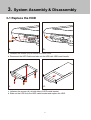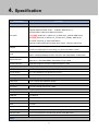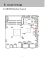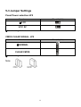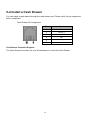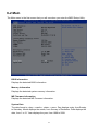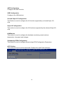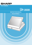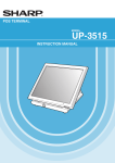
1
NPT-5851 User Manual Version V1.0 AUG 2012 Copyright 2012 All Rights Reserved Manual Version 1.0 Model Number: NPT-5851 The information contained in this document is subject to change without notice. We make no warranty of any kind with regard to this material, including, but not limited to, the implied warranties of merchantability and fitness for a particular purpose. We shall not be liable for errors contained herein or for incidental or consequential damages in connection with the furnishing, performance, or use of this material. This document contains proprietary information that is protected by copyright. All rights are reserved. No part of this document may be photocopied, reproduced or translated to another language without the prior written consent of the manufacturer. TRADEMARK 2nd generation Intel® Core™ brand are registered trademarks of Intel® Corporation. Microsoft® and Windows® are registered trademarks of Microsoft Corporation. Other names and brands may be claimed as the property of others. 1 Safety IMPORTANT SAFETY INSTRUCTIONS 1. To disconnect the machine from the electrical power supply, turn off the power switch and remove the power cord plug from the wall socket. 2. The wall socket must be easily accessible and in close proximity to the machine. 3. Read these instructions carefully. Save these instructions for future reference. 4. Follow all warnings and instructions marked on the product. 5. Do not use this product near water. 6. Do not place this product on an unstable cart, stand, or table. The product may fall, causing serious damage to the product. 7. Slots and openings in the cabinet and the back or bottom are provided for ventilation to ensure reliable operation of the product and to protect it from overheating. These openings must not be blocked or covered. The openings should never be blocked by placing the product on a bed, sofa, rug, or other similar surface. This product should never be placed near or over a radiator or heat register or in a built-in installation unless proper ventilation is provided. 8. This product should be operated from the type of power indicated on the marking label. If you are not sure of the type of power available, consult your dealer or local power company. 9. Do not allow anything to rest on the power cord. Do not locate this product where persons will walk on the cord. 10. Never push objects of any kind into this product through cabinet slots as they may touch dangerous voltage points or short out parts that could result in a fire or electric shock. 11. Never spill liquid of any kind on the product. 2 CE MARK . This device complies with the requirements of the EEC directive 2004/108/EC with regard to “Electromagnetic compatibility” and 2006/95/EC “Low Voltage Directive” This device complies with part 15 of the FCC rules. Operation is subject to the following two conditions: (1) This device may not cause harmful interference. (2) This device must accept any interference received, including interference that may cause undesired operation. CAUTION ON LITHIUM BATTERIES There is a danger of explosion if the battery is replaced incorrectly. Replace only with the same or equivalent type recommended by the manufacturer. Discard used batteries according to the manufacturer’s instructions. LEGISLATION AND WEEE SYMBOL 2002/96/EC Waste Electrical and Electronic Equipment Directive on the treatment, collection, recycling and disposal of electric and electronic devices and their components. The crossed dustbin symbol on the device means that it should not be disposed of with other household wastes at the end of its working life. Instead, the device should be taken to the waste collection centers for activation of the treatment, collection, recycling and disposal procedure. To prevent possible harm to the environment or human health from uncontrolled waste disposal, please separate this from other types of wastes and recycle it responsibly to promote the sustainable reuse of material resources. Household users should contact either the retailer where they purchased this product, or their local government office, for details of where and how they can take this item for environmentally safe recycling. Business users should contact their supplier and check the terms and conditions of the purchase contract. This product should not be mixed with other commercial wastes for disposal. 3 Revision History Changes to the original user manual are listed below: Version Date 1.0 AUG. 2012 Description Initial release 4 Table of Contents 1. Package Checklist……………................................................................. 1-1 1-2 1 Standard items…………………………………………………………………….. Optional items……………………………………………………………………... 1 1 2. System View………………………………………………………………...... 3. System Assembly & Disassembly………………………………………… 2 4 3-1 Replace the HDD…………………………………………………………………..... 3-2 Replace the Motherboard………………………………………………………….. 3-3 Replace the Inverter Board & Touch Board…………………………………..... 3-4 Install & Uninstall the Filter…………………………………............................... 3-5 Install VFD & MSR (Optional)…………………………………............................ 4 5 6 7 8 4. Specification………………………………………………………………….. 5. Jumper Settings……………………………………………………………… 9 11 5-1 HM-651 Motherboard Layout……………………………………………………… 5-2 Connectors Description……………………………………………………………. 5-3 Jumper Settings…………………………………………………………………….. 5-4 Install a Cash Drawer……………………………………………………………….. 11 12 13 14 6. BIOS Settings…………………………………………………………………. 15 6-1 About BIOS Setup………………………………………………………………….. 6-2 Main….………………………………………………………………………………… 6-3 Advanced…………………………………………………………………………….. 6-4 Chipset………………………………………………………………........................ 6-5 Boot……………………………………………………………………………………. 6-6 Security……………………………………………………………………………….. 6-7 Save & Exit…………………………………………………………………………… 15 17 19 31 36 37 38 Appendix…………………………………………………………………………. 39 5 1. Package Checklist 1-1 Standard items a. System b. power adapter 1-2 Optional items a. Second Display d. VFD b. Second Display (Pole Type) e. driver bank/e-User Manual 1 c. MSR f. power cord 2. System View Front View Rear View No. Description 1 Touch Screen 2 MSR/2-in-1 MSR (Option) 3 Power Button & Power LED 4 Model No. Label & OS License Label 5 Stand 6 Cables outlet 7 Heat sink Side View Top View No. Description 8 VFD (OPTION) 9 System Box (Inside with Motherboard) 10 Vesa Cover 11 Cables outlet 2 Rear I/O View No. Description 1 DC 19V IN 2 Cash Drawer Port 3 USB (x4) 4 LAN (10/100/1000) 5 COM(x4) 6 2nd VGA 7 DC 12V OUT 8 2.5 HDD 9 Parallel port 10 Line OUT 3 3. System Assembly & Disassembly 3-1 Replace the HDD a. b. a. Unfasten the screws (x2) to remove the HDD cover. b. Disconnect the HDD Cable and take out the HDD with HDD metal handle. c. d. c. Unfasten the screws (x4) at both sides of HDD metal bracket. d. Slide out the HDD from the HDD metal bracket and replace the HDD. 4 3-2 Replace the Motherboard To replace the motherboard, please follow the below steps: (1) Disconnect the HDD cable from the motherboard (Chapter 3-1, step a,b) (2) Open the system box to access the motherboard (See below) a. Unfasten the screws(x11) on the back of system box. b. Press the Front bezel then separate top and bottom chassis(L1、L2). c. Remove the LCD rear cover. d. Unfasten the screw(x8) fixing the motherboard and heatsink. e. Unfasten the screw(x4) fixing the motherboard. f. cable unplug out the motherboard with metal I/O bracket. 5 3-3 Replace the Inverter Board & Touch Board 3-3-1 Replace the Inverter Board a. The location of Inverter board on the LCD sheet metal bracket. b. Unfasten the screws (x2). c. Disconnect the cables (x3). 3-3-2 Replace the Touch Board a. The location of touch board on the LCD sheet metal bracket. b. Unfasten the screws (x2). c. Disconnect the cables (x2). 6 3-4 Install & Uninstall the Filter The device uses a filter that is washable and reusable. Insert the filter inside the pocket in the rear cover bracket, the handle backward the device and secure the filter with socket hole. Draw out the filter from the pocket in the rear cover bracket (Tip: get the snap out of the socket hole first) 7 3-5 Install VFD & MSR (Optional) 3-5-1 VFD install a. Unfasten the screws. b. Install VFD Module on the rear cover. c. Tighten the screws. 3-5-2 MSR install a. Unfasten the screws. b. Pull the MSR cover from rear cover. c. Install the MSR Module on the rear cover. d. Tighten the screws. 8 4. Specification Model Name NPT-5851 Motherboard NP-HM651 Default: Intel® Pentium® Processor B940, 2C/2T, 2.0 GHz, 2MB Cache; Upgrade Optional: B950, 2C/2T, 2.10GHz, 2MB Cache; or 2nd Generation Intel® Core Mobile Processor: Processor i7-2710QE, 4C/8T, BF_2.1GHz/ 1CT_3.0GHz/ 2CT_2.9GHz, 6MB Cache. i5-2510E, 2C/4T, BF_2.5GHz/ 1CT_3.1GHz/ 2CT_3.0GHz, 3MB Cache. i3-2330E, 2C/4T, BF_2.2GHz, 3MB Cache. Optional: Intel® Celeron® Processor B810, 2C/2T, 1.60 GHz, 2M Cache. Chipset PCH System Memory Graphic Memory Intel® vPro™ Technology Intel® Active Management Technology 7.0 paired with QM67 chipset. Default: Intel® BD82HM65 Platform Controller Hub, BD82HM65, FCBGA 989 Option: Intel® BD82QM67 Platform Controller Hub, BD82QM67, FCBGA 989 Default: 1 x SO-DIMM DDR3 1333 2GB; Optional: 2 x SO-DIMM DDR3 1600 Maximum up to 8GB Integrated graphics controller, Intel® HD Graphics 3000 LCD / Touch Panel LCD Size 15” TFT XGA (1024x768) 250cd/m² LCD panel Touch Screen 15" 5-wire Resistive Zero Bezel Touch Panel Tilt Angle 0° ~ 80° Storage Device Hard Drive 1 x 2.5" SATA HDD 320GB 5,400rpm Expansion mini-PCIe 1 x mini-Card slot (mini-PCIe / USB) Rear I/O Serial port 4 x RS-232 USB port 4 x USB 2.0 Parallel port 1 x Parallel LAN Port 1 x RJ-45 (10/100/1000Mbps Ethernet) VGA 1 x VGA Cash Drawer Port 1 x RJ-11, support 2 cash drawers (24V, Max 1.1A) DC-IN Jack 1 x 19V-IN DC-OUT Jack 1 x DC-12V Output for 2nd Display Power (12V, Max 3.0A) Line-OUT 1 x Line-OUT for Audio Audio 9 System Buzzer 1 x System Buzzer Internal Speaker 1 x 3W Speaker System Control/ Indicator Power Switch 1 x Power ON/OFF switch Power LED 1 x Power ON LED (Green) Power Power Supply External AC-DC 19V/ 6.31A 120W Power Brick Peripheral (Optional) MSR ISO 3 Tracks MSR (USB or PS/2) Customer Display 2 x 20 VFD customer display 2nd Display 15" LCD monitor Certificate EMC & Safety FCC Class A / CE / LVD Environment Operating Temperature 0°C ~ 40°C (32°F ~ 104°F) Storage Temperature -20°C ~ 60°C (-4°F ~ 140°F) Operating Humidity 20% - 80% RH non-condensing Storage Humidity 20% - 85% RH non-condensing Dimension 80° tilt angle 366(W) x 331(H) x 210(D) mm (No MSR) / 419(W) x 331(H) x 210(D) mm (w/ MSR) Display Head 366(W) x 280(H) x 64.5(D) mm (No MSR) / 419(W) x 280(H) x 64.5(D) mm (w/ MSR) Footprint 249 (W) x 209 (D) mm Package Size 490(L) x 390(W) x 350mm(H) (No MSR) / 560(L) x 390(W) x 350mm(H) (w/ MSR) Weight Net Weight 8.0kg (17.6lbs) Gross Weight 9.5kg (20.9lbs) OS Support Windows POSReady 2009,POS 7, Win 7 Pro, XP Pro, Win CE 6.0. Linux 2.6 / 2.4 (Ubuntu, SuSE, Fedora, CENTOS 2.6 Only) 10 5. Jumper Settings 5-1 HM-651 Motherboard Layout 11 5-2 Connectors Description Connector Purpose Connector Purpose CN2 CN4 CN6 CN8 CN10 CN12 CN14 COM5 Internal connector COM6 Internal connector MINI PCI-E LVDS Connector 48 Bit Line-out & MIC COM4 Internal connector DC-Power Input Connector CN3 CN5 CN7 CN9 CN11 CN13 SATA 3 Connector SATA 3 Connector Sim card holder LVDS Connector 48 Bit Print port VGA Connector CON1 CON3 CON5 MSR connector USB+LAN Connector SATA POWER Connector CON2 CON4 Power output connector CASH drawing connector J1 J4 J6 J8 J10 Internal USB connector Power on SW Battery socket Keyboard connector 4/5 Wire touch connector J2 J5 J7 J9 Internal USB connector Reset SW CCFL Connector Speaker OUT JP1 JP4 JP6 SATA/HD/LAN/POWER LED Backlight voltage selection SDVO connector JP2 JP5 JP7 CMOS / ME Clear LCD Power selection CASE OPEN Pin header 12 5-3 Jumper Settings Panel Power selection:JP5 Function JP1 (1-2) (2-3) JP1 (1-2) (2-3) ◎3.3V VCC 5V ◎Default setting 1-2 short. CMOS CLEAR SIGNAL: JP2 Function ◎NORMAL CLEAR CMOS ◎Default setting 1-2 short. Note: 13 5-4 Install a Cash Drawer You can install a cash drawer through the cash drawer port. Please verify the pin assignment before installation. Cash Drawer Pin Assignment Pin Signal 1 CASEOPEN2# 2 CASH1_P 3 CASEOPEN# 4 24V 5 CASH2_P 6 GND Cash Drawer Controller Register The Cash Drawer Controller use one I/O addresses to control the Cash Drawer. 14 6. BIOS Settings This chapter describes how to use the BIOS setup program for NPT-5850 Series. The BIOS screens in this chapter are for reference only and may change if the BIOS is updated in the future. To check for the latest updates and revisions, visit the NEXCOM Web site at www.nexcom.com.tw. 6-1 About BIOS Setup The BIOS (Basic Input and Output System) Setup program is a menu driven utility that enables you to make changes to the system configuration and tailor your system to suit your individual work needs. It is a ROM-based configuration utility that displays the system’s configuration status and provides you with a tool to set system parameters. These parameters are stored in non-volatile battery-backed-up CMOS RAM that saves this information even when the power is turned off. When the system is turned back on, the system is configured with the values found in CMOS. With easy-to-use pull down menus, you can configure such items as: ▪▪ Hard drives, diskette drives, and peripherals. ▪▪ Video display type and display options. ▪▪ Password protection from unauthorized use. ▪▪ Power management features. The settings made in the setup program intimately affect how the computer performs. It is important, therefore, first to try to understand all the Setup options, and second, to make settings appropriate for the way you use the computer. When to Configure the BIOS This program should be executed under the following conditions: ▪▪ When changing the system configuration. ▪▪ When a configuration error is detected by the system and you are ▪▪ prompted to make changes to the Setup program ▪▪ When resetting the system clock. ▪▪ When redefining the communication ports to prevent any conflicts. ▪▪ When making changes to the Power Management configuration. ▪▪ When changing the password or making other changes to the security setup. Normally, CMOS setup is needed when the system hardware is not consistent with the information contained in the CMOS RAM, whenever the CMOS RAM has lost power, or the 15 system features need to be changed. Default Configuration Most of the configuration settings are either predefined according to the Load Optimal Defaults settings which are stored in the BIOS or are automatically detected and configured without requiring any actions. There are a few settings that you may need to change depending on your system configuration. TO ENTER SETUP BEFORE BOOT PRESS <CTRL-ALT-ESC> Press the <Del>or<F2> key to enter Setup Key Right and Left arrows Up Function Moves the highlight left or right to select a menu. and Down arrows Moves the highlight up or down between submenus or fields. <Esc> Exits to the BIOS Setup Utility. + (plus key) Scrolls forward through the values or options of the highlighted field. - (minus key) Scrolls backward through the values or options of the highlighted field. <F1> Displays General Help. <F2> Previous Value <F3> Load optimized default setting <F4> Saves and exits the Setup program. <Enter> Press <Enter> to enter the highlighted sub menu. Scroll Bar When a scroll bar appears to the right of the setup screen, it indicates that here are more available fields not shown on the screen. Use the up and down arrow keys to scroll through all the available fields. Sub menu When ““ appears on the left of a particular field, it indicates that a submenu which contains additional options are available for that field. To display the submenu, move the highlight to that field and press <Enter> BIOS Setup Utility Once you enter the AMI BIOS Setup Utility, the Main Menu will appear on the screen. The main menu allows you to select from six setup functions and one exit choices. Use arrow keys to select among the items and press <Enter> to accept or enter the submenu. 16 6-2 Main The Main menu is the first screen that you will see when you enter the BIOS Setup Utility. BIOS Information Displays the detected BIOS information. Memory Information Displays the detected system memory information. ME Firmware Information Displays the detected ME Firmware information. System Date The date format is <day>, <month>, <date>, <year>. Day displays a day, from Sunday to Saturday. Month displays the month, from January to December. Date displays the date, from 1 to 31. Year displays the year, from 1999 to 2099. 17 System Time The time format is <hour>, <minute>, <second>. The time is based on the 24-hour military-time clock. For example, 1 p.m. is 13:00:00. Hour displays hours from 00 to 23. Minute displays minutes from 00 to 59. Second displays seconds from 00 to 59. 18 6-3 Advanced The Advanced menu allows you to configure your system for basic operation. Some entries are defaults required by the system board, while others, if enabled, will improve the performance of your system or let you set some features according to your preference. Setting incorrect field values may cause the system to malfunction. Legacy OpROM support Launch LAN PXE OpROM Enable or disable boot option for legacy network devices. Default: [Disabled] ACPI Setting This section is used to set the Advanced Configuration and Power Interface. CPU Configuration This section is used to configure the CPU. It will also display detected CPU information. SATA Configuration This section is used to configure the SATA drives. 19 AMT Configuration Configures the AMT function. USB Configuration Configures the USB devices. Second Super IO Configuration The Section is used to configure the I/O function supported by on board Super I/O chip. Super IO Configuration This section is used to configure the I/O functions supported by the onboard Super I/O chip. H/W Monitor This section is used to configure the hardware monitoring events such as temperature, fan speed and voltages. Sandybridge PPM Configuration This section is used to configure Sandy bridge PPM Configuration Parameters. ACPI Setting This section is used to set the Advanced Configuration and Power Interface. 20 Enables or Disable System ability to Hibernate (OS/S4 Sleep State). This option may be not effective with some OS. Default:[Enabled] ACPI Sleep State Select the highest ACPI sleep state the system will enter when the SUSPEND button is pressed. Default:[S3 (Suspend to RAM) CPU Configuration This section is used to configure the CPU. It will also display detected CPU information. 21 Hyper-Threading Enable this field for Windows XP and Linux which are optimized for Hyper-Threading technology. Select disabled for other OSes not optimized for Hyper-Threading technology. When disabled, only one thread per enabled core is enabled. Default:[Enabled] Hardware Prefetcher Turns on or off the MLC steamer prefetcher Default:[Enabled] Intel Virtualization Technology When this field is set to Enable, the VMM can utilize the additional hardware capabilities provided by Vanderpool technology. Default:[Disabled] 22 SATA Configuration This section is used to configure the SATA drives. SATA Mode SATA Controller Enble or disable SATA Device Default: [Enabled] SATA Mode Selection Determines how SATA controller(s) operate. Default: [IDE] 23 AMT Configuration Configures the Active Management Technology function. USB Configuration 24 Configures the USB devices. Legacy USB Support Enabled - Enables legacy USB. Auto - Disables support for legacy when no USB devices are connected. Disabled - Keeps USB devices available only for EFI applications. Default: [Enabled] EHCI Hand-off This is a workaround for OSes that does not support EHCI hand-off. TheEHCI ownership change should be claimed by the EHCI driver. Default: [Disabled] Second Super IO Configuration This section is used to configure the I/O functions supported by the onboard Super I/O chip. 25 Serial Port 3 Configuration to Serial Port 6 Configuration Selects the IO/IRQ setting of the I/O devices. 26 Super IO Configuration This section is used to configure the I/O functions supported by the onboard Super I/O chip. Serial Port 1 Configuration to Serial Port 2 Configuration This section is used to configure the I/O functions supported by the onboard Super I/O chip. Parallel Port Configuration Configures the parallel port 27 H/W Monitor This section is used to configure the hardware monitoring events such as temperature, fan speed and voltages. System Temperature 1 to System Temperature 2 and CPU core Temperature Detects and displays the internal temperature of the system. Fan1 Speed to Fan2 Speed Detects and displays the current system fan and CPU fan speed in RPM (Revolutions Per Minute). 28 Vcore to +5V Detects and displays the output voltages. Sandybridge PPM Configuration This section is used to configure Sandy bridge PPM Configuration Parameters. 29 EIST Enable/Disable Intel SpeedStep Default: [Disabled] CPU C3 Report Enable/Disable CPU C3(ACPI C2) report to OS Default: [Disabled] CPU C6 Report Enable/Disable CPU C6 (ACPI C6) report to OS Default: [Disabled] CPU C7 Report Enable/Disable CPU C7 (ACPI C7) report to OS Default: [Disabled] 30 6-4 Chipset System Agent (SA) Configuration System Agent (SA) Parameters PCH-IO Configuration PCH-IO parameters 31 Intel IGFX Configuration Selects the Graphic chip setting of Intel IGFX Configuration. Aperture Size Set Aperture Size Default:[256MB] DVNT Pre-Allocation Internal graphic memory size Default:[256M] DVMT Total GFX Mem Select DVNT5.0 total graphic memory size Default:[256M] 32 Primary IGFX Boot Display Select Video Device which will be activated during POS. This has no effect if external graphics present. Secondary boot display selection will appear based on your selection. VFA modes will be supported only on primary display. Default:[CRT] Secondary IGFX Boot Display Select Secondary Display Device Default: [LFP] LCD Panel Type Select LCD panel used by internal Graphics Device by selecting the appropriate setup item Default: [1024x768 LVDS] Panel color Depth Select the LFP Panel Color Depth Default: [18 Bit] LVDS Backlight Control Back Light Control Setting Default: [100%] 33 PCH-IO Configuration PCH-IO parameters PCH LAN Controller Enables or disables onboard NIC. Default: [Enable] Wake on LAN Enable Enables or disables integrated LAN to wake the system. Default: [Disabled] Azalia Control Detection of the Azalia device. Disabled - Azalia will be unconditionally disabled. 34 Enabled - Azalia will be unconditionally Enabled. Auto - Azalia will be enabled if present, disabled otherwise. Default: [Auto] SLP_S4 Assertion Width Select a minimum assertion width of the SLP_S4# signal Default: [4-5 Seconds] Restore AC Power Loss Select AC power state when power is re-applied after a power failure. Default: [Power off] 3G/ Wifi Module Type Allows BIOS to Select 3G/Wifi Module with/Without Voice function. Default: [without Voice] 35 6-5 Boot Quiet Boot Enables or disables the quiet boot function. Default: [Enable] Boot Option #1 and Boot Option #2 Selects the boot sequence of the hard drives. Hard Drive BBS Priorities Sets the order of the legacy devices in this group. 36 6-6 Security Administrator Password Sets the administrator password. User Password Sets the user password 37 6-7 Save & Exit Save Changes and Exit To save the changes and exit the Setup utility, select this field then press <Enter>. A dialog box will appear. Confirm by selecting Yes. You can also press <F4> to save and exit Setup. Discard Changes and Exit To exit the Setup utility without saving the changes, select this field then press <Enter>. You may be prompted to confirm again before exiting. You can also press <ESC> to exit without saving the changes. Load Optimized Default To restore / lead default all values for all the setup options. Confirm by selecting Yes to apply optimized default settings. 38 Appendix Drivers Installation: The shipping package includes a Driver CD. You can find every individual driver and utility that enables you to install the drivers in the Driver CD. Please insert the Driver CD into the drive and double click on the “index.htm” to pick up the models. You can refer to the drivers installation guide for each driverin the “Driver/Manual List”. 39