1
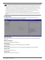
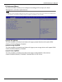
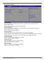
This equipment has been tested and found to comply with the limits of a Class B digital device,
responsible for any mistakes found in this user’s manual. All the brand and product names are
Ai sensi dell’art. 2 comma 3 del D.M. 275 del
30/10/2002
2004/108/CE, 2006/95/CE e 1999/05/CE
quando ad esso applicabili
We declare this product is complying with the
2004/108/CE, 2006/95/CE and 1999/05/CE
whenever these laws may be applied
Table Of Contents
............................................................................... 1
........................................................................................... 3
1.1 Before You Start .................................................................................................................. 3
1.2 Package Checklist ................................................................................................................ 3
...................................................................................................................... 4
............................................................................. 8
2.1 Installing Central Processing Unit (CPU) ............................................................................. 8
2.2 Install a Cooler .................................................................................................................... 9
2.3 Connect Cooling Fans ....................................................................................................... 10
2.4 Installing System Memory ................................................................................................ 10
2.5 Expansion Slots ................................................................................................................. 11
2.6 Power Supply .................................................................................................................... 11
2.7 Jumpers / Headers / Connectors ...................................................................................... 12
Chapter 3: BIOS Setup ........................................................................................... 21
3.1 Main Menu ....................................................................................................................... 22
3.2 Advanced Menu ................................................................................................................ 23
3.3 Chipset Menu.................................................................................................................... 37
3.4 Boot Menu ........................................................................................................................ 45
3.5 Security Menu................................................................................................................... 47
3.6 Exit Menu.......................................................................................................................... 48
Chapter 4: Useful help........................................................................................... 49
............................................................................................................. 49
4.2 AMI BIOS Beep Code......................................................................................................... 50
4.3 AMI BIOS post code .......................................................................................................... 50
................................................................................................................ 52
2 | Table Of Contents
BIH76-IHA User’s Manual
Chapter 1: Introduction
1.1 Before You Start
Thank you for choosing our product. Before you start installing the motherboard, please make
sure you follow the instructions below:
••• Prepare a dry and stable working environment with sufficient lighting.
••• Always disconnect the computer from power outlet before operation.
••• Before you take the motherboard out from anti-static bag, ground yourself properly
by touching any safely grounded appliance, or use grounded wrist strap to remove the
static charge.
••• Avoid touching the components on motherboard or the rear side of the board unless
necessary. Hold the board on the edge, do not try to bend or flex the board.
••• Do not leave any unfastened small parts inside the case after installation. Loose parts
will cause short circuits which may damage the equipment.
••• Keep the computer from dangerous area, such as heat source, humid air and water.
••• The operating temperatures of the computer should be 0 to 45 degrees Celsius.
••• To avoid injury, be careful of:
Sharp pins on headers and connectors
Rough edges and sharp corners on the chassis
Damage to wires that could cause a short circuit
1.2 Package Checklist
•••
•••
•••
•••
Mini-ITX Mainboard x 1
Fully Setup Driver DVD x 1
I/O Bracket x 1
SATA Cable x 1
Note
»»» The package contents may be different due to the sales region or models in which it was sold. For
more information about the standard package in your region, please contact your dealer or sales
representative.
Chapter 1: Introduction | 3
1.3
CPU
Chipset
Graphic
Super I/O
Main Memory
SATA
LAN
Sound Codec
Expansion Slot
Back Panel I/O
Socket G(rPGA-989) Support IVY & Sandy Bridge Intel® Core i5/i3 Dual Cores CPU
Support: Intel® Core i5-3210M (2.5GHz@35W)
Intel® Core i3-3110M (2.4GHz@35W)
Intel® Core i5-2540M (2.6GHz@35W)
Intel HM76 Express Chipset
Integrated Intel® HD Graphics 4000 series graphic engine supports:
Frequency: Intel® Core i5-3210M (GT2-4000) 350MHz-900MHz
Intel® Core i3-3110M (GT2-4000) 350MHz-900MHz
Intel® Core i5-2540M (GT2-3000) 650MHz-1100MHz
Dual independent displays (Extended mode) as below two:
-- Integrated VGA D-Sub
-- Integrated LVDS dual channel 18/24Bits
FINTEK F81866AD-I
2x SO-DIMM (204pin) Slot, DDR3 1333 MHz, Max 8GB
Registered DIMM or ECC DIMM is not supported
Chipset built-in Serial ATA controller
Data transfer rates up to 3.0/6.0 Gb/s
Realtek RTL 8111F
Realtek Codec ALC892, supports Line-out/Mic-in.
1x PCIe slot
1x Mini PCIe slot (with one SIM card signal connector)
1x DC-12V 4-pin Power Input Connector
1x VGA Port
1x RJ-11 Port
1x PS/2 Keyboard/ Mouse
1x RJ-45 Port
2x USB3.0 Port
2x USB2.0 Port
3x Serial Port
2x Audio Jack (Line-out/Mic-in)
2x SATA3 Connector
1x HDD Power Connector
1x Front Panel Header
1x CPU Fan Header
1x System Fan Header
1x Clear CMOS Jumper
On Board Connectors
1x LVDS Connector
& Headers
1x Inverter Header
1x LCD Backlight Inverter Power Select Jumper
1x LCD Panel Backlight Inverter Power Select Jumper
Board Size
OS Support
4|
2x Amplifier Header
3x USB 2.0 Header
170 mm (W) x 170 mm (L), Mini-ITX
4x Serial Port Header
4x Serial Port Power Select Jumper
2x RS-232/422/485 Select Jumper
1x RJ-11 Header for Cash Drawer
1x RJ-11 Power Select Jumper
1x Parallel Port Header
1x Digital I/O Header
1x MSR Connector
2x MSR Jumper
2x Power Connector
1x SIM Card Header
BIH76-IHA User’s Manual
1.4 Rear Panel Connectors
Standard
DC-12V Input Connector
Pin
1
2
3
4
Assignment
+12V DC_IN
GND
GND
+12V DC_IN
DC-12V Output Jack (Max. 2A)
RJ-11 pin define
Pin
1
2
3
4
5
6
Define
CASE OPEN#2
CASH1 _P
CASE OPEN#
CASH_PWR
CASH2_P
GND
Status Pin
CASE OPEN#2
--CASE OPEN#
-------
Control Pin
--CASH1 _P
----CASH2_P
---
GPIO
50
19
52
--21
---
ADD.
IO:538(BIT18)
IO:50C(BIT19)
IO:538(BIT20)
--IO:50C(BIT21)
---
|5
COM1 Connector
Pin
1
2
3
4
5
6
7
8
9
Assignment
Carrier detect (DCD)
Received data (RXD)
Transmitted data (TXD)
Data terminal ready (DTR)
Signal ground (GND)
Data set ready (DSR)
Request to send (RTS)
Clear to send (CTS)
Ring or 5V or 12V (selected by BIOS setting)
Pin
1
2
3
4
5
6
7
8
9
Assignment
Carrier detect (DCD)
Received data (RXD)
Transmitted data (TXD)
Data terminal ready (DTR)
Signal ground (GND)
Data set ready (DSR)
Request to send (RTS)
Clear to send (CTS)
0V or 5V or 12V (selected by BIOS setting)
Pin
1
2
3
4
5
6
7
8
9
Assignment
Carrier detect (DCD)
Received data (RXD)
Transmitted data (TXD)
Data terminal ready (DTR)
Signal ground (GND)
Data set ready (DSR)
Request to send (RTS)
Clear to send (CTS)
0V or 5V or 12V (selected by jumper setting)
COM2 Connector
COM3 Connector
Note
»»» Note1: COM1/2 voltage selection is controlled by BIOS setup. Please see page-34 for detail setting.
»»» Note2: COM1 RS-232/422/485 selection is controlled by JSEL1/JSEL2. Please see page-14 for detail
setting.
»»» Note3: COM3 voltage selection is controlled by JPC3. Please see page-15 for detail setting.
6 | Chapter 1: Introduction
BIH76-IHA User’s Manual
1.5 Motherboard Layout
Note
»»»
represents the 1st pin.
Chapter 1: Introduction | 7
Chapter 2: Hardware installation
2.1 Installing Central Processing Unit (CPU)
Step 1: Locate the CPU socket on the motherboard
Note
»»» Do not touch processor contacts to prevent damaging the CPU.
Step 2: Using a screwdriver, disengage (Unlock) the socket actuator, as shown in figure below.
Step 3: Align the gold triangle on the CPU with the similar marking on the socket. If the
processor does not drop completely into the socket, turn the socket actuator to the open
position until the processor drops completely in.
8 | Chapter 2: Hardware installation
BIH76-IHA User’s Manual
Step 4: While gently holding the processor down with your finger, secure the processor in the
socket with a screwdriver by turning the socket actuator to the “Lock” position.
Note
»»» The CPU fits only in one correct orientation. Do not force the CPU into the socket to prevent
damaging the CPU.
2.2 Install a Cooler
The system must not be operated without a cooler (heat sink and fan) to provide the
necessarily cooling. Install the cooling unit supplied as follows:
1. Install the correct CPU as described above.
2. Align the screw holes of the cooler rear retention bracket with the mounting holes on the
underside of the motherboard, located at the four corners of the CPU location. Insert into the
holes and turn the motherboard over.
3. Place the cooler assembly on top of the CPU with the cooling fins aligned with the memory
slots. This will allow the fan to provide cooling the chipset heatsink. Align the screws with the
screw holes of the rear retention bracket.
4. Tighten each screw halfway to secure the cooler assembly to the motherboard. Then
gradually tighten all four screws. Do not fully tighten the first screw before partially tightening
the other screws as this may apply uneven pressure to the CPU, causing damage.
Note
»»» Be careful not to touch the thermal pad on the underside of the heatsink. This pad is made of
thermal compound and is deformable. It is designed to make optimal thermal contact with the CPU.
No additional thermal compound is required.
»»» Make sure that good thermal contact is made between the processor and heat sink. Insufficient
contact or incorrect use of heat sink, fan, or thermal compound can cause the processor to
overheat, which may crash the system or cause permanent damage to the CPU.
»»» Do not forget to connect the CPU fan connector.
»»» For proper installation, please kindly refer to the installation manual of your CPU cooler.
Chapter 2: Hardware installation | 9
2.3 Connect Cooling Fans
These fan headers support cooling-fans built in the computer. The fan cable and connector
may be different according to the fan manufacturer. Connect the fan cable to the connector
while matching the black wire to pin#1.
CPU_FAN1: CPU fan header
SYS_FAN1: System fan header
CPU_FAN1
Pin Assignment
1
Ground
2
Smart Fan Control
3
FAN RPM rate sense
SYS_FAN1
Pin Assignment
1
Ground
2
+12V
3
FAN RPM rate sense
Note
»»» System Fan Headers support 3-pin head connectors. When connecting with wires onto connectors,
please note that the red wire is the positive and should be connected to pin#2, and the black wire is
Ground and should be connected to GND.
2.4 Installing System Memory
DIMMA1/B1: Memory Module (204pin SO-DIMM)
Note
»»» If the DIMM does not go in smoothly, do not force it. Pull it all the way out and try again.
1. Align a DIMM on the slot such that the notch on the DIMM matches the break on the Slot.
2. Insert the DIMM firmly into the slot until the retaining chip snap back in place and the
DIMM is properly seated.
Memory Capacity
DIMM Socket Location
DDR3 Module
DIMMA1
512MB/1GB/2GB/4GB
DIMMB1
512MB/1GB/2GB/4GB
10 | Chapter 2: Hardware installation
Total Memory Size
Max is 8GB
BIH76-IHA User’s Manual
2.5 Expansion Slots
PEX1_1: PCI-Express x1 Slot
••• PCI-Express 2.0 compliant.
••• Data transfer bandwidth up to 500MB/s per direction; 1GB/s in total.
••• PCI-Express supports a raw bit-rate of 2.5Gb/s on the data pins.
PE1: Mini PCI-E Slot (mSATA function is optional)
This mainboard is equipped with 1 Mini PCI-E Slot.
JSIM1: SIM card header
This mainboard is equipped with one SIM card header for Mini PCI-E Slot.
Pin
1
2
3
4
5
6
Assignment
GND
UIM_RESET
UIM_CLK
UIM_DATA
UIM_VPP
UIM_PWR
2.6 Power Supply
JPWR1: ATX Power Source Connector (4-pin)
This connector provides or +12V input to system power circuit.
Pin
1
2
3
4
Assignment
+12V in
+12V in
Ground
Ground
Chapter 2: Hardware installation | 11
JHDD1: HDD Power Connector
This connector provides power connection of SATA devices.
Pin
1
2
3
4
Assignment
+12V output
GND
GND
+5V output
Pin
1
2
3
4
Assignment
+12V output
GND
GND
NA
JP12V: 12V Output Power Connector
This connector provides power connection of 12V output.
2.7 Jumpers / Headers / Connectors
Jumper Setting
The illustration shows how to set up jumpers. When the jumper cap is placed on pins, the
jumper is “close”, if not, that means the jumper is “open”.
Pin opened
12 | Chapter 2: Hardware installation
Pin closed
Pin 1-2 closed
BIH76-IHA User’s Manual
JCMOS1: Clear CMOS Jumper
Placing the jumper on pin2-3 allows user to restore the BIOS safe setting and the CMOS data.
Please carefully follow the procedures to avoid damaging the motherboard.
1
3
Pin 1-2 Close: Normal Operation (Default)
3
1
Pin 2-3 Close: Clear CMOS data
Clear CMOS Procedures:
1. Remove AC power line.
2. Set the jumper to “Pin 2-3 close”.
3. Wait for five seconds.
4. Set the jumper to “Pin 1-2 close”.
5. Power on the AC.
6. Reset your desired password or clear the CMOS data.
JPANEL1: Front Panel Header
This 10-pin header includes Power-on, Reset, HDD LED, and Power LED connection. It allows
user to connect the system case’s front panel switch functions.
Function Pin Assignment Function
Pin Assignment
N/A
2
HDD LED
Reset
Button
1
Key
3
HD LED+
Power LED 4
Power LED+
5
HD LED-
6
Power LED-
7
Reset
8
Power
9
Reset GND
10
Power GND
Power
Button
Power LED
SATA1/SATA2: Serial ATA 6.0 Gb/s Connectors
These connectors support the thin Serial ATA cable for primary internal storage devices.
Pin
1
2
3
4
5
6
7
Assignment
Ground
TX+
TXGround
RXRX+
Ground
Chapter 2: Hardware installation | 13
F_USB1/2/3: USB 2.0 Header
The mainboard provides USB 2.0 pin header. Each header allows you to connect 2 additional
USB 2.0 ports.
Pin
1
3
5
7
9
Assignment
+5V (fused)
USB USB +
Ground
Key
Pin
2
4
6
8
10
Assignment
+5V (fused)
USB USB +
Ground
NC
Serial Port Connectors & Headers
JSEL1/JSEL2: RS-232/422/485 Switch Headers for COM1
The headers determine that COM1 belongs to RS-232 (Default), 422, or 485.
JSEL1
1-2
3-4
5-6
JSEL2
RS-232
1-3
2-4
7-9
8-10
RS-232
RS-422
RS-485
RS-422
3-5
4-6
9-11
10-12
RS-485
3-5
4-6
9-11
10-12
JCOM4: Serial Port Header
Pin
1
3
5
7
9
14 | Chapter 2: Hardware installation
Assignment
DCD
TXD
GND
RTS
Ring / 5V / 12V
Pin
2
4
6
8
10
Assignment
RXD
DTR
DSR
CTS
NA
BIH76-IHA User’s Manual
JPC4: Serial Port Voltage Switch Jumper for JCOM4
2
1
Pin 1-2 Close: Pin9=Ring (Default)
4
3
Pin 3-4 Close: Pin9= 5V
6
5
Pin 5-6 Close: Pin9=12V
JCOM3/JCOM5/JCOM6: Serial Port Headers
Pin
1
3
5
7
9
Assignment
DCD
TXD
GND
RTS
0V / 5V / 12V
Pin
2
4
6
8
10
Assignment
RXD
DTR
DSR
CTS
NA
JPC3/JPC5/JPC6: Serial Port Voltage Switch Jumpers for JCOM3/JCOM5/JCOM6
2
1
Pin 1-2 Close: Pin9=0V (Default)
4
3
Pin 3-4 Close: Pin9= 5V
6
5
Pin 5-6 Close: Pin9=12V
Chapter 2: Hardware installation | 15
JVGA1: VGA Connector (Optional)
This header allows you to connect VGA
Pin
1
2
3
4
5
6
7
8
9
10
Assignment
VGA_P5V
C_VGA_RED
VGA_5VDDCLK
C_VGA_GREEN
VGA_5VDDA
C_VGA_BLUE
VSYNC_C
GND
HSYNC_C
GND
JC1: LCD Backlight Inverter Connector
This connector is for connecting to LCD for providing backlight control function. It is strongly
recommended to use the matching JOY DAY INDUSTRIAL - A1250WV-S-8P connector.
Pin
1
2
3
4
5
6
7
8
16 | Chapter 2: Hardware installation
Assignment
DC 5V/12V (selected by JLV1)
DC 5V/12V (selected by JLV1)
NC
NC
Backlight On
Brightness Adjust
GND
GND
BIH76-IHA User’s Manual
LVDS-OUT1: LVDS Connector
This connector supports 18/24 bit single-channel panels.
»»» It is strongly recommended to use the matching JOY DAY INDUSTRIAL - A1252WV-SF-2X20PD01
connector.
Pin
1
3
5
7
9
11
13
15
17
19
21
23
25
27
29
31
33
35
37
39
Assignment
LVDSB_DATA0_N
LVDSB_DATA0_P
GND
LVDSB_DATA1_N
LVDSB_DATA1_P
GND
LVDSB_DATA2_N
LVDSB_DATA2_P
GND
LVDSB_CLK_N
LVDSB_CLK_P
GND
LVDSB_DATA3_N
LVDSB_DATA3_P
+5V
LVDSA_DDC-CLK
+3.3V
NC
PVDD2, 3.3V/5V (selected by JLV2)
PVDD2, 3.3V/5V (selected by JLV2)
Pin
2
4
6
8
10
12
14
16
18
20
22
24
26
28
30
32
34
36
38
40
Assignment
PVDD2, 3.3V/5V (selected by JLV2)
PVDD2, 3.3V/5V (selected by JLV2)
GND
GND
LVDSA_DATA0_N
LVDSA_DATA0_P
GND
LVDSA_DATA1_N
LVDSA_DATA1_P
GND
LVDSA_DATA2_N
LVDSA_DATA2_P
GND
LVDSA_CLK_N
LVDSA_CLK_P
GND
LVDSA_DATA3_N
LVDSA_DATA3_P
NC
LVDSA_DDC_DATA
JLV1: LCD Backlight Inverter Power Select Jumper
This jumper is for selecting LCD Backlight Inverter Power
1
3
Pin 1-2 Close: Inverter Power=5V
1
3
Pin 2-3 Close: Inverter Power=12V (Default)
Chapter 2: Hardware installation | 17
JLV2: LCD Panel Power Select Jumper
This jumper is for selecting LCD Power(PVDD2).
1
3
Pin 1-2 Close: Inverter Power=3.3V (Default)
1
3
1
3
1
3
Pin 2-3 Close: Inverter Power=5V
JLV3: Backlight Control Mode Selection Jumper
This jumper is for selecting backlight control mode.
Pin 1-2 Closed: Voltage Level Mode (Default)
Pin 2-3 Closed: PWM Mode
JSPK1/JSPK2: Amplifier Headers
JSPK1
Pin Assignment
1
SPKRN
2
SPKRP
JSPK2
Pin Assignment
1
SPKLN
2
SPKLP
18 | Chapter 2: Hardware installation
BIH76-IHA User’s Manual
JRJ11: Cash Draw Header
This onboard header is for cash drawer function, but when it is in use, you can not use the I/O
RJ11 connector.
Pin
1
2
3
4
5
6
Assignment
CASEOPEN#2
CASH1_P
CASEOPEN#
CASH_PWR
CASH2_P
GND
JP2: Voltage Switch Header for Cash Draw Connector
This header is for controlling the Pin4 of RJ11(JRJ11) to switch 12V or 24V.
1
3
1
3
Pin 1-2 Close: Pin4 of RJ11(JRJ11)=24V (Default)
Pin 2-3 Close: Pin4 of RJ11(JRJ11)=12V
JPRNT1: Printer Port Connector
This header allows you to connect printer port on the PC.
Pin
1
3
5
7
9
11
13
15
17
19
21
23
25
Assignment
-Strobe
Data 0
Data 1
Data 2
Data 3
Data 4
Data 5
Data 6
Data 7
-ACK
Busy
PE
SCLT
Pin
2
4
6
8
10
12
14
16
18
20
22
24
26
Assignment
-ALF
-Error
-Init
-Scltin
Ground
Ground
Ground
Ground
Ground
Ground
Ground
Ground
Key
Chapter 2: Hardware installation | 19
JDIO1: Digital I/O Connector
This connector offers 4-pair of digital I/O functions and address is set in BIOS.
Pin
1
2
3
4
5
6
7
8
9
10
Assignment
5V
DI-01
DO-01
DI-02
DO-02
DI-03
DO-03
DI-04
DO-04
GND
Address
-548H BIT7
50CH BIT7
548H BIT6
50CH BIT6
548H BIT5
50CH BIT1
548H BIT4
50CH BIT17
--
GPIO
-GPIO71
GPIO7
GPIO70
GPIO6
GPIO69
GPIO1
GPIO68
GPIO17
--
JMSR1: MSR Connector
The mainboard provides MSR connector.
Pin
1
2
3
4
5
6
Assignment
PS2CLK
PS2DAT
KCLK
KDAT
GND
+5V
JMSRS1/JMSRS2: MSR Jumper
The jumpers enable or disable MSR connector function.
1
3
1
3
Pin 1-2 Close:JMSR1 Disabled (Default)
Pin 2-3 Close: JMSR1 Enabled
20 | Chapter 2: Hardware installation
BIH76-IHA User’s Manual
Chapter 3: BIOS Setup
Introduction
The purpose of this manual is to describe the settings in the AMI UEFI BIOS Setup program on
this motherboard. The Setup program allows users to modify the basic system configuration
and save these settings to NVRAM.
UEFI BIOS determines what a computer can do without accessing programs from a disk. This
system controls most of the input and output devices such as keyboard, mouse, serial ports
and disk drives. BIOS activates at the first stage of the booting process, loading and executing
the operating system. Some additional features, such as virus and password protection or
chipset fine-tuning options are also included in UEFI BIOS.
The rest of this manual will to guide you through the options and settings in UEFI BIOS Setup.
Plug and Play Support
This AMI UEFI BIOS supports the Plug and Play Version 1.0A specification.
EPA Green PC Support
This AMI UEFI BIOS supports Version 1.03 of the EPA Green PC specification.
ACPI Support
AMI ACPI UEFI BIOS support Version 1.0/2.0 of Advanced Configuration and Power interface
specification (ACPI). It provides ASL code for power management and device configuration
capabilities as defined in the ACPI specification, developed by Microsoft, Intel and Toshiba.
PCI Bus Support
This AMI UEFI BIOS also supports Version 2.3 of the Intel PCI (Peripheral Component
Interconnect) local bus specification.
DRAM Support
DDR3 SDRAM (Double Data Rate III Synchronous DRAM) is supported.
Supported CPUs
This AMI UEFI BIOS supports the latest CPU.
Using Setup
When starting up the computer, press <Del> during the
Power-On Self-Test (POST) to enter the UEFI BIOS setup
utility.
In the UEFI BIOS setup utility, you will see General Help
description at the top right corner, and this is providing
a brief description of the selected item. Navigation
Keys for that particular menu are at the bottom right
corner, and you can use these keys to select item and
change the settings.
General Help
Navigation Keys
Chapter 3: BIOS Setup | 21
Note
»»» The default UEFI BIOS settings apply for most conditions to ensure optimum performance of the
motherboard. If the system becomes unstable after changing any settings, please load the default
settings to ensure system’s compatibility and stability. Use Load Setup Default under the Exit Menu.
»»» For better system performance, the UEFI BIOS firmware is being continuously updated. The
UEFI BIOS information described in this manual is for your reference only. The actual UEFI BIOS
information and settings on board may be slightly different from this manual.
»»» The content of this manual is subject to be changed without notice. We will not be responsible for
any mistakes found in this user’s manual and any system damage that may be caused by wrongsettings.
3.1 Main Menu
Once you enter AMI UEFI BIOS Setup Utility, the Main Menu will appear on the screen
providing an overview of the basic system information.
BIOS Information
Shows system information including UEFI BIOS version, model name, marketing name, built
date, etc.
Memory Frequency
Shows the system memory frequency.
Total Memory
Shows system memory size, VGA shard memory will be excluded.
System Date
Set the system date. Note that the ‘Day’ automatically changes when you set the date.
System Time
Set the system internal clock.
Access Level
Shows the access level of current user.
22 | Chapter 3: BIOS Setup
BIH76-IHA User’s Manual
3.2 Advanced Menu
The Advanced Menu allows you to configure the settings of CPU, Super I/O, Power
Management, and other system devices.
Note
»»» Beware of that setting inappropriate values in items of this menu may cause system to malfunction.
»»» The options and default settings might be different by RAM or CPU models.
Launch PXE OpROM
This item enables or disables boot Options for legacy network devices with option ROM.
Options: Disabled (Default) / Enabled
Launch Storage OpROM
This item enables or disables boot Options for legacy mass storage devices with option ROM.
Options:Enabled (Default) / Disabled
Launch Video OpROM
This item enables or disables execution of the legacy option ROM for video devices.
Options:Enabled (Default) / Disabled / Enabled when no UEFI Driver
Chapter 3: BIOS Setup | 23
PCI Subsystem Settings
PCI ROM Priority
In case of multiple option ROMs (Legacy and EFI Compatible), this item specifies what PCI
Option ROM to launch
Options: Legacy ROM (Default) / EFI Compatible ROM
Above 4G Decoding
Enables or disables 64bit capable device to be decoded in above 4G address space (only if
system support 64 bit PCI decoding).
Options: Disabled (Default) / Enabled
PCI Latency Timer
This item sets the value to be programmed into PCI Latency Timer Register.
Options: 32 PCI Bus Clocks (Default) / 64 PCI Bus Clocks / 96 PCI Bus Clocks / 128 PCI Bus Clocks
/ 160 PCI Bus Clocks / 192 PCI Bus Clocks / 224 PCI Bus Clocks / 248 PCI Bus Clocks
VGA Palette Snoop
Enables or disables VGA palette registers snooping.
Options: Disabled (Default) / Enabled
PERR# Generation
Enables or disables PCI device to generate SERR#.
Options: Disabled (Default) / Enabled
SERR# Generation
Enables or disables PCI device to generate SERR#.
Options: Disabled (Default) / Enabled
24 | Chapter 3: BIOS Setup
BIH76-IHA User’s Manual
PCI Express Settings
Relaxed Ordering
Enables or disables PCI express device No snoop option.
Options: Disabled (Default) / Enabled
Extended Tag
If enabled allows device to use 8-bit tab field as a requester.
Options: Disabled (Default) / Enabled
No Snoop
This item enables or disables PCI Express Device No Snoop option.
Options: Enabled (Default) / Disabled
Maximum Payload
This item sets Maximum Payload of PCI Express Device or allows System BIOS to select the
value.
Options: Auto (Default) / 128 Bytes / 256 Bytes / 512 Bytes / 1024 Bytes / 2048 Bytes / 4096
Bytes
Maximum Read Request
This item sets Maximum Read Request Size of PCI Express Device or allows System BIOS to
select the value.
Options: Auto (Default) / 128 Bytes / 256 Bytes / 512 Bytes / 1024 Bytes / 2048 Bytes / 4096
Bytes
ASPM
This item sets the ASPM (Active State Power Management Settings) Level: Force L0 – Force all
links to LO State; Auto – BIOS auto configures; Disabled – Disables ASPM.
Options: Disabled (Default) / Auto / Force L0s
Extend Synch
If enabled allows generation of extended synchronization patterns.
Options: Disabled (Default) / Enabled
Link Training Retry
Defines number of retry attempts software will take to retrain the link if previous training
attempt was unsuccessful.
Options: 5 (Default) / Disabled / 2 / 3
Chapter 3: BIOS Setup | 25
Link Training Timeout (uS)
Defines number of microseconds software will wait before polling ‘Link Training’ bit in link
status register. Value range is from 10 to 1000 uS.
Options: 100 (Default)
Unpopulated Links
In order to save power, software will disable unpopulated PCI Express links, if this option set to
‘Disable Link’.
Options: Keep Link ON (Default) / Disable Link
ACPI Settings
Enable ACPI Auto Configuration
This item enables or disables BIOS ACPI auto configuration.
Options: Disabled (Default) / Enabled
Enable Hibernation
This item enables or disables system ability to hibernate (OS/S4 sleep state)/ This option may
be not effective with some OS.
Options: Enabled (Default) / Disabled
ACPI Sleep State
This item selects the highest ACPI sleep state the system will enter when the SUSPEND button
is pressed.
Options: S1 (CPU Stop Clock) (Default) / Suspend Disabled / S3 (Suspend to RAM)
Lock Legacy Resources
This item enables or disables lock of legacy resources.
Options: Disabled (Default) / Enabled
S3 Video Repost
This item enables or disables S3 Video Repost..
Options: Disabled (Default) / Enabled
PME Wake up from S5
This item enables the system to wake from S5 using PEM event.
Options: Disabled (Default) / Enabled
26 | Chapter 3: BIOS Setup
BIH76-IHA User’s Manual
Wake system with Fixed Time
This item enables or disables the system to wake on by alarm event. When this item is enabled,
the system will wake on the hr::min::sec specified.
Options: Disabled (Default) / Enabled
Wake up date
You can choose which date the system will boot up.
Wake up hour / Wake up minute / Wake up second
You can choose the system boot up time, input hour, minute and second to specify.
USB Device Wakeup from S3/S4
This item allows you to enable or disabled the USB resume from S3/S4 function.
Options: Disabled (Default) / Enabled
Restore AC Power Loss
This item enables the system to wake from S5 using Ring-In event.
Options: Power Off (Default) / Power On / Last State
Ring-In Wake up from S5
This item enables the system to wake from S5 using Ring-In event.
Options: Disabled (Default) / Enabled
PS2 Keyboard PowerOn
This item allows you to control the keyboard power on function.
Options: Disabled (Default) / Ctrl + Esc / Ctrl + F1 / Ctrl + Space / Any Key / Wake Key / Power
Key / Ctrl + Alt + Space / Space
PS2 Mouse PowerOn
This item allows you to control the mouse power on function.
Options: Disabled (Default) / Enabled
CPU Configuration
Active Processor Cores
This item sets number of cores to enable in each processor package.
Options: All (Default) / 1 / 2 / 3
Chapter 3: BIOS Setup | 27
Limit CPUID Maximum
When the computer is booted up, the operating system executes the CPUID instruction to
identify the processor and its capabilities. Before it can do so, it must first query the processor
to find out the highest input value CPUID recognizes. This determines the kind of basic
information CPUID can provide the operating system.
Options: Disabled (Default) / Enabled
Execute-Disable Bit
XD can prevent certain classes of malicious buffer overflow attacks when combined with a
supporting OS (Windows Server 2003 SP1, Windows XP SP2, SuSE Linux 9.2, RedHat Enterprise
3 Update 3.).
Options: Enabled (Default) / Disabled
Intel Virtualization Technology
Virtualization Technology can virtually separate your system resource into several parts, thus
enhance the performance when running virtual machines or multi interface systems.
Options: Disabled (Default) / Enabled
Hardware Prefetcher
The processor has a hardware prefetcher that automatically analyzes its requirements and
prefetches data and instructions from the memory into the Level 2 cache that are likely to be
required in the near future. This reduces the latency associated with memory reads.
Options: Enabled (Default) / Disabled
Adjacent Cache Line Prefetch
The processor has a hardware adjacent cache line prefetch mechanism that automatically
fetches an extra 64-byte cache line whenever the processor requests for a 64-byte cache
line. This reduces cache latency by making the next cache line immediately available if the
processor requires it as well.
Options: Enabled (Default) / Disabled
TCC Activation offset
Offset from the factory TCC activation temperature
Options: 0 (Default)
CPU Max Current limit value (Amp)
The Maximum instantaneous current allow for Primary Plane.
IGFX Max Current limit value (Amp)
The Maximum instantaneous current allow for Secondary Plane.
28 | Chapter 3: BIOS Setup
BIH76-IHA User’s Manual
SATA Configuration
SATA Controller(s)
This item enables/disables Serial ATA Device.
Options: Enabled (Default) / Disabled
SATA Mode Selection
This item determines how SATA controller(s) operate.
Options: IDE (Default) / AHCI
* Note: mSATA function is optional.
USB Configuration
Legacy USB Support
This item determines if the BIOS should provide legacy support for USB devices like the
keyboard, mouse, and USB drive. This is a useful feature when using such USB devices with
operating systems that do not natively support USB (e.g. Microsoft DOS or Windows NT).
Options: Enabled (Default) / Disabled / Auto
Chapter 3: BIOS Setup | 29
USB3.0 Support
This item enables or disables USB3.0 (XHCI) controller support.
Options: Enabled (Default) / Disabled
XHCI Hand-Off
This is a workaround for OSes without XHCI hand-off support. The XHCI ownership change
should be claimed by XHCI driver.
Options: Enabled (Default) / Disabled
EHCI Hand-Off
This is a workaround for OSes without EHCI hand-off support. The EHCI ownership change
should be claimed by EHCI driver.
Options: Disabled (Default) / Enabled
Port 60/64 Emulation
This item enables I/O port 60h/64h emulation support. This should be enabled for the
complete USB keyboard legacy support for non-USB aware OSes.
Options: Enabled (Default) / Disabled
USB transfer time-out
The time-out value for Control, Bulk, and Interrupt transfers.
Options: 20 sec (Default) / 1 sec / 5 sec / 10 sec
Device reset time-out
The item sets USB mass storage device Start Unit command time-out.
Options: 20 sec (Default) / 10 sec / 30 sec / 40 sec
Device power-up delay
“Auto” uses default value: for a Root port it is 100ms, for a Hub port the delay is taken from
Hub descriptor.
Options: Auto (Default) / Manual
Device power-up delay in seconds
Delay range is 1 ~ 40 seconds, in one second increments.
Options: 5 (Default)
F81866 Super IO Configuration
30 | Chapter 3: BIOS Setup
BIH76-IHA User’s Manual
Serial Port 1 Configuration
Serial Port
This item enables or disables Serial Port (COM).
Options: Enabled (Default) / Disabled
Change Settings
This item selects an optimal setting for Super IO device.
Options: Auto (Default) / IO=3F8h; IRQ=4 / IO=3F8h; IRQ= 3, 4, 5, 6, 7,10, 11, 12 / IO=2F8h;
IRQ= 3, 4, 5, 6, 7,10, 11, 12 / IO=3E8h; IRQ= 3, 4, 5, 6, 7,10, 11, 12 / IO=2E8h; IRQ= 3, 4, 5, 6,
7,10, 11, 12
Serial Port 2 Configuration
Serial Port
This item enables or disables Serial Port (COM).
Options: Enabled (Default) / Disabled
Chapter 3: BIOS Setup | 31
Change Settings
This item selects an optimal setting for Super IO device.
Options: Auto (Default) / IO=2F8h; IRQ=3 / IO=3F8h; IRQ= 3, 4, 5, 6, 7,10, 11, 12 / IO=2F8h;
IRQ= 3, 4, 5, 6, 7,10, 11, 12 / IO=3E8h; IRQ= 3, 4, 5, 6, 7,10, 11, 12 / IO=2E8h; IRQ= 3, 4, 5, 6,
7,10, 11, 12
Serial Port 3 Configuration
Serial Port
This item enables or disables Serial Port (COM).
Options: Enabled (Default) / Disabled
Change Settings
This item selects an optimal setting for Super IO device.
Options: Auto (Default) / IO=2C0h; IRQ=6 / IO=3F8h; IRQ=6 / IO=2F8h; IRQ=6 / IO=2C0h; IRQ=6
/ IO=2C8h; IRQ=6 / IO=2D0h; IRQ=6 / IO=2D8h; IRQ=6
Serial Port 4 Configuration
Serial Port
This item enables or disables Serial Port (COM).
Options: Enabled (Default) / Disabled
32 | Chapter 3: BIOS Setup
BIH76-IHA User’s Manual
Change Settings
This item selects an optimal setting for Super IO device.
Options: Auto (Default) / IO=2C8h; IRQ=6 / IO=3F8h; IRQ=6 / IO=2F8h; IRQ=6 / IO=2C0h; IRQ=6
/ IO=2C8h; IRQ=6 / IO=2D0h; IRQ=6 / IO=2D8h; IRQ=6
Serial Port 5 Configuration
Serial Port
This item enables or disables Serial Port (COM).
Options: Enabled (Default) / Disabled
Change Settings
This item selects an optimal setting for Super IO device.
Options: Auto (Default) / IO=2D0h; IRQ=6 / IO=3F8h; IRQ=6 / IO=2F8h; IRQ=6 / IO=2C0h; IRQ=6
/ IO=2C8h; IRQ=6 / IO=2D0h; IRQ=6 / IO=2D8h; IRQ=6
Serial Port 6 Configuration
Serial Port
This item enables or disables Serial Port (COM).
Options: Enabled (Default) / Disabled
Chapter 3: BIOS Setup | 33
Change Settings
This item selects an optimal setting for Super IO device.
Options: Auto (Default) / IO=2D8h; IRQ=6 / IO=3F8h; IRQ=6 / IO=2F8h; IRQ=6 / IO=2C0h; IRQ=6
/ IO=2C8h; IRQ=6 / IO=2D0h; IRQ=6 / IO=2D8h; IRQ=6
UART IRQ Mode
This item allows you to determine PCI IRQ sharing for OS (EX. Windows) ISA IRQ for DOS.
Options: PCI IRQ Sharing (Default) / ISA IRQ
Parallel Port Configuration
Parallel Port
This item enables or disables Parallel Port (LPT/LPTE).
Options: Enabled (Default) / Disabled
Change Settings
This item allows you to select an optimal setting for Super IO device.
Options: Auto (Default) / IO=378h; IRQ=5 / IO=378h; IRQ=5, 6, 7, 10, 11, 12 / IO=278h; IRQ=5,
6, 7, 10, 11, 12 / IO=3BCh; IRQ=5, 6, 7, 10, 11, 12
Device Mode
This item allows you to determine how the parallel port should function.
Options: STD Printer Mode (Default) / SPP Mode / EPP-1.9 and SPP Mode / EPP-1.7 and SPP
Mode / ECP Mode / ECP and EPP 1.9 Mode / ECP and EPP 1.7 Mode /
UART1 RI Function
This item selects COM1 port pin 9 function.
Options: RING (Default) / +5V / +12V
UART2 RI Function
This item selects COM2 port pin 9 function.
Options: No any function (Default) / +5V / +12V
Watch Dog Degree
This item allows you to determine the functional degree of Watch Dog.
Options: Second (Default) / Minute
Watch Dog Timer
Options: 0 for disabled (Default) / Min=1, Max=65536
34 | Chapter 3: BIOS Setup
BIH76-IHA User’s Manual
Audio AMP
This item adjusts external audio amplifier.
Options: +11dB (Default) / +14dB / +19dB / +25dB
F81866 H/W Monitor
Shutdown Temperature
This item allows you to set up the CPU shutdown Temperature.
Options:Disabled (Default) / 70°C/158°F / 75°C/167°F / 80°C/176°F / 85°C/185°F / 90°C/194°F
Smart Fan Function
This item allows you to control the CPU Smart Fan function.
Options: Disabled (Default) / Enabled
CPU PPM Configuration
EIST
This item enables/disables Intel SpeedStep function.
Options: Enabled (Default) / Disabled
CPU C3/ C6/ C7 report
This item enables/disables C3 (ACPI C2)/ C6 (ACPI C3)/ C7 (ACPI C3) report to OS.
Options: Enabled (Default) / Disabled
Chapter 3: BIOS Setup | 35
Config TDP LOCK
This item allows you lock the config TDP control register..
Options: Disabled (Default) / Enabled
Long duration power limit
Long duration power limit in watts, 0 means factory default
Options: 120 (Default)
Long duration maintained
Time window which the long duration power is maintained
Options: 28 (Default)
Short duration power limit
Short duration power limit in watts, 0 means factory default
Options: 150 (Default)
ACPI T State
This item allows you enables/ disables ACPI T state support.
Options: Disabled (Default) / Enabled
36 | Chapter 3: BIOS Setup
BIH76-IHA User’s Manual
3.3 Chipset Menu
This section describes configuring the PCI bus system. PCI, or Personal Computer Interconnect,
is a system which allows I/O devices to operate at speeds nearing the speed of the CPU itself
uses when communicating with its own special components.
Note
»»» Beware of that setting inappropriate values in items of this menu may cause system to malfunction.
PCH-IO Configuration
Chapter 3: BIOS Setup | 37
PCI Express Configuration
Onboard Lan1 / PEX 1_1/ Mini PCIE Slot
This item controls the PCI Express Root Port.
Options: Enabled (Default) / Disabled
ASPM
This item sets PCI Express Active State Power Management settings.
Options: Auto(Default) / Disabled / L0s / L1 / L0sL1
PCIe Speed
This item selects PCI Express port speed.
Options: Auto (Default) / Gen1 / Gen2
USB Configuration
XHCI Pre-Boot Driver
This item enables or disables XHCI Pre-Boot Driver support.
Options: Enabled (Default) / Disabled
XHCI Mode
This item sets the mode of operation of XHCI controller.
Options: Smart Auto (Default) / Auto / Enabled / Disabled
38 | Chapter 3: BIOS Setup
BIH76-IHA User’s Manual
EHCI1/2
This item controls the USB EHCI (USB2.0) functions. One EHCI controller must always be
enabled.
Options: Enabled (Default) / Disabled
PCI Azalia Configuration
Azalia
This item controls detection of the Azalia device.
Disabled = Azalia will be unconditionally disabled.
Enabled = Azalia will be unconditionally Enabled.
Auto = Azalia will be enabled if present, disabled otherwise.
Options: Enabled (Default) / Disabled
Azalia HDMI codec
This item enables or disables internal HDMI codec Port for Azalia
Options: Enabled (Default) / Disabled
EuP Control
When EuP Enabled, System meets EuP requirement.
Options: Disabled (Default) / Enabled
SLP_S4# Min. Assertion Width
Options: 4 to 5 seconds (Default) / 1 to 2 seconds / 3 to 4 seconds / 2 to 3 seconds / Disabled
Chapter 3: BIOS Setup | 39
System Agent (SA) Configuration
Graphics Configuration
Primary Display
This item selects which of IGFX/PEG/PCI Graphics device should be Primary Display or select
SG for Switchable Gfx.
Options: Auto (Default) / IGFX / PEG
Internal Graphics
This item keeps IGD enabled based on the setup options.
Options: Auto (Default) / Disabled / Enabled
GTT Size
This item selects GTT Size.
Options: 2MB (Default) / 1MB
Aperture Size
This item selects Aperature Size.
Options: 256MB (Default) / 128MB / 512MB
40 | Chapter 3: BIOS Setup
BIH76-IHA User’s Manual
DVMT Pre-Allocated
This item selects DVMT 5.0 Pre-Allocated (Fixed) Graphics Memory size used by the Internal
Graphics Device.
Options: 64M (Default) / 32M / 96M / 128M / 160M / 192M / 224M / 256M / 288M / 320M /
352M / 384M / 416M / 448M / 480M / 512M / 1024M
DVMT Total Gfx Mem
This item selects DVMT5.0 Total Graphic Memory size used by the Internal Graphics Device.
Options: 256MB (Default) / 128MB / MAX
Gfx Low Power Mode
This option is applicable for SFF only
Options: Disabled (Default) / Enabled
Graphics Performance Analyzers
This item is enables/ disables Intel graphics performance analyzers counters.
Options: Disabled (Default) / Enabled
LCD Control
Primary IGFX Boot Display
This item selects the video device which will be activated during POST. This has no effect if
external graphics present.
Options: VBIOS Default (Default) / CRT / LVDS / HDMI (optional)
LCD Panel Type
This item selects the LCD panel used by Internal Graphics Device by selecting the appropriate
setup item.
Options: VBIOS Default (Default) / 640 x 480 / 800 x 600 / 1024 x 768 / 1280 x 1024 / 1400 x
1050(RB) / 1400 x 1050 / 1600 x 1200 / 1366 x 768 / 1680 x 1050 / 1920 x 1200 / 1440 x 900 /
1600x 900 / 1024 x 768 / 1280 x 800 / 1920 x 1080 / 2048 x 1536
Panel Scaling
This item selects the LCD panel scaling option used by the Internal Graphics Device.
Options: Auto (Default) / Force Scaling / Off
LVDS Brightness
This item selects the LCD panel brightness percentage.
Chapter 3: BIOS Setup | 41
Backlight Control
This item selects Back Light Control Setting
Options: BackLight Inverted (Default) / BackLight Normal
Spread Spectrum clock Chip
>>Hardware: Spread is controlled by chip; >>Software: Spread is controlled by BIOS
Options: Off (Default) / Hardware / Software
Active LFP
This item selects the Active LVDS Configuration. No LVDS: VBIOS does not enable LVDS; IntLVDS: VBIOS enables LVDS driver by integrated encoder.
Options: Int-LVDS (Default) / No LVDS
Panel Color Depth
This item selects the LFP Panel Color Depth
Options: 18Bit (Default) / 24Bit
Memory Configuration
Memory Insight
DDR3_A1/B1 Information
These items display SPD information of DDR3 memory.
42 | Chapter 3: BIOS Setup
BIH76-IHA User’s Manual
DIMM Profile
Select DIMM timing profile that should be used.
Options: Default DIMM profile (Default) / Custom Profile
Custom Profile Control
CAS# Latency (tCL)
This item allows you to select CAS Latency of DDR3.
Options: 9 (Default) / 3 ~ 15
RAS# to CAS# Delay (tRCD)
This item allows you to select Row Address to Column Address Delay of DDR3.
Options: 9 (Default) / 3 ~ 15
Row Precharge Time (tRP)
This item allows you to select Row Precharge Time of DDR3.
Options: 9 (Default) / 3 ~ 15
RAS# Active Time (tRAS)
This item allows you to select Row Active Time of DDR3.
Options: 24 (Default) / 9 ~ 63
Write Recovery Time (tWR)
This item allows you to select Internal Write to Read Command Delay of DDR3.
Options: 10 (Default) / 3 ~ 31
Row Refresh Cycle Time (tRFC)
This item allows you to select Minimum Refresh Recovery Time of DDR3.
Options: 107 (Default) / 15 ~ 255
Active to Active Delay (tRRD)
This item allows you to select Row Active to Row Active Delay of DDR3.
Options: 4 (Default) / 4 ~ 15
Write to Read Delay (tWTR)
This item allows you to select Internal Write to Read Command Delay of DDR3.
Options: 5 (Default) / 3 ~ 31
Read CAS# Precharge (tRTP)
This item allows you to select Read to Precharge Delay of DDR3.
Options: 5 (Default) / 4 ~ 15
Chapter 3: BIOS Setup | 43
Four Active Window Delay (tFAW)
This item allows you to select Four Active Window Delay of DDR3.
Options: 20 (Default) / 4 ~ 63
Memory Frequency Limiter
Maximum Memory Frequency Selections in MHz.
Options: Auto (Default) / 1067 / 1333
Max TOLUD
This item sets maximum value of TOLUD. Dynamic assignment would adjust TOLUD
automatically based on largest MMIO length of installed graphic controller.
Options: Dynamic (Default) / 1 GB / 1.25 GB / 1.5 GB / 1.75 GB / 2 GB / 2.25 GB / 2.5 GB / 2.75
GB / 3 GB / 3.25 GB
Memory Scrambler
This item enables or disables memory scrambler support.
Options: Enabled (Default) / Disabled
MRC Fast Boot
This item enables or disables MRC Fast Boot.
Options: Enabled (Default) / Disabled
Scrambler Seed Generation Off
This item sets control memory scrambler seed generation.
Enable – do not generation scrambler seed. Disable – generation scrambler seed always.
Options: Disabled (Default) / Enabled
Memory Remap
This item enables or disables memory remap above 4G.
Options: Enabled (Default) / Disabled
44 | Chapter 3: BIOS Setup
BIH76-IHA User’s Manual
3.4 Boot Menu
This menu allows you to setup the system boot options.
Setup Prompt Timeout
This item sets number of seconds to wait for setup activation key.
Options: 2 (Default)
Bootup NumLock State
This item selects the keyboard NumLock state.
Options: On (Default) / Off
Full Screen LOGO Display
This item allows you to enable/disable Full Screen LOGO Show function.
Options: Enabled (Default) / Disabled
Fast Boot
This item allows you to enable/disable Full Screen LOGO Show function.
Options: Disabled (Default) / Enabled
Skip VGA
If enabled, BIOS will skip EFI VGA driver.
Options: Disabled (Default) / Enabled
Skip USB
If enabled, USB devices will not be available until after OD boot. If disabled, USB device will be
available before OS boot.
Options: Disabled (Default) / Enabled
Skip PS2
If enabled, PS2 devices will be skipped.
Options: Disabled (Default) / Enabled
GateA20 Active
Upon Request – GA20 can be disabled using BIOS services. Always – do not allow disabling
GA20; this option is useful when any RT code is executed above 1MB
Options: Upon Request (Default) / Always
Chapter 3: BIOS Setup | 45
Option ROM Messages
This item sets the display mode for Option ROM.
Options: Force BIOS (Default) / Keep Current
Interrupt 19 Capture
Interrupt 19 is the software interrupt that handles the boot disk function. When set to
Enabled, this item allows the option ROMs to trap interrupt 19.
Options: Enabled (Default) / Disabled
CSM Support
This item enables / disables CSM Support. If Auto is selected, based on OS, CSM will be
enabled / disabled automatically.
Options: Enabled (Default) / Disabled / Auto
Boot Success Beep
When this item is set to Enabled, BIOS will let user know boot success with beep.
Options: Enabled (Default) / Disabled
UEFI oot
This option enables/disables boot from the UEFI Devices.
Options: Disabled (Default) / Enabled
46 | Chapter 3: BIOS Setup
BIH76-IHA User’s Manual
3.5 Security Menu
Administrator Password
This item sets Administrator Password.
User Password
This item sets User Password.
Chapter 3: BIOS Setup | 47
3.6 Exit Menu
This menu allows you to load the optimal default settings, and save or discard the changes to
the BIOS items.
Discard Changes and Exit
Abandon all changes made during the current session and exit setup.
Save Changes and Reset
Reset the system after saving the changes.
Restore Defaults
This selection allows you to reload the BIOS when problem occurs during system booting
sequence. These configurations are factory settings optimized for this system.
48 | Chapter 3: BIOS Setup
BIH76-IHA User’s Manual
Chapter 4: Useful help
4.1 Driver Installation
After you installed your operating system, please insert the Fully Setup Driver DVD into your
optical drive and install the driver for better system performance.
You will see the following window after you insert the DVD
The setup guide will auto detect your motherboard and operating system.
Note
»»» If this window didn’t show up after you insert the Driver DVD, please use file browser to locate and
execute the file SETUP.EXE under your optical drive.
A. Driver Installation
To install the driver, please click on the Driver icon. The setup guide will list the compatible
driver for your motherboard and operating system. Click on each device driver to launch the
installation program.
B. Software Installation
To install the software, please click on the Software icon. The setup guide will list the software
available for your system, click on each software title to launch the installation program.
C. Manual
Aside from the paperback manual, we also provide manual in the Driver DVD. Click on the
Manual icon to browse for available manual.
Note
»»» You will need Acrobat Reader to open the manual file. Please download the latest version of Acrobat
Reader software from http://www.adobe.com/products/acrobat/readstep2.html
Chapter 4: Useful help | 49
4.2 AMI BIOS Beep Code
Boot Block Beep Codes
Number of Beeps
Continuing
Description
Memory sizing error or Memory module not found
POST BIOS Beep Codes
Number of Beeps
1
8
Description
Success booting.
Display memory error (system video adapter)
4.3 AMI BIOS post code
Checkpoint Description
03
04
05
06
07
08
C0
C1
C2
C5
C6
C7
0A
0B
0C
0E
13
20
24
2A
2C
2E
31
33
37
38
39
3A
3B
3C
Disable NMI, Parity, video for EGA, and DMA controllers. Initialize BIOS, POST, Runtime data area. Also
initialize BIOS modules on POST entry and GPNV area. Initialized CMOS as mentioned in the Kernel Variable
“wCMOSFlags.”
Check CMOS diagnostic byte to determine if battery power is OK and CMOS checksum is OK. Verify CMOS
checksum manually by reading storage area. If the CMOS checksum is bad, update CMOS with power-on
default values and clear passwords. Initialize status register A.
Initializes data variables that are based on CMOS setup questions.
Initializes both the 8259 compatible PICs in the system
Initializes the interrupt controlling hardware (generally PIC) and interrupt vector table.
Do R/W test to CH-2 count reg. Initialize CH-0 as system timer. Install the POSTINT1Ch handler. Enable IRQ-0
in PIC for system timer interrupt.
Traps INT1Ch vector to “POSTINT1ChHandlerBlock.”
Fixes CPU POST interface calling pointer.
Initializes the CPU. The BAT test is being done on KBC. Program the keyboard controller command byte is
being done after Auto detection of KB/MS using AMI KB-5.
Early CPU Init Start -- Disable Cache – Init Local APIC.
Set up boot strap processor Information.
Set up boot strap processor for POST.
Enumerate and set up application processors.
Re-enable cache for boot strap processor.
Early CPU Init Exit.
Initializes the 8042 compatible Key Board Controller.
Detects the presence of PS/2 mouse.
Detects the presence of Keyboard in KBC port.
Testing and initialization of different Input Devices. Also, update the Kernel Variables.
Traps the INT09h vector, so that the POST INT09h handler gets control for IRQ1. Uncompress all available
language, BIOS logo, and Silent logo modules.
Early POST initialization of chipset registers.
Relocate System Management Interrupt vector for all CPU in the system.
Uncompress and initialize any platform specific BIOS modules. GPNV is initialized at this checkpoint.
Initializes different devices through DIM.
See DIM Code Checkpoints section of document for more information.
Initializes different devices. Detects and initializes the video adapter installed in the system that have optional
ROMs.
Initializes all the output devices.
Allocate memory for ADM module and uncompress it. Give control to ADM module for initialization. Initialize
language and font modules for ADM. Activate ADM module.
Initializes the silent boot module. Set the window for displaying text information.
Displaying sign-on message, CPU information, setup key message, and any OEM specific information.
Initializes different devices through DIM. See DIM Code Checkpoints section of document for more information.
USB controllers are initialized at this point.
Initializes DMAC-1 & DMAC-2.
Initialize RTC date/time.
Test for total memory installed in the system. Also, Check for DEL or ESC keys to limit memory test. Display
total memory in the system.
Mid POST initialization of chipset registers.
50 | Chapter 4: Useful help
BIH76-IHA User’s Manual
Checkpoint Description
40
52
60
75
78
7C
84
85
87
8C
8D
8E
90
A1
A2
A4
A7
A9
AA
AB
AC
B1
00
Detect different devices (Parallel ports, serial ports, and coprocessor in CPU, etc.) successfully installed in the
system and update the BDA, EBDA…etc.
Updates CMOS memory size from memory found in memory test. Allocates memory for Extended BIOS
Data Area from base memory. Programming the memory hole or any kind of implementation that needs an
adjustment in system RAM size if needed.
Initializes NUM-LOCK status and programs the KBD typematic rate.
Initialize Int-13 and prepare for IPL detection.
Initializes IPL devices controlled by BIOS and option ROMs.
Generate and write contents of ESCD in NVRam.
Log errors encountered during POST.
Display errors to the user and gets the user response for error.
Execute BIOS setup if needed / requested. Check boot password if installed.
Late POST initialization of chipset registers.
Build ACPI tables (if ACPI is supported).
Program the peripheral parameters. Enable/Disable NMI as selected.
Initialization of system management interrupt by invoking all handlers. Please note this checkpoint comes right
after checkpoint 20h.
Clean-up work needed before booting to OS.
Takes care of runtime image preparation for different BIOS modules. Fill the free area in F000h segment with
0FFh. Initializes the Microsoft IRQ Routing Table. Prepares the runtime language module. Disables the system
configuration display if needed.
Initialize runtime language module. Display boot option popup menu.
Displays the system configuration screen if enabled. Initialize the CPU’s before boot, which includes the
programming of the MTRR’s.
Wait for user input at config display if needed.
Uninstall POST INT1Ch vector and INT09h vector.
Prepare BBS for Int 19 boot. Init MP tables.
End of POST initialization of chipset registers. De-initializes the ADM module.
Save system context for ACPI. Prepare CPU for OS boot including final MTRR values.
Passes control to OS Loader (typically INT19h).
Chapter 4: Useful help | 51
4.4 Troubleshooting
Probable
1. There is no power in the system. Power LED does
not shine; the fan of the power supply does not work
2. Indicator light on keyboard does not shine.
System is inoperative. Keyboard lights are on, power
indicator lights are lit, and hard drives are running.
Solution
1. Make sure power cable is securely plugged in.
2. Replace cable.
3. Contact technical support.
Using even pressure on both ends of the DIMM,
press down firmly until the module snaps into place.
1. Check cable running from disk to disk controller
board. Make sure both ends are securely plugged in;
System does not boot from a hard disk drive, but can check the drive type in the standard CMOS setup.
be booted from optical drive.
2. Backing up the hard drive is extremely important.
All hard disks are capable of breaking down at any
time.
System only boots from an optical drive. Hard disks 1. Back up data and applications files.
can be read, applications can be used, but system
2. Reformat the hard drive. Re-install applications
fails to boot from a hard disk.
and data using backup disks.
Screen message shows “Invalid Configuration” or
Review system’s equipment. Make sure correct
“CMOS Failure.”
information is in setup.
1. Set master/slave jumpers correctly.
System cannot boot after user installs a second hard 2. Run SETUP program and select correct drive types.
drive.
Call the drive manufacturers for compatibility with
other drives.
CPU Overheated
If the system shutdown automatically after power on system for seconds, that means the CPU
protection function has been activated.
When the CPU is over heated, the motherboard will shutdown automatically to avoid a
damage of the CPU, and the system may not power on again.
In this case, please double check:
1. The CPU cooler surface is placed evenly with the CPU surface.
2. CPU fan is rotated normally.
3. CPU fan speed is fulfilling with the CPU speed.
After confirmed, please follow steps below to relief the CPU protection function.
1. Remove the power cord from power supply for seconds.
2. Wait for seconds.
3. Plug in the power cord and boot up the system.
Or you can:
1. Clear the CMOS data. (See “Close CMOS Header: JCMOS1” section)
2. Wait for seconds.
3. Power on the system again.
»»» Release Date: 2013/01/22
52 | Chapter 4: Useful help