1
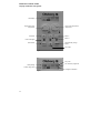
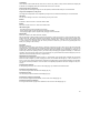
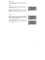
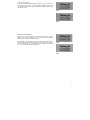
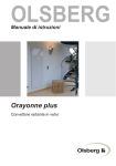
OLSBERG
User Manual
OLSBERG
Standard heater CTSC
Inhaltsübersicht
Table of Contents
Allgemeines.................................................................. 6
Anlieferungszustand, Verpackung, Recycling......... 6
General .......................................................................22
Delivery, Packaging, Recycling..............................22
Bedienung .................................................................... 7
Wärmespeicherung .................................................. 7
Handsteuerung......................................................... 7
Wärmeentnahme...................................................... 7
Sommerbetrieb......................................................... 7
Energiespartipps ...................................................... 7
Operation ....................................................................23
Heat Storage...........................................................23
Manual Control........................................................23
Heat Discharge .......................................................23
Summer Operation .................................................23
Energy Saving Tips.................................................23
Elektronische Regelung CTSC.................................... 8
Anzeige und Tastenbelegung .................................. 8
Standardanzeige .................................................... 10
Ladung.................................................................... 10
Entladung ............................................................... 10
Kindersicherung ..................................................... 10
Menüauswahl ......................................................... 11
Wochentag / Uhrzeit ........................................... 11
Fehler löschen .................................................... 11
Auswahl Untermenü............................................... 12
Sprachauswahl ................................................... 12
Ventilatorfreigabe Programm ............................. 13
Reduzierte Raumtemperatur.............................. 15
Ladegradabsenkung........................................... 16
Programm löschen ............................................. 17
Electronic control CTSC.............................................24
Display and button arrangement ............................24
Standard display .....................................................26
Charging..................................................................26
Discharging .............................................................26
Child-proofing..........................................................26
Menu selection........................................................27
Day / time ............................................................27
Deleting errors.....................................................27
Submenu selection .................................................28
Language selection.............................................28
Fan clearance programme..................................29
Reduced room temperature................................31
Charge level reduction........................................32
Programme deletion............................................33
Wartung und Pflege ................................................... 18
Care and Maintenance...............................................34
Ersatz-Filterset ........................................................... 18
Spare filter set ............................................................34
Zu beachtende Hinweise ........................................... 18
Important Instructions.................................................34
Störungen................................................................... 19
Fehlermeldungen ................................................... 19
Defects........................................................................35
Error messages ......................................................35
Technische Daten ...................................................... 20
Technical Data............................................................36
Allgemeine Garantiebedingungen ............................. 21
General guarantee conditions....................................37
3
Electronic control CTSC
Display and button arrangement
LCD-display
Target room temperature,
rotary button
Target charge level,
rotary button
Button -
OK button
Button +
LED control lights
Supplementary charge
button
Menu button
Fan button
Fig.1
Day / time
Fan clearance programme
Child-proofing
Current charge level
Charge level reduction
Fig.1a
24
LCD display
This is used to communicate with the control unit. As soon as any button or rotary knob is activated, the display will
be backlit. The backlighting will be de-activated if idle for around 15 seconds.
Target charge level, rotary knob
By turning the knob the target charge level can be adjusted; it will be stored directly as a control variable.
Target room temperature, rotary knob
The target room temperature can be adjusted by turning the knob; it will be stored directly as a control variable.
OK button
For use when entering a menu item and confirming an entry in the menu.
Button +
Increases a value in the menu. That value will then flash.
Button Decreases a value in the menu. That value will then flash.
LED control lights
- Red (left), lights up when the appliance is charging.
- Green (centre), lights up when fan clearance has been activated.
- Orange (right), lights up when supplementary charging has been activated.
Menu button
Menu item selection (see “Menu selection” chapter)
Die The procedure is always identical. Use the menu button to select a menu item. In order to edit this menu item,
confirm using ‘OK’. Then either a dialogue box will appear, showing which button should be used to activate which
function, or you will be taken directly to a display showing a flashing value. A flashing value can be changed using
+/-; this must then be confirmed using ‘OK’. Once you are in a menu item, you can exit it by pressing the menu
button (or by waiting for 30 seconds).
Fan button
Manual fan clearance
The electronic control system must receive a clearance message for the fan to start. This can be issued manually
using this button, or automatically by programming switch points (see chapter on “Fan programme”). If you use the
manual option, please remember that the fan clearance will remain activated until you deactivate it. Therefore, you
should only choose this operating mode if you intend mainly discharging the appliance statically (i.e. without fan
operation), and only intend to switch on the fan occasionally. The green LED above the button will light up once fan
clearance has been activated (manually or programmed).
Supplementary charge button
This button is used to activate a daytime charge (i.e. at peak rates). Once this has been activated, the orange LED
above the button will light up. Since charging is involved, the red LED will also light up. After a maximum of 2
hours, or once a 35% charge level has been reached, the supplementary charge will automatically be de-activated.
This function has been provided in case more heat is unexpectedly required than had been charged on the previous day.
Indication Child-proofing
If child-proofing is active, it can be seen in the display (Fig.1a). All buttons are without function.
Indication Current charge level
The current charge level is indicated in the display (Fig.1a).
Indication Day / time
The actual day and time is indicated in the display (Fig.1a).
Indication Fan clearance programme
If a fan clearance programme is activated, it can be seen in the display (Fig.1a).
Indication Charge level reduction
If a charge level reduction programme is activated, it can be seen in the display (Fig.1a).
25
Standard display
The standard display shows the following:
Day of the week, time and current charge level (calculated using the core sensor). The more heat has been
stored, the more black will show in the bar (in this
case 0%).As soon as any button or rotary knob is
activated, the display will be backlit. If you want to
backlight the standard display, press the OK, + or –
buttons, since these do not directly execute an action.
The backlighting will be deactivated if the display is
idle for around 15 seconds
Day / time
Current
charge level
Fig.2
Charging
By turning the left-hand rotary knob (target charge
level), the target charge level can be changed. It will
then be stored as the new control variable. The display utilises a bar (0 to 100%) in the LCD display. To
help orientate the user, the bar is marked every 25%.
Bar display
Target value
Charge level
Rotary button
Target
charge level
Fig.3
Symbol
Charge level
Discharging
By turning the right-hand rotary knob (target room
temperature), the target room temperature can be
changed. It will then be stored as the new control
variable. Settings of between 5°C and 30°C are available and will be shown in the LCD display.
Display
Target value
Room
temperature
Rotary button
Target room
temperature
Fig.4
Child-proofing
To avoid settings on the storage unit being accidentally changed (when cleaning, or by children playing),
you can activate the child-proofing device.
If you press the OK button for 4 seconds, the ‘Button
lock’ indicator will appear at the top left of the display.
This setting means that the control unit will not execute any manual functions. Neither the buttons nor
the rotary knobs will be active. If it is necessary to
readjust the rotary knobs while the buttons are locked,
and the lock is de-activated, the control unit will naturally accept the new values. However, this will also be
shown immediately. This means that, once the lock
has been deactivated (by pressing the OK button for 4
seconds), the adjusted value (e.g. room temperature
30°C) will be displayed. If a rotary button has not been
adjusted, you will only see the ‘Button lock’ message.
26
Fig.5
Symbol
Room
temperature
Menu selection
Using the menu button, the following two menu items can be selected.
You can exit a selected menu item by pressing the menu button, or by
waiting for around 30 seconds.
Day / time
The correct time must be set in order to avail of off-peak rates. Correct day
and time settings are also important for the fan clearance programme and
charge level reduction programme.
In order to change the day and the time, use ‘OK’ to confirm the day/time
menu item.
The day will flash first; this can be changed using the + or – button. Once
confirmed using ‘OK’, the display will show the time. Here, too, you can
use the + or – button to set the hours and minutes. Use ‘OK’ to confirm the
required value.
Fig.6 Day / time
Deleting errors
If faults occur in respect of the control unit, these will be shown in the LCD
display, alternating with the standard display. In addition, the backlighting
facility will be activated to alert the operator to the error. Since a permanently backlit LCD display can be obtrusive, the ‘Error deletion’ function
allows you to switch the backlighting facility off.
In order to cancel the backlighting in the event of an error message, use
‘OK’ to call up the Error Deletion menu item. The display “Delete Error OK”
will appear for confirmation (Fig.8).
Fig.7 Deleting errors
Important: The error message will only cease once the error has been
rectified.
Fig.8
27
Submenu selection
Press the menu button for 4 seconds to additionally open the following five
menu items in succession. Confirm one of the menu items with "OK" to
open this menu item. You can exit a selected menu item by pressing the
menu button, or by waiting for 30 seconds.
Language selection
Various languages can be stored to facilitate the dialogue between the
user and the CTSC control unit. You can choose between English, German, French, Dutch and Spanish. The menu text will be displayed in the
various languages by turns.
In order to change the language, use ‘OK’ to confirm the Language Selection menu item. The setting to be changed will flash. You can select the
various languages using + or – . In order to activate the language in question, confirm again using ‘OK’. The selected language will then be stored.
Display
Change
Charge
Del
Delete
EN
Error
Fan
Fr
Language
Mo
New
No
Off
OK
On
Pres
Program
reduced
Sa
Su
Th
Tu
We
Yes
Table 1
28
Meaning
Change
Charge
Delete
Delete
English
Error
Fan
Friday
Language
Monday
New
No
Off
OK
On
Preselect
Program
reduced
Saturday
Sunday
Thursday
Tuesday
Wednesday
Yes
Fig.9
Fan clearance programme
You can use the fan programme to define the periods (days and times)
when the fan can be started if needed. A total of 42 switchpoints are available for definition. This means that there are three different activation and
deactivation points for each day of the week. In order to save energy, it
makes sense to define activation and deactivation points for the periods
when you require the fan to dissipate heat.
However, this programme will not switch the fan on: it merely allows it to
be switched on once the current room temperature is lower than the target
room temperature. The fan cannot start during periods which have not
been specified. During such periods, it is only possible to discharge the
appliance statically (via the appliance surfaces).
The same function can be executed using the fan button. In that case,
however, it must be manually activated and deactivated. If a programme
has been stored, you can use the fan button to override the switchpoints.
This means that, if fan clearance has been issued by the programme but
you do not wish the fan to be activated, you can use the button to deactivate the fan clearance. The programme will reassume control at the next
programmed switchpoint.
Fig.10
Once you have selected the fan programme (Fig.10) using ‘OK’, you have
three options (Fig.11):
a) By pressing ‘OK’, you can change a switchpoint, add new ones or delete existing ones: this means you can freely define the switchpoints.
b) By pressing + you can select one of the preselection programmes (see
Table 2, “Fan clearance, preselection programme”). You can adapt
these to individual user requirements using the menu item “OK =
Change”, mentioned above.
Fig.11
c) By pressing – you can restore the fan menu's factory setting. This
means that both user-defined switchpoints and preselection programmes will be deleted. If you have selected a preselection programme, and wish to store another programme, you do not need to delete the first programme. You can load another programme directly
over it. Deletion is only necessary if you do not require any switchpoints.
An activated fan clearance program is indicated in the standard display by
the square in the right top under the minute display (Fig.12 + Fig.1a).
Fig.12
a) Defining switchpoints
If you have selected Point a) by pressing the ‘OK’ button (Fig.13), the first
switchpoint will appear automatically (but this switchpoint does not have
any function, since it switches off the fan clearance, and this does not take
place on a weekday). In order to activate it, go to “Off”, confirm using ‘OK’,
and use + to change the button to “On” or „Red“ (see chapter „Reduced
room temperature“). Then use OK to call up the time, which you can confirm using the + and – buttons. Further activation of the ‘OK’ button will call
up the days of the week, which you can activate using the + button or deactivate using the - button.
Fig.13
Once you have defined this switchpoint, and have ceased switchpoint
definition, the fan clearance will be active until the next day on which the
fan has not been cleared.
If you wish to define another switchpoint, proceed as follows:
29
Whenever you wish to define a new switchpoint, you must display switchpoint 1 (flashing, Fig.14) and then use the – button to call up a new
switchpoint (Fig.15). After inputting the time, the switchpoint number will
be automatically assigned, and will be incorporated into the existing number sequence based on ascending time.
Thus, if you have called up a new switchpoint (Fig.15) and confirmed it
using ‘OK’, you can define the switch status (On/Off/Red/Del), the time
and the days as described above. Repeat the procedure until all required
switchpoints have been inputted.
Fig.14
Once you have defined one or more switchpoints, you can delete any
switchpoint by calling it up and using ‘OK’ to go to the switch status
(On/Off/Red). You can then use the – button to set it to “Del”, and delete it
by pressing ‘OK’.
Fig.15
b) Selecting preselection programmes
If you wish to define several switchpoints, it is always advisable to first
select a programme which most closely approximates to user requirements (see Table 2, “Fan clearance, preselection programmes”), and then
to adapt this programme to your requirements as shown above.
Fig.16
Select a preselection programme by using the + (= Pres) button (Fig.16).
You can now use the + or – button to select one of the 5 preselection programmes (Fig.17), confirming your selection with ‘OK’.
If you want to accept the programme as shown, use ‘Menu’ to exit it.
If you want to change the programme, use ‘OK’ to access the switchpoints
and change them as described above.
Fig.17
Program
Pres 1
Switchpoint 1
Switchpoint 2
Pres 2
Switchpoint 1
Switchpoint 2
Switchpoint 3
Switchpoint 4
Pres 3
Switchpoint 1
Switchpoint 2
Switchpoint 3
Switchpoint 4
Pres 4
Switchpoint 1
Switchpoint 2
Pres 5
Switchpoint 1
Switchpoint 2
Switchpoint 3
Switchpoint 4
Switch status
Time
Su
Mo
Tu
We
Th
Fr
Sa
Comment
On
Off
06:00
22:00
x
x
x
x
x
x
x
x
x
x
x
x
x
x
Standard
On
Off
On
Off
06:00
08:00
17:00
22:00
x
x
x
x
x
x
x
x
x
x
x
x
x
x
x
x
x
x
x
x
x
x
The room is not used
during working hours
(Mo–Fr)
On
Off
On
Off
06:00
08:00
17:00
22:00
x
x
x
x
x
x
x
x
x
x
x
x
x
x
x
x
x
x
x
x
x
x
x
x
x
On
Off
07:00
19:00
x
x
x
x
x
x
x
x
x
x
On
On
Off
Off
09:00
17:00
19:00
23:00
x
x
x
x
x
x
The room is not used
during working hours
(Mo–Sa)
Office
(not used on weekends)
x
Table 2 Fan clearance, preselection programmes
30
x
x
Weekend home
(used from Fr–Sa)
c) Delete fan programme
Once you have defined switchpoints (using ‘OK’ or +, Fig.18) and wish to
reverse them, you can use – to access switchpoint deletion, and then use
‘OK’ (Fig.19) to restore the factory setting for the ventilator clearance programme menu item.
Fig.18
Fig.19
Reduced room temperature
Because the set room temperature is not always practical as a control
variable, (e.g. for night lowering), under this menu item it is possible to
define a reduced room temperature (Fig. 20).
If the reduction has been selected in the fan clearance program (Fig. 21)
then the system will be regulated to the value that is set here, e.g. to 18°C
room temperature (Fig. 21). It is possible to select a target value between
5°C – 20°C for the reduced room temperature.
Fig.20
Fig.21
31
Charge level reduction
In addition to fan clearance times, you can also define specific charge
level reductions (Fig. 22). This makes sense if you require less heat on
specific and recurring days of the weeks, for example if you are never
home at the weekends (so that your home requires less heating), or if you
have a weekend home which only requires heavier heating from Fridays to
Sundays. In that event, you can set the target charge level rotary knob to
the required charge level, and use this programme to set a percentage
reduction for those days when less heat is required.
Fig.22
Here, too, you have three selection options (Fig. 23):
a) You can carry out settings manually by pressing ‘OK’. The 'Day' menu
item, and the associated charge level reduction, will appear (Fig. 24).
You can set the day using the + or – buttons, confirm using ‘OK’, and
then define the associated charge level reduction using + or – (from 0
to 70%). Confirm this pair of values using ‘OK’. You can then define further days of the week and the associated reductions.
Fig.23
b) You can select the menu item “Preselection, charge reduced programme” by pressing + (Fig.25), and you can then use the + or – button to select a programme (see Table 3, “Programmes, charge reduce
preselection”). You can adapt these to individual user requirements using the menu item “OK = Change”, described above.
c) By pressing – you can restore the charge reduced menu's factory setting. This means that both user-defined reductions and preselection
programmes will be deleted.
Once you have defined the reductions (using ‘OK’ or +, Fig. 23) and
wish to reverse them, you can use – to access reduction deletion, and
then use ‘OK’ (Fig. 26) to restore the factory setting for the charge reduced programme menu item.
Fig.24
Fig.25
Important!
The charge reduction always relates to the value set using the target
charge level rotary knob. This means that if you set a charge of 75% (third
bar section) at the control unit, and specify a charge reduction of 20% for
one day, the charge will be 60% during the night preceding that day.
Fig.26
Calculation aid:
Target charge level set - (target charge level set x charge level reduction/100) = reduced charge level
I.e. in respect of the example above: 75 - (75 x 20/100) = 60%
Program
Pres 1
Pres 2
Pres 3
Pres 4
Pres 5
So Mo
Tu We Th
Fr
Sa
0% 0% 0% 0% 0% 0% 0%
0% 30% 30% 30% 30% 30% 0%
0% 30% 30% 30% 30% 30% 30%
70% 0% 0% 0% 0% 0% 70%
0% 70% 70% 70% 70% 30% 0%
Comment
Standard
The room is not used during working hours (Mo-Fr)
The room is not used during working hours (Mo-Sa)
Office (not used on weekends)
Weekend home (used from Fr-Sa)
Table 3 Charge level reduction, preselection programmes
An activated charge level reduction program is indicated in the standard
display by the square in the bottom right under the minute display (Fig.27
+ Fig.1a).
Fig.27
32
Programme deletion
You can use this menu item to delete all user-defined values and programmes, thus globally restoring the factory settings for all menu items.
Use the OK button to access the Programme Deletion menu item (Fig.28).
You can use the + button to activate the factory setting, while pressing the
- button exits the menu item without making any changes (Fig.29). ‘OK’ will
appear in the display to confirm that the factory setting has been activated
(Fig.30).
Fig.28
Fig.29
Fig.30
33
Care and Maintenance
Spare filter set
• Olsberg heaters have been constructed so that
they need only a minimum of maintenance.
The spare filter set contains 5 fluff filters as replacements,
2 – 4kW: No. 14/5121.9299
5 – 7kW: No. 14/5161.9299
• Olsberg-Heaters are fitted with a fluff filter. The fluff
filter should be cleaned at regular intervals, dependent on the amount of dust in the room (ideally
before each heating season).
Cleaning the filter should only take place on a cold
heater. Push the air-outlet grille to the left. The fluff
filter can now be removed and cleaned or replaced
by a new one (see chapter „Spare filter set“).
Caution: The fluff filter must be completely dry before it is reinstalled into the heater.
Important Instructions
• As the surfaces of the heater cabinet get hot in
use, flammable or other objects presenting a danger of fire must not be placed on, or near the
heater.
Do not, therefore, place any wooden objects,
clothes or washing, newspapers, blankets or the
like on or over the heater and do not put any
pieces of furniture made of inflammable materials,
nor spray tubes or similar objects closer than
25cm in front of, or on the heater, especially not in
front of the air-outlet grille.
• It is important to remember that the surfaces of
the heater can reach temperatures in excess of
80°C during operation.
Fig.31 Fluff filter
• The fan is equipped with self-lubricating bearings.
We recommend that the heater be opened from
time to time by a qualified installer who can free
the heater from any dust which may have accumulated on the fan or in the air-outlet channels.
• Cleaning and maintenance intervals are dependent
on the conditions under which the heater works.
We recommend that the first check take place at
the latest before the beginning of the second heating period. Further maintenance intervals can then
be individually set.
• We recommend that the control and regulation
elements of the heater also be checked regularly.
All safety, control and regulation elements should
be checked by a qualified installer at the latest 10
years after initial installation. This can save unnecessary energy costs.
• Do not use soft-scrub or other abrasive substances
to clean the surfaces of the heater. Normal household cleaners suffice entirely.
34
• The storage heater is only to be used in rooms
where neither explosive gases (e.g. from floorsealant), nor inflammable dust is present!
If renovation work causing dust accumulations is
taking place the heaters must either be operated
without the fans or switched off altogether.
• Electrical appliances conform to valid safety regulations. Repairs and service to electrical appliances
must only be carried out by a competent electrician. Improper repair can mean distinct danger to
the user.
• This heater is not intended for operating by per-
sons (including children), with reduced physical,
sensory or mental abilities or for lack of experience
and/or for lack of knowledge to be used it by a person responsible for their security is supervised or
received from instructions like the heater to use.
Children should be supervised, in order to guarantee that they do not play with the heater.
Defects
If your storage heater malfunctions, and the display does not show any
error messages, please first check the following:
• Appliance failed to charge:
- If the target charge level rotary knob on the appliance set to zero?
- Are the fuses on the current distribution board loose or defective?
• Appliance fails to discharge via the fan:
- Has the temperature shown on the display been set using the target
room temperature rotary knob to a lower value than the current room
temperature?
- Has the fan been cleared? If the green LED control light is not on, the
fan has not been cleared.
- Are the fuses for the fan circuit on the current distribution board loose
or defective?
Error messages
Faults caused by the electronic control system will be shown in the LCD
display, alternating with the standard display (fig.32). In addition, the backlighting facility will be activated to alert the operator to the error..
The following error messages may be displayed:
Fig.32
Display
Description
Error 1
Error when measuring the room temperature;
room temperature sensor or its cable defective
Error 2
Error when measuring the core temperature;
core sensor or its cable defective
Error 3
Defective charge process;
core temperature too low at the end of the charge process,
or fell too steeply during charging
Error 5
Temperature on the control module or
operating element too high
Error 7
Clock not OK
Error 8
Internal error in the control unit
Error 9
Internal error in the operating element
1)
Table 4
1)
The error detection setting in respect of the time is highly sensitive, which means that even very minor irregularities may result in an error message. Before calling customer service, access the Day/Time menu and set the
time. Only if this error message recurs repeatedly is the error serious enough to call customer service.
Your fitter will naturally be available to assist you in the event of faults.
35
36
Heating elements
(W)
3 x 670
3 x 1000
3 x 1335
3 x 1670
3 x 2000
3 x 2335
Type
14/522
14/523
14/524
14/525
14/526
14/527
Technical Data
7,0
6,0
5,0
4,0
3,0
2,0
Rating
(kW)
56
48
40
32
24
16
Storage Capacity
(kWh)
Voltage
3/N/PE~400V
140
640 x 750 x 270
640 x 1310 x 270
640 x 1310 x 270
640 x 1135 x 270
347
265
225
180
100
640 x 575 x 270
640 x 925 x 270
Weight
(kg)
Dimensions
H x W x D mm
6xSP29 / 6xSP40
6xSP19 / 6xSP39
5xSP19 / 5xSP39
4xSP19 / 4xSP39
3xSP19 / 3xSP39
2xSP19 / 2xSP39
Core-brick packs
General guarantee conditions
Dear customer,
in guarantee case the country specified rights are valid which you may claim directly towards your dealer.
37
olsberg.com
88
10/2009
Hüttenstraße 38
59939 Olsberg
T +49 2962 805-0
F +49 2962 805-180
[email protected]
1) 78/4614.5202
Olsberg GmbH