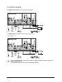
1
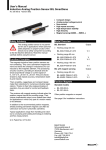
Technical Manual
Cam – Controller
BDD-CC 08-1-P
BDD-CC 08-1-SSD
1. General.............................................................................................................................................. 1
2. 2. Front Panel / Keyboard ................................................................................................................ 2
3. Specification of Operation Modes .................................................................................................. 3
3.1 Position and Program Number ............................................................................................................................ 3
3.2 Selecting Programs Number with Keyboard........................................................................................................ 3
3.3 Cam Programming............................................................................................................................................... 4
3.3.1 Input Cam Program
5
3.3.2 Switchpoint Types
6
3.3.3 Delete Cam Program
7
3.3.4 Remove Switchpoints
7
3.4 Deadtime Compensation (dynamic cams)........................................................................................................... 8
3.5 Entering Parameter.............................................................................................................................................. 8
3.5.1 Control Parameters
9
3.5.2 Encoder Parameters
11
3.5.3 Hysteresis after change in direction
11
4. External Function Selection .......................................................................................................... 12
4.1 Function " Select Program "............................................................................................................................... 12
4.2 Function "Lock Outputs" .................................................................................................................................... 12
4.3 Function "Keyboard Enable".............................................................................................................................. 12
4.4 Function "Zero Set" resp. "Preset"..................................................................................................................... 12
4.5 Function "Teach-In" ........................................................................................................................................... 12
5. Test Mode ....................................................................................................................................... 13
6. Initial Start-Up................................................................................................................................. 14
7. Codes for Operation Mode ............................................................................................................ 15
8. Error Messages and Error Elimination......................................................................................... 15
9. Technical Data................................................................................................................................ 16
10. Connection diagram..................................................................................................................... 17
10.1 BDD-CC 08-1-SSD for absolute SSD Feedback System................................................................................ 17
10.2 BDD-CC 08-1-P for absolute Transducer with P-Interface.............................................................................. 17
11. Precautions................................................................................................................................... 18
12. Ordering Code .............................................................................................................................. 18
II
User's Manual BDD-CC 08-... Cam Controller
1. General
The BDD-CC 08-... is a modern programmable cam controller for linear or rotary (0 – 360°) position feedback.
The unit is packaged in a compact, standard housing for easy panel mount.
A large LED display and numeric keyboard provide for quick and simple operation. Codes and the input signal
"key switch" assure protection against use by unauthorized personnel.
The BDD-CC 08-... is available for the following feedback systems:
- Absolute encoder with SSD-interface
- Absolute transsonar encoder (P-interface)
The BDD-CC 08-... can be used as:
- rotary programmable cam controller (0 – 360°)
- linear programmable cam controller (displacement)
Cam functions:
- Static and dynamic cams with dead time compensation
- Direction-dependent cam
- Multiple switchpoints for each cam
- 300 switchpoints can be distributed over 15 programs
- Tool/zero point correction for each separate program
- 8 outputs / cams
- 16 or 24 outputs cams possible by using parallel versions of the BDD-CC 08-...
Additional functions (using keyboard):
- Display program number
- Select program number
- Test mode
Additional functions (using external 24 V inputs):
- Program select
- Teach-In (take over displayed position directly in program mode)
- Lock outputs
- Keyboard enable
- Zero set
The BDD-CC 08-... is ideal for fast running machines due to its fast cycle time (see Technical Data).
!
Wiring and startup of this device may be done by trained personnel only. Read this manual
carefully. Note the installation instruction and the initial startup. Non-attention of the instructions
will result in loss of warranty and liability on the part of the manufacturer.
This unit monitors operation conditions internal to the unit as well as on the equipment side.
Malfunctions caused by defective elements cannot however prevent.
An emergency stop switch on the equipment side must therefore be installed to prevent personal
injury.
User's Manual BDD-CC 08-... Cam Controller
1
2. 2. Front Panel / Keyboard
LED display for programming and displaying the actual position.
Status display of output 2 are active.
1
2
3
4
5
6
Z
@
M
i
o
oM
2
7
8
Numeric keyboard.
Clear key to delete input values.
Memory key for save values.
Cam programming: switchpoint "On".
Cam programming: switchpoint "Off".
Press both at the same time:
Select programming mode or quit. With an additional code input, select parameter list.
The display flashes if during a programming sequence no key has been pressed within 60 seconds.
pressing any key will stop the display from flashing.
User's Manual BDD-CC 08-... Cam Controller
3. Specification of Operation Modes
3.1 Position and Program Number
In standard operation mode, the actual position of the feedback system is displayed, and the LED's indicate which
outputs are active.
Actual position, e.g. 120.0 mm or 120.0°
Outputs 2, 3, 5 are "on", the other outputs are "off".
1
2
3
4
5
6
7
8
M
1
2
3
4
5
6
7
After pressing, the actual program number is displayed.
8
For rotary applications, the display changes the units at speed higher than 10 rpm from position in degrees to
speed in rpm.
Actual speed in rpm
1
2
3
4
5
6
7
8
3.2 Selecting Programs Number with Keyboard
Activate input signal "keyboard release" !
1
1
2
2
3
3
4
4
5
5
6
6
7
7
oM
M
Select code mode.
ZM
Input program number and confirm.
oM
Quit programming mode. Active new program.
Confirm without code.
8
8
This function is only possible, if the 4 input signals for external program select are at "0 Volt" or not
connected (see 4.1 for additional information)
User's Manual BDD-CC 08-... Cam Controller
3
3.3 Cam Programming
300 switchpoints can be distributed over 15 programs.
If many switchpoints are required, the number of programs must be reduced.
Example:
4 programs = 75 switchpoints per program
15 programs = 20 switchpoints per program
Before programming, set the control parameter P6 "number of programs" (see 3.5.1).
Programming Example:
Program No:
Switchpoint
Output No.
Position
Function
SP 1
Out 3
50,0
ON
SP 2
Out 3
115,5
OFF
SP 3
Out 1
70,0
ON
SP 4
Out 1
130,0
OFF
SP 5
Out 1
210,0
ON
SP 6
Out 1
320,0
OFF
Pro 12
|
|
SP 20
|
Out 7
275,0
|
OFF
Example:
Out 1
Out 3
50
70
115,5
210
130
4
After changing the travel direction, the switchpoints will switch after leaving
the hysteresis (P90)
User's Manual BDD-CC 08-... Cam Controller
3.3.1 Input Cam Program
Activate input signal "keyboard enable" !
1
1
1
1
1
1
1
1
2
2
2
2
2
2
2
2
3
3
3
3
3
3
3
3
4
4
4
4
4
4
4
4
!
5
5
5
5
5
5
5
5
6
6
6
6
6
6
6
6
7
7
7
7
7
7
7
7
oM
M
Select program mode.
ZM
Enter program number and confirm.
ZM
If required, enter the zero point offset of the selected program and
confirm.
ZM
Enter switchpoint and confirm, or confirm the indicated switchpoint.
ZM
Enter output number (1 - 8) and confirm.
0 = switchpoint turned off.
ZM
Enter switchpoint position and confirm.
io
M
Select function (on/off) and save.
ZM
Enter next switchpoint.....
oM
Quit programming mode.
Confirm without code.
8
The LED's indicate which outputs are already programmed.
8
8
8
8
LED of the selected output flashes.
8
8
LED of the selected output flashes.
Description of function see 3.3.2.
8
After quitting the programming mode, the switchpoints will be recalculated in the unit. During
this time, the output signals and the signal "ready" are "off" for a short time.
User's Manual BDD-CC 08-... Cam Controller
5
3.3.2 Switchpoint Types
Switchpoints not direction dependent:
Switchpoint is turned off.
no effect
Start of cam:
Switchpoint is "on" at higher positions,
otherwise "off".
End of cam:
Switchpoint is "off" at higher positions,
otherwise "on".
Direction dependent switchpoints:
Output switches "on" by positive
direction (low -> high)
Output switches "off" by positive
direction (low -> high)
Output switches "on" by negative
direction (high -> low)
Output switches "off" by negative
direction (high -> low)
6
User's Manual BDD-CC 08-... Cam Controller
3.3.3 Delete Cam Program
Activate input "keyboard enable" !
1
1
2
2
3
3
4
4
5
5
6
6
7
7
oM
M
Select program mode.
Z
Enter program number.
@
Hold key down at least 3 seconds, until "CLr" is displayed.
Confirm without code.
8
8
Selected program is deleted.
1
2
3
4
5
6
7
8
Delete function ended.
1
2
3
4
5
6
7
8
3.3.4 Remove Switchpoints
Activate input "keyboard enable" !
1
1
1
2
2
2
3
3
3
4
4
4
5
5
5
6
6
6
7
7
7
oM
M
Select program mode.
ZM
Enter program number and confirm.
Z
Enter switchpoint number.
@
Hold key down at least 3 seconds, until "CLr" is displayed.
Confirm without code.
8
8
8
Selected switchpoint is removed.
1
2
3
4
5
6
7
8
Delete function ended.
1
2
3
4
5
6
7
8
User's Manual BDD-CC 08-... Cam Controller
7
3.4 Deadtime Compensation (dynamic cams)
A separate deadtime can be given to each output signal. The corresponding code is used for entering the
deadtime compensation.
Activate input "keyboard enable" !
1
1
1
1
2
2
2
2
3
3
3
3
4
4
4
4
5
5
5
5
6
6
6
6
7
7
7
7
oM
ZM
Select code mode.
ZM
Enter deadtime for output 1 and confirm. Input range (0-250 ms)
ZM
Enter deadtime for output 2 and confirm. Input range (0-250 ms)
ZM
Enter deadtime for output 3...
Enter code for parameter "deadtime compensation" and confirm.
8
LED of selected output flashes.
8
LED of selected output flashes.
8
8
3.5 Entering Parameter
In the programming mode and an additional code input, the BDD-CC 08-... can be set up for a special application.
Choose directly between Control parameter and Sensor parameter by using the corresponding code (see 11.).
Activate input "keyboard enable"!
1
2
3
4
!
8
5
6
7
oM
ZM
Select code mode.
M
oM
Save changes and switches to next parameter.
Enter code for selected parameter (see 11.) and confirm.
8
Quit parameter mode.
After quitting parameter mode, the switchpoints are recalculated. During this time the output
signals and the signal "ready" are "off" for a short time.
User's Manual BDD-CC 08-... Cam Controller
3.5.1 Control Parameters
No.
Description
Default
P0
Rotary / Linear
0: Rotary (units in degrees)
1: Linear
1
P1
Digits after decimal point for P2 scaling (only for linear feedback systems)
Range: 0-5
3
P2
Scaling (for display)
Rotary: steps per 360 degrees, degree display
Range: 1-999999
Your setting
Linear: Steps per required unit (e.g. mm, inch,...)
Range (depends on P1): 0.000001-999999
SSD feedback system:
Transsonar feedback system (P-interface):
1
21
P3
Setting decimal point
Displayed digits after decimal point (0-3)
0
P4
Feedback direction (or direction of rotation)
0: normal
1: inverted
0
P5
Power-up condition of directional cams:
(before a movement takes place)
0: Start condition "Off"
1: All "L-H" switchpoints under the turn-on position
are switched.
2: All "H-L" switchpoints over the turn-on position are
switched.
0
P6
Number of programs (1 -15)
The number of programs determines the distribution of the 300
switchpoints.
4
e.g.
!
4 Programs = 75 switchpoints per program
15 Programs = 20 switchpoints per program
Check the program again after changing parameters P3 or P6.
User's Manual BDD-CC 08-... Cam Controller
9
3.5.1.1 Calculation of the Scaling (Parameter P2)
Rotary applications
Scaling is entered in steps / 360 degree rotation
Linear application with encoder
Example: Spindle drive with (rotary) encoder resolution 4096 steps/revolution. The position of the carriage
needs to be displayed.
a:
Display in "inches", spindle with 0.5 inch pitch
4096 steps (1 spindle revolution) corresponds to 0.5 inches travel
P2 = 4096 steps / 0.5 inch = 8192 steps/inch.
b:
Display in "millimeters", spindle with 10 mm pitch
4096 steps (1 spindle revolution) corresponds to 10 mm travel
P2 = 4096 steps / 10 mm = 409.6 steps/mm
Linear application with magnetostrictive transducer
10
a:
Display in "inch":
P2 = (60000 / waveguide gradient [m/s] ) x 25.4
(Check: P2 = ca. 533.4 steps/inch)
b:
Display in "millimeter":
P2 = 60000 / waveguide gradient [m/s] (see transducer label)
(Check: P2 = ca. 21.000 steps/mm)
User's Manual BDD-CC 08-... Cam Controller
3.5.2 Encoder Parameters
For BDD-CC 08-1-SSD device feedback only
No.
Description
Default
P21
Setting zero point (zero offset)
(Enter value in required units, e.g. mm)
Range: -9999.99 - +9999.99
0.00
P22
Mode:
0: Standard (BDD-CC 08-... as master module)
1: Parallel (BDD-CC 08-... as salve module)
0
P23
SSD-device: number of revolutions
"4096" for linear feedback systems
Range: 1 (Single-Turn) – 8192
4096
P24
SSD-devices: number of steps per revolution
"4096" for linear systems:
Range: 4 – 524288
4096
P25
SSD-device data format
0: Gray code
1: Binary code
0
Your setting
For BDD-CC 08-1-P device feedback only
No.
Description
Default
P41
Setting zero point (zero offset)
(value in desired units, e.g. mm)
Range: -9999.99 - +9999.99
0.00
P42
Mode
0: Standard (BDD-CC 08-... as master module)
1: Parallel (BDD-CC 08-... as slave module)
0
Your setting
3.5.3 Hysteresis after change in direction
No.
Description
Default
P90
Hysteresis (Enter value in desired units, e.g. mm)
Range: 0 - +999.999
1.000
User's Manual BDD-CC 08-... Cam Controller
Your setting
11
4. External Function Selection
4.1 Function " Select Program "
The 4 input signals (Terminals X1.1 - X1.4) can be used to select a saved program externally. See following table
for program selection (0=0 V, 1=24 V):
Prg-Select 1
Prg- Select 2
Prg- Select 4
Prg- Select 8
0
0
0
0
1
0
0
0
0
1
0
0
1
1
0
0
0
0
1
0
1
0
1
0
0
1
1
0
1
1
1
0
0
0
0
1
1
0
0
1
0
1
0
1
1
1
0
1
0
0
1
1
1
0
1
1
0
1
1
1
1
1
1
1
Program-No
-
1
2
3
4
5
6
7
8
9
10
11
12
13
14
15
!
If these input signals are all at "0", program selection may be done manually using the keyboard.
When changing programs, the switchpoints are recalculated. During this time the output signals
and the signal "ready" are "off" for a short time.
The program change has priority in all operation modes.
4.2 Function "Lock Outputs"
A +24 V signal on input signal "lock outputs" (pin X1.6) switches all output signals and the signal "ready" to "off".
4.3 Function "Keyboard Enable"
A +24 V signal on input signal "keyboard enable" (pin X1.7) allows to enter program or parameters from keyboard.
However, error confirmation and displaying program number is always possible.
Example application: Locking by key switch.
4.4 Function "Zero Set" resp. "Preset"
A +24 V pulse (positive edge) on input pin X1.8 sets the actual displayed position to zero. The internal calculated
zero offset is saved in P21 resp. P41.
4.5 Function "Teach-In"
With a +24 V pulse (positive edge) on input pin X1.5 it is possible to set the switchpoint positions or the zero point
offset by the actual position.
Example application: Moving the machine to the desired switchpoint, and set the switch point directly.
12
User's Manual BDD-CC 08-... Cam Controller
5. Test Mode
For initial start-up or error seeking the input signals can be displayed and the output signals can be set and
deleted individually. The output signal "ready" can also be switched.
In test mode the normal functions are switched off.
During the test mode the outputs are switched off. By manual switching the outputs or the signal
"ready", the machine could be caused to move. It is therefore recommended to lock out, power
down or otherwise disable the machine during test mode.
!
oM
ZM
1
2
3
4
5
6
7
Select code mode.
Enter code for "Test Mode" (see 11.) and confirm.
8
The corresponding LED's display the input signals which
have +24 V
1
2
3
4
5
6
7
8
M
Z
1
2
3
4
5
6
7
Toggle between displaying input and output signals.
Enter the output number and the corresponding output switches
"on" or "off".
The LED's indicate the corresponding condition.
8
oi
oM
User's Manual BDD-CC 08-... Cam Controller
Turn on/off the output signal "ready".
Quit test mode.
13
6. Initial Start-Up
The initial start-up for the first time is performed as follow:
1.
Connect power supply (but do not turn on yet).
Connect transducer or encoder.
Apply +24 V to input signal "keyboard enable" (Pin X1.7).
2.
Check connections carefully.
Turn on power supply.
After turning on, the device version number will be displayed for several seconds. Then the device switches
over to display the position.
3.
Select the encoder parameters. Set the corresponding encoder parameters as required for the sensor, but
leave P11, P21 and P41 at "0.000".
4.
Set zero offset of the actual program to "0.0".
5.
Move sensor and check count direction.
In the case of magnetostrictive devices, the factory setting for display of the position will be in millimeters.
For SSD encoders, the display will show the actual number of counts, with each count corresponding to the
sensor resolution.
6.
Set control parameters P1 - P5 as required for the application.
7.
Set the number of programs using Parameter P6.
8.
Set zero point:
Set the system to the desired zero point position. Set input signal "zero" (Pin X1.8) by using a +24 V signal.
Alternative: Enter desired zero point position in Parameter P11, P21, P41.
9.
Select program mode.
Program the cams.
14
In case of problems with input or output signals, the test mode
(see 5.) can be used as a diagnostic tool.
After quitting the program mode, the outputs are set for their corresponding program. The input "Lock
Outputs" must be unconnected or set to "0 V".
User's Manual BDD-CC 08-... Cam Controller
7. Codes for Operation Mode
Control Parameters
2401
Sensor Parameters
2402
Hysteresis Parameter
2403
Dead time Compensation
1201
Test Mode
8635
These codes are factory set and cannot be changed.
To avoid misuse, these codes should be given to authorized personnel only.
8. Error Messages and Error Elimination
Basic method of confirming an error message:
S
Confirm/clear an error message.
or
Set signal "Lock Outputs" to 24 V.
The following error conditions can arise:
E 1 to E 3 internal device fault
E 4 Contact bounce at input null-set
Check the switch at input null-set
E 5 Checksum Error in Data Memory
Device was switched off during program or parameter input. Check program and parameters.
E 6 Parameter Error
Parameter outside the permitted limits. Device was switched off during parameter input. Check parameters.
E 7 Output Overload
Check outputs for short circuit, improper connection, or exceeding max. output actual.
E 8 Program Select Error
Selected program number is greater than the number of available programs.
E11, E21, E41 Feedback Error
Connection to feedback system is interrupted / improper connected. For magnetostrictive sensor: magnet
may not be present / out of range.
E---- Display Overflow
Check Parameter P2 resolution / scaling
The ready contact will be disable when the errors E1 – 41 arise.
User's Manual BDD-CC 08-... Cam Controller
15
9. Technical Data
Input
Numeric keyboard with membrane keys
Display
LED 7-Segment display, 6 red digits, height 14 mm
Outputs
Cycle time 1 ms
Position detection
SSD:
from 8 to 32-bit data, selectable
Transsonar: P-interface, resolution: 50 µm
Encode supply
5 V or 24 V, max. 300 mA
Program memory
Maintenance-free EEPROM
300 switchpoints distributed over 15 programs
Supply voltage
18-32 V DC, ca. 0.3 A (no load on outputs)
Signal inputs
8 inputs 24 V / 7 mA
Input impedance : Ri = 3,5 kOhm
Logic "High"-Level >= 12 V
Logic "Low"-Level <= 3 V
Outputs (cams)
8 digital transistor outputs 24 V / 1 A,
short circuit protected and current limited
Ready
Potential-free contact (normally open).
Contact load capacity 24 V / 1 A.
Operating temperature
0° to 50° C
Storage temperature
-20° to +70° C
Humidity
max. 90 %, non-condensing
Front panel
IP 64 (if front panel is vertical)
emission:
Interference:
EN 50081-2
EN 50082-2
Dimensions
Cutout: 68+0.7 x 138+1.0 mm
Front view
Side view
8
9
4
5
6
1
2
3
Terminals
72
7
Mounting clip
0
144
+0,7
Mounting cut-out according to DIN: 68
16
x 138
+1,0
mm
User's Manual BDD-CC 08-... Cam Controller
10. Connection diagram
10.1 BDD-CC 08-1-SSD for absolute SSD Feedback System
10.2 BDD-CC 08-1-P for absolute Transducer with P-Interface
Direct P-interface
!
In case of inductive loads, connect either a varistor (e.g. Murr-elektronik VG-A/24) or a quenching
diode (e.g. Murrelektronik
LG-A 01) directly to the load. (see connection diagram example).
User's Manual BDD-CC 08-... Cam Controller
17
11. Precautions
•
Wiring should be done by trained personnel only.
•
The unit is designed for installation in a metal housing.
•
The housing must be grounded.
•
Keep wire as close to housing or enclosure as possible.
•
Route signal lines and power cable separately.
•
2
Make sure ground connection must be a short cable (1,5 mm ) and cable shield makes full contact and
conducts well to the housing or enclosure.
•
Use a shielded cable between the transducer and the unit.
•
The unit is designed for industrial use.
!
This unit monitors operation conditions internal to the unit as well as on the equipment side.
Malfunctions caused by defective elements cannot however prevent.
An emergency stop switch on the equipment side must therefore be installed to prevent personal
injury.
12. Ordering Code
BDD-CC 08-1-P
for Balluff BTL Transducer BTL.-P1-...
with P-Interface
BDD-CC 08-1-SSD
Balluff GmbH
Schurwaldstrasse 9
73765 Neuhausen a.d.F.
Germany
Phone +49 (0) 71 58/1 73-0
Fax +49 (0) 71 58/50 10
Servicehotline +49 (0) 71 58/1 73-3 70
E-Mail: [email protected]
http://www.balluff.de
18
No. 717287 D/E . Edition 0407; Subject to modification. Replaces Edition 0210.
for Balluff BTL Transducer BTL.-S1...
and Encoder with SSD- Interface
User's Manual BDD-CC 08-... Cam Controller