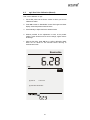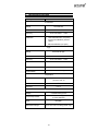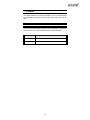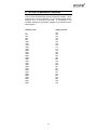
1
TABLE OF CONTENTS
1. INTRODUCTION
1
2. UNPACKING THE METER
2
3. GETTING STARTED
3.1.
Connectors
4. USING THE METER
4.1.
4.2.
4.3.
The Electrode
Display/ Keys
Screen Display
5. SETUP PROCEDURE CHECK
5.1.
Using Setup
5.1.1.
Setup Page 1: View last calibration factor
5.1.2.
Setup page 2: Select % Sat Mode
5.1.3.
Setup Page 3: Set the mg/L mode
5.1.4.
Setup Page 4: Set the Pressure
5.1.5.
Setup Page 5: Set the Salinity Value
5.1.6.
Setup Page 6: Select Number of User Cal Points for
% Sat calibration
5.1.7.
Setup Page 7: Enable/ Disable Auto Cal
5.1.8.
Setup Page 8: Select the Temperature Unit
5.1.9.
Setup Page 9: Enable/ Disable Stability Indicator
5.1.10. Setup Page 10: Clear the Calibrated Buffers
6. USER CALIBRATION
6.1.
6.2.
6.3.
6.4.
6.5.
6.6.
%Sat- One Point Calibration (Auto)
%Sat – Two Point Calibration (Auto)
%Sat- One Point Calibration (Manual)
mg/L- One Point Calibration (Auto)
mg/L One Point Calibration (Manual)
ATC Calibration
3
3
4
4
5
6
7
7
10
12
13
14
16
17
17
19
21
22
24
25
25
26
27
28
29
30
7. DO THEORY
31
8. METER SPECIFICATIONS
32
9. CLEANING
33
10. TROUBLESHOOTING
33
11. SETTING THE BAROMETRIC PRESSURE
34
12. WARRANTY
35
13. NOTICE OF COMPLIANCE
36
14. REPLACEMENT PARTS AND ACCESSORIES
37
1.
INTRODUCTION
Thank you for selecting a Fisher Scientific Accumet Dissolved
Oxygen bench-top meter. This instruction manual describes the
operation of the meter. The state-of-art meter that you have
purchased is easy to operate and will guide you through the various
functions by displaying easy to understand prompts.
This meter is designed to provide all the information necessary to
guide the user through the process of measuring DO with a series of
prompts on the screen.
The Accumet BASIC AB40 provides microprocessor precision in a
compact bench top design that’s easy to use. Five function keys
control all procedures, letting you:
•
Set the barometric pressure
•
Set the salinity value of the sample
•
Read DO in mg/L or % Saturation
It all adds up to rapid, completely automatic, intuitive operation.
)
You will find this symbol appearing in this manual; it indicates useful
tips that ease your meter operation.
1
2.
UNPACKING THE METER
The following is a listing of what you should have received with your
new Accumet AB40 Dissolved Oxygen meter:
Meter with kit includes:
•
•
•
•
•
meter
power supply
BOD probe
membrane kit
Instruction manual
Meter only includes:
•
•
•
meter
power supply
Instruction manual
If any of these items are missing, please contact the Fisher Lab
Equipment Group Electrochemistry Division by dialing 1888-3584706.
Accessories are available and can be ordered by calling Fisher
Scientific Customer Service at 1888-358-4706.
BOD probe: 13-620-SSP
Membrane kit: 13-637-DOM
2
3.
3.1.
GETTING STARTED
Connectors
1. Review the layout and arrangement of the rear connector panel.
2. Connect the power adapter’s output power jack to the meter’s
rear panel DC input power socket and plug in the adapter to a
power source.
3
4.
4.1.
USING THE METER
The Electrode
This meter comes equipped with a self-stirring BOD probe, model
5010, from YSI. Read the accompanying manual prior to installation
and operation. The 5010 probe need be plugged into the meter only,
as the meter supplies both its operation power and stirring power.
1. Prepare the electrode as described in its instruction manual.
2. Plug the electrode into the DO socket located at the rear panel of
the meter.
3. Place the probe into a BOD bottle filled with at least 1 inch of
water. Allow the probe to warm up for 30 minutes before
calibration or taking a measurement.
4
4.2.
Display/ Keys
Overview of the meter screen display and function key layout.
Press std key to initiate
standardization from measure
mode or press std key at the
Standardization mode to
confirm the standardization
and return to measurement
mode.
% Sat
Press
to adjust values/
selection.
Press setup key to access
setup for configuration of meter
settings.
Press enter key to confirm
selection or change being
made.
Press stdby key to start up or
put the meter in standby mode
Meter Display: AB 40
5
4.3.
Screen Display
Familiarize yourself with the layout of the digital screen display.
6
5.
5.1.
SETUP PROCEDURE CHECK
Using Setup
Setup allows you to set the operating parameters of the meter to
meet your requirements. There are two ways to access setup, and
the parameters that you can set will be different depending on how
you accessed setup. Determine which access route you need to
utilize from the chart below:
To set the following parameter
Access Setup from the following screen
View the last calibration factor
From the Measurement Mode Screen
Select the type of measurement
unit you wish to measure dissolved
oxygen in %Sat, mg/L and
associated units.
From the Measurement Mode Screen
Select the pressure value
From the Measurement Mode Screen
Select the salinity value
From the Measurement Mode Screen
Select the number of Calibration
Points (For %Sat mode only)
From the Measurement Mode Screen
Enable/ Disable Auto Calibration
From the Measurement Mode Screen
Select Temperature units
From the Measurement Mode Screen
Enable/ Disable Stability Indicator
From the Measurement Mode Screen
Clear Standardization
From the Measurement Mode Screen
7
The setup button is in essence a scroll key which allows you to
change several operating parameters. While in the setup mode you
may:
std
Press std to exit from setup to measure screen
without making change.
Press
setup
to set values within each setup option.
Press setup to scroll to the next parameter to view
or change.
enter
Press enter to accept the displayed parameter. The
meter will then return to the measurement mode.
stdby
Press stdby to return to the standby mode without
making a change. Pressing standby again will place
the meter in the Measure mode.
8
Setup Page 1: View last
calibrated Calibration
Factor
STD Solution
Setup Page 6 & 7:
Select number of
calibration points for
%Sat calibration
- View the last calibration factor
and 0% offset value.
Note: You will be able to view both Cal
Factor and 0%Sat offset ONLY if you had
- Select 1 point or 2 point
calibration for %Saturation.
Setup Page 2: Select %
Sat mode
Setup Page 8 & 9:
Select Auto Calibration
- Select to measure DO in %Sat.
- Set Auto calibration or
Manual calibration for %Sat
and mg/L.
Setup Page 3: Set mg/L
mode
Setup Page 10 & 11:
Select Temperature Unit
% Sat
% Sat
- Select to measure DO in mg/L.
select
- Select unit of measure for
Temperature either in °C or °F.
°C
mg/L
Setup Page 4: Set the
Pressure (450 mmHg825 mmHg)
mmHg
STABLE
Setup Page 12:
Enable Stability Indicator
-Set the stability indicator to be
displayed on the screen. Select
On.
- Adjust and select Pressure
value.
Setup Page 5: Set the
Salinity (0.0 - 45.0 ppt)
STABLE
- Adjust and Select salinity
value.
Setup Page 13:
Disable Stability
Indicator
-Set the stability indicator to be
NOT displayed on the screen.
Select OFF.
Salinity
mg/L
% Sat
clear
BUFFER
Overview of Setup Menus in AB 40
9
Setup Page 14: Clear
Standardization
- Select to clear standardization.
5.1.1.
Setup Page 1: View last calibration factor
This setup menu allows you to view the last calibration factor in % Sat
after standardization is successfully done.
To view last calibration factor
1.
Access the View Last calibration factor setup page by pressing
setup while in measurement mode to view the last calibration
factor.
press setup to select options
press enter to accept
10
2.
If the unit has not been standardized, a series of dashes will
appear on the display rather than a number.
3. Press enter to return to measurement mode
OR
4. Press setup to go to the next setup option without making any
changes.
)
If you access this setup page from %Sat mode and if you have
calibrated one point (100% Sat) then you can view the last calibration
factor. Should you have calibrated 2 points (100%Sat and 0%Sat),
you will be able to view both the last calibration factor and 0% offset.
If you access the setup page from mg/L mode, and if you have
calibrated mg/L, you will be able to view the last calibrated value in
mg/L.
11
5.1.2.
Setup page 2: Select % Sat Mode
The setup option allows you to measure DO in % Sat.
To select % sat Mode
1. Access the Select % Sat Mode setup page by pressing the setup
key while in measurement mode till page displays as figure
shown below.
2. Press enter to accept the option of measurement in % Sat Mode
and return to measurement mode
OR
3. Press setup again to go to the next setup page without making
any changes.
% Sat
12
5.1.3.
Setup Page 3: Set the mg/L mode
The setup option allows you to measure DO in mg/L.
To select mg/L mode
1. Access the Select mg/L setup page by pressing the setup key
while in measurement mode till the page displays as figure shown
below.
2. Press enter to accept the option of measurement in mg/L Mode
and return to measurement mode
OR
3. Press setup to go to next setup page without making any
changes.
mg/L
13
5.1.4.
Setup Page 4: Set the Pressure
The setup option allows you to set the atmospheric pressure (mmHg)
value. You are able to set the pressure value in the range of
(450mmHg to 825 mmHg).
To set Pressure
1. Access the Set the Pressure (mmHg) setup page by pressing the
setup key while in measurement mode till the page displays as
figure shown below.
2. Press enter to accept the current pressure value and return to
measurement mode
OR
3. Press
to adjust and set the value.
mmHg
press
to set value
press setup to select options
press enter to accept
14
4. Press enter key to confirm selection and return to measurement
mode.
OR
5. Press setup to go to next setup page without making any
changes.
)
You can escape setup mode at any time by pressing std.
Pressing enter will always return the display to measurement
mode after accepting the setup option.
15
5.1.5.
Setup Page 5: Set the Salinity Value
The setup option allows you to set the Salinity (as ppt) value. You are
able to set the salinity value in the range of 0.0- 45.0 ppt.
To set Salinity
1. Access the Set the salinity (ppt) setup page by pressing the
setup while in measurement mode key till the page displays as
shown below.
2. Press enter to accept the current salinity value and return to
measurement mode.
OR
3. Press
to adjust and set the value.
4. Press enter key to confirm selection and return to measurement
mode.
5. Press setup to go to next setup page without making any
changes.
Salinity
press
to set value
press setup to select options
press enter to accept
16
5.1.6.
Setup Page 6: Select Number of User Cal Points for
% Sat calibration
This setup option allows you to select the number of user calibration
points for % Sat calibration to be either 1 or 2.
To Select Number of User Cal Points
1. Access the Select Number of User Cal Points setup page by
pressing the setup key while in measurement mode till the page
displays as shown in the following page.
2. Press enter to accept the current User Cal Point (1) and return to
measurement mode.
OR
Press setup to go to next setup page which is User Cal Point (2)
setup page.
3. Press enter to accept selection and return to measurement
mode.
OR
Press setup again to go to next setup option without making any
changes.
17
% Sat
press setup to select options
press enter to accept
18
5.1.7.
Setup Page 7: Enable/ Disable Auto Cal
This setup option allows you to enable the auto calibration for % Sat
and mg/L modes.
To Enable/ Disable Auto Cal
1. Access the Auto Cal setup page by pressing the setup key while
in measurement mode till the page displays as shown in the
following page.
2. Press enter to accept (YES) to enable auto calibration and return
to measurement screen
OR
Press setup to go to Disable Auto Cal Page (NO).
3. Press enter key to confirm selection
OR
Press setup again to go to next setup option without making any
changes.
19
press setup to select options
press enter to accept
20
5.1.8.
Setup Page 8: Select the Temperature Unit
This setup option allows you to select unit of measure for
Temperature either in °C or °F.
To Select Temperature Unit
1.
Access the Select Temperature Unit setup page by pressing the
setup key while in measurement mode till the page displays as
shown below. a
select
2.
Press enter to accept the °C temperature unit and return to the
Measure screen
OR
Press setup again to display the °F temperature unit setup page
as shown below.
select
3.
Press enter to accept the °F temperature unit and return to the
Measure screen
OR
4.
Press setup to go to next setup option without making any
changes.
21
5.1.9.
Setup Page 9: Enable/ Disable Stability Indicator
This setup option allows you to set the stability indicator to be
displayed on the screen whenever reading has stabilized, thus
minimizes guesswork.
To Set Stability Indicator
1. Access the Set Stability Indicator setup page by pressing the
setup key while in measurement mode till the page displays as
shown below.
2. Press enter to accept (ON) to enable stability indicator and return
to measurement screen
OR
Press setup to go to Disable Stability Indicator (OFF) setup page
as shown on the following page.
3. Press enter key to confirm selection and return to measurement
mode
OR
Press setup again to go to next setup option without making any
changes.
STABLE
press setup to select options
press enter to accept
22
STABLE
press setup to select options
press enter to accept
23
5.1.10.
Setup Page 10: Clear the Calibrated Buffers
This setup option allows you to clear the Calibrated Buffers.
To Clear the Calibrated Buffers
1. Access the Clear Calibrated Buffers setup page by pressing the
setup key till the page displays as shown below.
2. Press enter key to make selection and return to measurement
mode
OR
Press the setup key return to measurement mode without
making any changes.
mg/L
% Sat
clear
BUFFER
press setup to select options
press enter to accept
)
1. If you access this page from %Sat measurement mode, the
above action clears both %Sat and mg/L calibration.
2. If you access this setup page from mg/L measurement mode, the
above action only clears mg/L calibration.
24
6.
6.1.
USER CALIBRATION
%Sat- One Point Calibration (Auto)
User can do the 100%Sat calibration. The pressure that has been set
in the setup will be applied only during the calibration.
Accepted window for 100% Sat calibration is 30% - 200%Sat. (Any
value that falls within this range will be accepted as 100%Sat)
Press std to enter to ‘Standardize’ screen. Upper display shows the
present measured value, while lower display shows the pressure
compensated 100% sat.
Hold probe in air.
Wait for the upper display value is stabilized. Press std key to confirm
calibration. Meter blinks the calibration values for few seconds before
exiting to measurement mode.
Standa rdize
% Sat
press std to standardize
25
6.2.
%Sat – Two Point Calibration (Auto)
The 0.0%Sat calibration has to be done first if a 2-point %Sat
calibration is selected. The 0.0%Sat calibration point will be
considered as offset.
)
After successful 0%Sat calibration, meter will prompt for the 100%
Sat calibration. User must do the two points. Otherwise meter
displays an error message. Press enter if meter displays the error
message.
Accepted window for 0% Sat Calibration is below 5% Sat.
Accepted window for 100% Sat Calibration = 30% - 200%Sat
1. Press std to enter to ‘Standardize’ screen. Upper display shows
the present measured value, while lower display shows the
0.0%Sat.
2. Put the DO electrode into 0%Sat solution.
3. Wait for the upper display value to be stabilized. Press std key to
confirm calibration. Meter blinks the cal values for few seconds
and prompts for the 100%Sat calibration.
4. Upper display shows the present %Sat value and lower display
shows the pressure compensated 100%Sat value.
5. Hold the DO probe in air, for 100%Sat calibration.
6. After the upper display reading stabilized, press std to confirm
the reading. Meter blinks the calibrated value for few seconds
before it returns to measurement mode.
Sta nda rdize
Standa rdize
% Sat
% Sat
press std to standardize
press std to standardize
26
6.3.
%Sat- One Point Calibration (Manual)
User can calibrate to the known value. The accepted window is set to
70% of the default value. Lowest value that can be calibrated is 20.0
%Sat.
1. Press std to enter to ‘Standardize’ screen. Both Upper and lower
display shows the present measured value.
2. Put the electrode into the solution to which you want to calibrate.
Wait for the upper display value to be stabilized. Use
key to
adjust the lower display to the known cal value.
3. Press std to confirm the reading. Meter blinks the cal values for
few seconds before returning to measurement mode.
Standa rdize
% Sat
STABLE
press
to set value
press std to standardize
27
6.4.
mg/L- One Point Calibration (Auto)
User can do calibration in mg/L.
1. Hold the DO probe in air; wait for the upper display reading to
stabilize.
2. Press std to enter to ‘Standardize’ screen. Upper display shows
the present measured value while lower display shows theoretical
value. [Based on pressure and salinity setting]
3. User can just confirm the theoretical reading.
4. Acceptance window is ±70% of the present measured value.
5. Press std key to confirm calibration. Meter blinks the cal values
for few seconds before returning to measurement mode.
Standa rdize
mg/L
STABLE
press std to standardize
28
6.5.
mg/L One Point Calibration (Manual)
User can do calibration in mg/L.
1. Put the DO probe into the known solution to which you want to
calibrate the meter.
2. Press std to enter to ‘Standardize’ screen. Both upper and lower
display shows the present measured value.
3. Use the
key to adjust the known standard value.
4. Window provided for the adjustment is ±70% of the present
reading. Lower value that can be set is 2.00mg/L; higher value is
60.00 mg/L.
5.
After set the value, press std key to confirm calibration. Meter
blinks the cal values for few seconds before returning to
measurement mode.
Standa rdize
mg/L
STABLE
press
to set value
press std to standardize
29
6.6.
ATC Calibration
User can adjust the ATC temperature offset.
)
DO/BOD probe must be connected to be able to access the ATC
calibration setup page.
To access the temperature calibration mode:
1. Connect DO/BOD probe to back panel of the meter.
2. From the stdby mode, PRESS AND HOLD setup key followed
by the stdby key.
3. Release the stdby key while holding on to the setup key.
4. Release the setup key after seeing the following screen.
5. Put the probe into the known temperature bath. Wait for reading
to stabilize.
6. Use the
key to adjust the offset.
7. After set the value, press std to confirm calibration.
Standa rdize
press
to set value
press std to standardize
ATC
30
7.
DO THEORY
The polarographic type Oxygen probe used with the Accumet AB40
meter responds to the partial pressure exerted by oxygen in a given
sample. As Oxygen reaches the probe's cathode, it is reduced
according to the following equation:
O2 + 2 H2O + 4e- = 4 OHWhen oxygen is reduced at the cathode (along with concurrent
oxidation of silver at the anode) current flows through the cell. The
more oxygen that is reduced, the more current is generated. The
relationship is linear, and by measuring the current generated in a
sample, and comparing it to that of a standard, one can compute the
amount of oxygen in the sample.
The primary influence on how much oxygen reaches the anode is the
partial pressure exerted by oxygen on the probes’ membrane. More
partial pressure brings more oxygen, and therefore more current. The
partial pressure that oxygen exerts is fixed for a given temperature
and atmospheric pressure. This fixed level corresponds to the
saturation level for a given temperature and pressure. The AB40
meter uses the known relationship between these parameters to
permit simple, automatic standardization.
In sample measurements, however, another factor influences the
relationship among partial pressure, temperature, and dissolved
oxygen. This is the factor of how much salt is contained or dissolved
in the sample. The presence of dissolved salt lowers the sample’s
ability to dissolve oxygen. Therefore a sample with a high level of
dissolved salt will contain less oxygen than a sample with less or no
salt at the same temperature and pressure. Fortunately, the
relationship between dissolved salt or salinity and dissolved oxygen is
well defined. The Accumet AB40 uses this fact to provide accurate
dissolved oxygen measurements in samples whose salinity range
from 0 to 40 ppt.
31
8.
METER SPECIFICATIONS
Description
Accumet AB 40
% Saturation
Range
0.0 to 600.0%
Resolution
0.1
Accuracy
Calibration
±0.5% Full Scale + 1 LSD
•
User selectable Auto one (100%)
or two point calibration (0% and
100%).
•
Manual calibration (one point)
mg/L
Range
0.00 to 60.00 mg/L
Resolution
0.01
Accuracy
±0.5% Full Scale + 1 LSD
Calibration
Manual and Auto.
Salinity Correction
0.0 to 45.0 ppt
Barometric pressure
compensation
450 to 825 mmHg
Temperature
Range
-5.0 to 46.0 °C
( 23.0 to 114.8 °F)
Calibration
YES
Accuracy
Display
Power Requirement
0.3 °C
3” (W) X 4¼”(H) Custom LCD with
contrasted background
12VDC, centre negative
(11VAC/ 220VAC)
Input
Dimension/ Weight
DIN (DO)
140 X 191 X 83 cm; 800 g (meter only)
32
9. CLEANING
This meter requires no regular maintenance, but it is recommended
to occasionally wipe down the front with a damp cloth from time to
time.
10. TROUBLESHOOTING
The Accumet AB40 displays pertinent error messages to guide you
should an error occur with a measurement or meter operation.
Message
Description
Error Icon
Error message for %Sat Cal error.
“---“
DO reading is out of range
33
11. SETTING THE BAROMETRIC PRESSURE
Use the actual local barometric pressure whenever possible. This is
obtained from a mercury barometer. Do not use the weather bureau
pressure, as it is corrected to sea level. If a barometer is not
available, estimate the atmospheric pressure at your altitude from the
following table:
Altitude in feet
mmHg pressure
0
200
400
600
800
1000
1200
1400
1600
1800
2000
2200
2400
2600
2800
3000
3200
3400
3600
3800
4000
4200
4400
4600
4800
5000
5200
5400
5600
760
754
749
744
738
733
728
722
717
712
707
702
696
692
686
681
676
672
666
661
657
652
647
642
637
632
628
623
618
34
12. WARRANTY
The Fisher Scientific Company (“Fisher”) warrants to the direct
purchaser that the accumet AB40 meter and DO probe will be free
from defects in material or workmanship for a specified warranty
period. During that period, Fisher will repair or replace the product or
provide credit, at its sole option, upon prompt notification and
compliance with its instructions. For accumet meters, that specified
period is 24 months from delivery date. For the electrode, that
specified period is 12 months.
Unless otherwise agreed, the warranty is limited to the country in
which the product is sold.
No Fisher employee, agent or representative has the authority to bind
Fisher to any oral representation or warranty concerning any product
sold. Any oral representation or warranty made prior to purchase of
any product and not set forth in writing and signed by a duly
authorized officer of Fisher shall no be enforceable by the purchaser.
FISHER EXPRESSLY DISCLAIMS ALL OTHER WARRANTIES,
EXPRESS OR IMPLIED, INCLUDING THE IMPLIED WARRANTY
OF MERCHANTABILITY AND FITNESS FOR A PARTICULAR
PURPOSE.
Fisher’s sole responsibility and the purchaser’s exclusive remedy for
any claim arising out of the purchase of any product listed above is
repair, replacement or credit as described above, where applicable.
In no event: 1) shall the cost of the exclusive remedy exceed the
purchase price: 2) shall Fisher be liable for any special, indirect,
incidental, consequential, or exemplary damages, howsoever arising,
even if Fisher has been advised of the possibility of such damages.
Each article that Fisher furnishes will conform to the written
specifications given in this manual, or those of a further improved
model. Changes are made often to the information in the manual and
will be incorporated into future editions.
35
13. NOTICE OF COMPLIANCE
Warning
This meter generates, uses, and can radiate radio frequency energy.
If not installed and used properly, that is in strict accordance with the
manufacturer’s instructions, it may cause interference to radio
communications. It has been tested and found to comply with the
limits for a Class A computing device pursuant to Subpart J of Part 15
of FCC Rules, which are designed to provide reasonable protection
against such interference when operated in a commercial
environment. Operation of this equipment in a residential area may
cause interference, in which case the user, at his own expense, will
be required to take whenever measures may be required to correct
the interference.
This product is to be used only as described in the manual. This
product is for indoor use only, and must be used in a well ventilated
area.
Warning!
To meet or exceed FCC regulations and comply with CE
requirements, the Fisher Scientific supplied power supply must
be used. Use of a power supply that is not approved by Fisher
Scientific may cause safety hazards and/or cause unit to exceed
EMC limits and/or damage unit. When using his meter with a
computer or printer, a shielded RS232 cable must be used to
meet or exceed FCC regulations, and comply with CE Mark
requirements.
36
14. REPLACEMENT PARTS AND ACCESSORIES
Description
Fisher Catalog Number
AB40 meter kit includes meter, selfstirring BOD probe (13-620-SSP),
membrane kit (13-620-DOM), user
manual and power supply.
13-636-AB40
Accumet self-stirring BOD probe
13-620-SSP
Adapter allows use of YSITM DO
probes with Accumet meter
13-637-DOADPT
Dissolved oxygen membrane kit.
Includes
6
membrane
caps,
polishing disk and electrolyte filling
solution.
13-637-DOM
To place an order, please call 1-888-358-4706.
37
68X296001 Rev. 1D
01/04