1
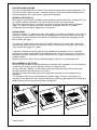
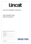
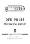
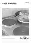
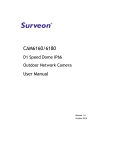
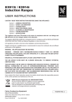
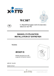
User and Installation Instructions
Twin Zone Induction Hob
IH21
IS429:ECN3369
IMPORTANT
PLEASE READ THESE INSTRUCTIONS CAREFULLY BEFORE USING THE EQUIPMENT. KEEP
THEM IN A SAFE PLACE FOR FUTURE REFERENCE.
All Lincat electrical appliances must be installed, operated and serviced by a competent person. Users
should take care to adopt safe working practices when operating or cleaning appliances. Please contact
your local distributor for further advice.
WARNING
APPLIANCES MUST BE EARTHED.
ISOLATE THE POWER SUPPLY BEFORE CARRYING OUT ANY INSTALLATION OR
MAINTENANCE WORK.
PARTS OF APPLIANCES BECOME HOT DURING NORMAL USE, TAKE CARE TO AVOID
ACCIDENTAL BURNS.
IF THE CERAMIC GLASS SURFACE IS CRACKED, IMMEDIATELY DISCONNECT THE APPLIANCE
FROM THE SUPPLY.
CAUTION SYMBOL: Non-ionising electromagnetic radiation (magnetic field).
WARNING SYMBOL: Dangerous voltage (live parts at a working voltage exceeding 250v).
INSTALLATION
1.
Ensure that the electricity supply is adequate for the equipment being installed.
2.
Partitions, walls, kitchen furniture and other materials less than 100mm from the appliance
should be made from non-combustible material.
3.
Remove all protective plastic coating from the unit.
4.
When siting the equipment, make sure that it is level and that there is a free flow of cool air
around the unit and that vents are not blocked.
5.
All appliances with an electric load of 3kW and below are fitted with a BS1363 fused plug and
should be connected to an earthed socket.
6.
Appliances must be installed in accordance with: Health & Safety at Work Act, IEE Wiring
Regulations, BS Codes of Practice, Local and National Building Regulations and Fire
Precautions Act 1971.
7.
If the supply cord is damaged, it must be replaced by the manufacturer, its service agent or
similarly qualified persons in order to avoid a hazard.
GENERAL USE
1.
The following convention applies where indicator lights are fitted to appliances:Green on - power to the unit.
2.
When the IH21 Induction hob is plugged into the 13amp mains supply and switched on, the
green neon light will illuminate and the cooling fan will be heard running.
3.
After use, switch the hob zone off by means of its control. Do not rely on the pan detector.
4.
Aluminium foil and plastic vessels are not to be placed on hot glass ceramic surfaces. Do not
use these surfaces for storage.
5.
Metallic objects should not be placed on the hob surface within the cooking zones since they
could get hot. Take care when operating the appliance as rings, watches and similar objects
could get hot when in close proximity to the hob surface.
6.
Only use pans of the type and size recommended, refer to ‘pan selection’ notes.
7.
Users with heart pacemakers should consult with the manufacturer of the pacemaker or their
doctor.
IS429:ECN3369
USER MAINTENANCE
1.
Before working on or cleaning the equipment, isolate it from the power supply and allow it to
cool to a safe working temperature.
2.
Clean units regularly with hot water and detergent, do not use abrasive or chlorine based
cleaners on stainless steel. Take care to avoid wetting electrical components.
Do not use a water jet.
3.
Clean the ceramic glass regularly. Avoid abrasive sponges or scouring agents and harsh
chemical cleaners like oven sprays. Remove dirt and food with a scraper or Vileda CERAN
cleaning sponge.
Once the ceramic glass has cooled, use a few drops of suitable cleaner on a paper towel or the
rough side of the sponge. Wipe the ceramic glass with a damp cloth and dry it with a clean cloth
or the smooth side of the sponge
If plastic, aluminium foil, sugar or sugary food has dropped onto hot ceramic glass,
scrape it off immediately. If these substances melt they can damage the surface.
4.
Check the air filter regularly and replace if it is contaminated.
INDUCTION COOKING AND PAN SELECTION
With induction cooking, heat is produced directly in the base of the pan. The system comprises a
ceramic glass hob surface with an induction coil beneath it. The coil generates an alternating magnetic
field. When a pan with a magnetic base is placed on the cooking zone, eddy currents are created in the
base of the pan leading to the production of heat. The pan heats very quickly.
The quality of the cookware is important to the efficiency of induction cooking. The base of the pan
needs to be flat and with good heat distribution.
Generally;
Suitable pans are made from cast iron, enamelled steel and stainless steel with a magnetic base.
Unsuitable pans are glass, earthenware, aluminium, copper and non-magnetic stainless steel.
Operation of the pan detection system is dependent on the size of the pan and its material.
Power available from the induction coil to the pan will vary and is dependent on size and pan material.
Induction generators make buzzing, whistling and clicking noises especially on lower power settings.
This is normal for this type of equipment.
The pan should be located concentrically over the ceramic glass target ring. If the inner ring of the
ceramic glass is visible around the pan, then the pan is too small.
RECOMMENDED PAN BASE DIAMETER
Recommended minimum pan
Limit of pan detection
Nominal coil diameter
IS429:ECN3369
Rear Zone
Ø180mm
Ø135mm
Ø210mm
Front Zone
Ø120mm
Ø90mm
Ø145mm
CONTROL KNOB FUNCTION AND HOB DISPLAY SYMBOLS
OFF
LOW TEMP HOLD
AUTOMATIC HEAT-UP
& CONTROL LOCK
LEVEL 1
POWER BOOST
LEVEL 2
LEVEL 9
HOB INDICATOR
LEVEL 8
LEVEL 3
LEVEL 7
LEVEL 6
LEVEL 4
LEVEL 5
Warning: Do not move the control knob directly between Power boost and Automatic heat-up.
All symbols are observed through the ceramic glass.
Low temperature hold
Power level setting 1 - 9
Power boost function
Automatic heat-up control
Control lock function
Pan detection (no pan present)
Residual heat display
Error codes – generator
Error – rotary control (lightning symbol)
IS429:ECN3369
LOW TEMPERATURE HOLD
The pan base temperature is monitored through the ceramic glass hobtop, allowing dishes to be kept
warm. The “u” symbol is displayed.
The food type, pan construction material and flatness of the pan base will have a significant effect on
the temperature of the pan contents. To comply with food minimum safe holding temperatures, pan lids
should be fitted and a temperature probe used frequently.
POWER LEVEL SETTING 1 – 9:
There are 9 power level settings available via the rotary control knob
The table below gives the percentage of maximum power for each level setting, also the time limit (in
minutes) for operation at that power.
Power level
% of Power
Time limit (mins)
Low temp hold
--120
1
3%
520
2
5%
402
3
8%
318
4
12%
260
5
18%
212
6
28%
170
7
42%
139
8
64%
113
9
100%
90
POWER BOOST FUNCTION
The IH21 is rated at 3kW total power input.
Normal operation; the large rear coil is rated at 2kw, the small front coil is rated at 1kw (total 3 kW).
If the large rear coil is power boosted, its power increases to 3kW, the front coil will be shut down.
If the small front coil is power boosted, its power increases to 1.8kW, the rear coil is limited to 1.2kW.
Power boost is activated by turning the control clockwise from the level 9 position.
Note: Only one coil can be boosted at a time.
The power boost will run for a maximum of 10 minutes, after that time the zone reverts to level 9. It may
be boosted again providing the system internal temperatures are satisfactory.
AUTOMATIC HEAT-UP CONTROL (AHC):
This is an advanced function.
When activated, the AHC will give maximum power (level 9) to a coil for a preset time before reducing
to a lower power level set by the control.
The table below gives the preset time for each level setting (in seconds) according to the power level.
Power level setting
Preset time (secs)
1
40
2
72
3
120
4
176
5
256
6
432
7
120
8
192
To activate; the control is turned anticlockwise from the ‘off’ position briefly whilst the “A” symbol
illuminates; the control is then turned clockwise to set the ‘final’ required power (1-8). The display will
revert to the “A” symbol and the induction hob will run at maximum power for the time shown in the
table above, before reducing power to the ‘final’ setting.
CONTROL LOCK FUNCTION
This function prevents unwanted operation of the induction hob, when the control lock is active; the “L”
symbol is displayed.
It is activated and de-activated by turning either control knob anticlockwise to the control-lock position
and held for approximately 6 seconds.
IS429:ECN3369
PAN DETECTION FUNCTION
Each zone has pan detection; this prevents the coil from turning on without a pan being present. The
coil also turns off as soon as the pan is removed. If the pan is of the wrong material to operate with
induction equipment, the ‘no pan present’ symbol will be displayed.
RESIDUAL HEAT DISPLAY
When a pan is removed from the hobtop and the temperature of the ceramic glass exceeds 60°C, the
“H” symbol is displayed indicating a hot surface. Refer also to the error codes section.
Whilst the residual heat display is showing, leave the IH21 Induction hob connected to the power
supply. This allows the internal cooling fans to continue to operate. When the “H” symbol is
extinguished, the mains power supply may be switched off.
ERROR CODES
There are numerous “E” symbol error codes, these identify issues within the induction system and are
primarily of use when reporting a fault to the Service department at Lincat Ltd. Some errors can be
cleared by turning the control to the “off” position, or completely turning off and unplugging the IH21,
before switching on again.
The “lightning” symbol reports errors due to the control knob circuit. If a control knob is wound anticlockwise and held in the “control lock” position in excess of 30 seconds, the system may assume a
“stuck control” and display this symbol.
A reduction in performance during cooking may be attributed to a blocked air filter, or a confined
location with insufficient cooling airflow, or a failed cooling fan. These circumstances will cause the
generator to overheat. Eventually the control electronics will shut down the generator causing the “H”
symbol to display.
Replacing the air filter and ensuring an adequate supply of cool air will restore performance.
REPLACEMENT OF AIR FILTER
Disconnect from the power supply after allowing the Induction hob to cool down. Turn the hob onto its
side or back, taking care not to scratch the ceramic glass cooking surface.
Push the slide latch sideways, this will allow the filter cover to be lifted away from the base panel.
Remove the old filter and replace with a clean filter.
Shut the filter cover onto the base panel ensuring that the slide latch has fully engaged into the
receptacle.
Turn the hob the right way up and reconnect to the power supply. The hob is now ready to use.
Important: Do not operate the IH21 Induction hob without a filter being fitted otherwise dirt and grease
could be drawn into the electronics and impair safe operation.
IS429:ECN3369
IH21 Induction Hob Specifications
Model
External height (mm)
External width (mm)
External depth (mm)
Net weight
Hob
Hob surface
Electrical supply 1N~+E
Electrical connection
Total power rating
Heat input rear zone, normal (kW)
Heat input rear zone, boost* (kW)
Heat input front zone, normal (kW)
Heat input front zone, boost* (kW)
(*) Max total heat input cannot exceed 3kW
IH21
115
350
654
12kg
2 zones
6mm thick Schott Ceran® ceramic glass
230V/1ph/50Hz
Fitted 2.0m long lead with 13amp plug
13 A
2.0
3.0
1.0
1.8
115
284
480
350
IH21 Induction hob spares
Replacement air filter
Control knob
Cooling fan
Vileda CERAN sponge
IS429:ECN3369
654
Part No
FI33
KN251
S/R0181
SERVICE INFORMATION
Catering equipment should be routinely serviced to ensure a long and trouble free life. With this in mind
it is recommended that appliances are serviced every six months by a competent engineer.
For help regarding the installation, maintenance and use of your Lincat equipment, please call:-
LINCAT SERVICE HELP DESK
01522 875520
AUTHORISED SERVICE AGENTS
We recommend that all servicing, other than routine cleaning, is carried out by our authorised service
agents and will accept no responsibility for work carried out by other persons. Note that for safe and
efficient operation, appliances need regular servicing.
Please quote both the model and serial numbers from the data plate attached to the unit. Give brief
details of the service requirement.
Lincat reserve the right to carry out any work under warranty during normal working hours, i.e. Monday
to Friday, 8.30 a.m. - 5.00 p.m.
CONDITIONS OF GUARANTEE
The guarantee does not cover: 1.
Accidental breakage or damage
2.
Operational misuse, wear and tear from normal usage, incorrect adjustment and neglect.
3.
Incorrect installation, maintenance, modification or unauthorised service work.
IS429:ECN3369