1
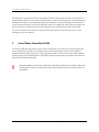
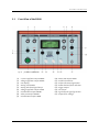
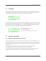
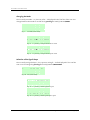
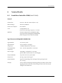
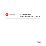
Training Aid
SOUND WAVE
CONTROLLER SC600
Ultrasound Generator with Accessories
for the Debye-Sears Test and
Projection of Standing Ultrasonic Waves
User Manual
www.gampt.de
Revision:
Version 1.01 EN, Dezember 10, 2015
Gesellschaft für Angewandte Medizinische Physik und Technik mbH
Hallesche Strasse 99F
06217 Merseburg
Tel.:
+49 3461/278691-0
Fax:
+49 3461/278691-101
Email:
[email protected]
Visit us on the internet: www.gampt.de
© 2015 GAMPT mbH
All rights are reserved for GAMPT mbH. No part of this manual may be reproduced or processed,
copied or distributed in any form without the prior approval of GAMPT mbH.
GAMPT mbH is not liable for damages occurring as a result of incorrect use, or for repairs and
alterations carried out by third parties not authorised by GAMPT mbH.
Subject to technical alterations. Errors excepted.
Printed: 12/10/2015
Version: 1.01 EN
Table of Contents
Table of Contents
1
Safety Instructions ........................................................................................................2
2
Introduction ................................................................................................................3
3
Sound Wave Controller SC600 .........................................................................................4
3.1
Front View of the SC600 ...........................................................................................5
3.2
Back of the SC600....................................................................................................6
3.3
LCD Display............................................................................................................7
3.4
Operation of the SC600 ............................................................................................7
4
3.4.1
Signal Generator (Frequency Generator)...............................................................7
3.4.2
Ultrasound Generator (ULTRASONIC UNIT).......................................................... 11
3.4.3
Voltage Supply for Laser Modules (LASER) ........................................................... 12
Accessories ................................................................................................................ 14
4.1
Ultrasonic Probe................................................................................................... 14
4.2
Laser Modules...................................................................................................... 14
4.3
Sample Reservoir and Probe Adjustment .................................................................. 15
4.4
Projection Lens .................................................................................................... 16
5
Practical Experiments .................................................................................................. 17
5.1
General Experiment Instructions ............................................................................. 17
5.2
Debye-Sears Effect ................................................................................................ 18
5.3
Projection of Standing Waves .................................................................................. 19
6
Technical Details ........................................................................................................ 21
6.1
Sound Wave Controller SC600 (GAMPT 20100) ............................................................ 21
6.2
Accessories .......................................................................................................... 22
7
!
Revisions of the user manual ........................................................................................ 24
Please read through the whole user manual before using the device and
accessories.
Sound Wave Controller SC600 · User Manual Version 1.01 EN
1
Safety Instructions
1
Safety Instructions
Please read through the following instructions thoroughly before commissioning the ultrasonic
generator and accessories for your own safety and the operational safety of the device.
The opening slits on the device are for ventilation and must be kept absolutely free in order to
prevent the device from overheating. It is recommended to use the folding feet on the device.
Make sure that the voltage values and fusing stated for the device are adhered to in the
electricity supply.
Never try to insert objects through the openings on the device, because this can lead to short
circuits or electric shocks.
Only connect the ultrasonic transducer supplied by the company GAMPT mbH to the output of
the ULTRASONIC unit marked PROBE. Be careful, there are voltages of up to 50 V and currents
of up to 1000 mA.
Do not operate the connected ultrasonic transducer without contact with a liquid, because it
can lead to overheating and thus to the destruction of the transducer.
Switch off the output PROBE of the SC600 if the ultrasonic probe is not connected or not
needed.
Because power ultrasound is produced with the device and the associated sonic transducer, the
sonic transducer must not be used on people or animals.
The laser modules currently supplied by us are equipped with laser diodes of the laser classes 2
and 3R (EN 60825-1) with a performance of ≤ 1 mW or ≤ 5 mW. Before using them, find out
about the necessary protective measures.
Do not switch on a laser module connected to the output LASER of the SC600 if there is a person
in the direction of the beam. Do not look into the laser beam and do not direct the laser at
other people or animals.
2
GAMPT mbH · Hallesche Straße 99F · D-06217 Merseburg · Tel. +49 3461/2786910 · www.gampt.de
Introduction
2
Introduction
In 1932 Debye and Sears showed for the first time that light undergoes diffraction when passing
through a liquid excited to high-frequency vibrations. Here, the density fluctuations caused by a
standing or travelling ultrasonic wave act like the grating elements of an optical diffraction grating.
The grating constant then corresponds to the wavelength of the ultrasound and is consequently
dependent on its frequency and its speed in the medium through which the waves are passing.
With the cw ultrasonic generator SC600 (4) from the company GAMPT mbH, the wide-band ultrasonic
probe (2), the sample reservoir (3) with adjuster and built-in laser support and a laser module (1),
there is a device set available with which this phenomenon can be demonstrated to trainees at
schools, colleges and universities in a simple and compact way (Fig. 1). With this, both the frequency
dependence can be demonstrated and the wavelength of the ultrasound in different liquids and thus
the material-specific sound velocity can be determined.
Fig. 1:
SC600 and Debye-Sears set
(1) laser module
(2) ultrasonic probe
(3) sample reservoir with probe adjustment and laser support
(4) Sound Wave Controller SC600
Sound Wave Controller SC600 · User Manual Version 1.01 EN
3
Sound Wave Controller SC600
Furthermore, it is possible to project a standing ultrasonic wave simply. For this, an optical lens is
placed between the laser source and ultrasonic wave, so that the standing wave is shone through by
divergent laser light. The periodically repeating fluctuations in density along the sonic beam axis
cause a varying refraction of the laser light. The result is an image with a distribution of bright and
dark areas, which is determined by the wavelength and thus the frequency of the ultrasound.
You can find further information on other possible applications and accessories in our current
catalogue and on our website.
3
Sound Wave Controller SC600
The device allows the generation of continuous sound waves (cw: continuous wave) at high power
over a wide frequency range up to 20 MHz and can also be operated in burst or pulse mode. In
addition to the ultrasonic generator, a signal generator and a control unit for laser diode modules
are also built-in. All adjustable device parameters and important output parameters are shown on
the centrally located LCD display.
!
4
Attention! SC600 and ultrasonic probes/laser modules are adapted to each other. Before you
use the probes of other manufacturers, please check whether the technical parameters are
compatible.
GAMPT mbH · Hallesche Straße 99F · D-06217 Merseburg · Tel. +49 3461/2786910 · www.gampt.de
Sound Wave Controller SC600
3.1
Front View of the SC600
Fig. 2:
(1)
(2)
(3)
(4)
(5)
(6)
(7)
(8)
(9)
front view of the SC600
current regulator output PROBE
voltage regulator output PROBE
LCD display
setting value/mode
setting selection/signal shape
voltage regulator output LASER
on/off button output PROBE
status LED output PROBE
on/off button output LASER
Sound Wave Controller SC600 · User Manual Version 1.01 EN
(10)
(11)
(12)
(13)
(14)
(15)
(16)
(17)
status LED output LASER
on/off switch device
output ultrasound generator
button decimal place selection
trigger output
TTL output
signal output signal generator
output laser voltage
5
Sound Wave Controller SC600
3.2
Back of the SC600
Fig. 4: view of the back of the SC600
On the back of the device there is a socket for the mains
connection. A fuse holder is built into the bottom part of the
socket. This holds the fuse for the device and a reserve fuse.
Changing the Fuse
To change the device fuse, the fuse holder must be pulled
out of the socket (Fig. 4).
Necessary fuse type:
!
!
6
T 1A (see section 6)
Fig. 3:
socket with partially pulled
out fuse holder
Caution! The device works with mains voltage. Touching voltage-carrying parts is dangerous
to life. Switch the device off and pull the mains cable out of the plug before you pull out the
fuse holder.
Attention! Only replace the fuse with the type stated in the manual. If the wrong type of fuse
is used, there is a risk of fire.
GAMPT mbH · Hallesche Straße 99F · D-06217 Merseburg · Tel. +49 3461/2786910 · www.gampt.de
Sound Wave Controller SC600
3.3
LCD Display
For the setting and presentation of the device parameters there is an LCD display with 4 lines, each
with 16 characters. About 2 seconds after the device is switched on, the welcome screen appears in
the LCD display, also stating the version number of the device software (Fig. 5).
G
S
V
M
A
o
e
a
M
f
r
e
Fig. 5:
P
t
s
r
T
mb H
S C 6 0 0
w a r e
i o n
2 . 1
z
2 0 1 3
welcome screen
After initialisation has finished, the start screen (Fig. 6) is displayed. Line 1 now contains information
on the operating mode and the signal shape. Line 2 is for displaying the setting values of the signal
generator. In lines 3 and 4, the voltage and current values on the PROBE output are shown on the
left, and on the right, the voltage value on the LASER output is displayed.
M
F
U
I
OD E :
CW
S
:
1 0 0 0 0 0 0
: 4 5 . 8 9 V
#
L A S
: 0 . 0 2 1 A
#
2 . 4
Fig. 6:
3.4
I
H
E
1
N
z
R
V
Line 1: signal mode and signal shape display
Line 2: setting value display
Line 3: ultrasonic voltage display
Line 4: ultrasonic current display and laser voltage display
start screen Version 2.1
Operation of the SC600
3.4.1 Signal Generator (Frequency Generator)
The built-in signal generator can generate signals with frequencies from 1 Hz to 20 MHz, which can
be digitally adjusted in steps of 1 Hz. As well as the cw mode (CW), the device can also be operated in
burst and pulse mode (BURST, PULSE). Sine, triangular and square wave signals (SIN, TRI, SQU) can
be generated.
The settings are made using two knobs with pressing function, (4) VALUE/MODE and (5)
SELECT/WAVEFORM, and the two buttons
(13) to select the decimal place.
The signal frequency can be tapped at the TTL output (15) as a square wave signal (0-5 V). At the
SIGNAL output (16), the generator signal is supplied according to the parameters set.
Sound Wave Controller SC600 · User Manual Version 1.01 EN
7
Sound Wave Controller SC600
Changing the Mode
The currently set mode – cw, burst or pulse – is displayed in the first line of the LCD. The
change between the modes is carried out by pressing the knob (4) VALUE/MODE.
M
F
U
I
OD E :
CW
S
:
1 0 0 0 0 0 0
: 4 5 . 8 9 V
#
L A S
: 0 . 0 2 1 A
#
2 . 4
Fig. 7:
I
H
E
1
N
z
R
V
cw mode (initial state)
M
F
U
I
OD E :
B
:
1
: 4 5 . 8 9
: 0 . 0 2 1
Fig. 8:
M
F
U
I
I
H
E
1
N
z
R
V
1 × pressing - change into the burst mode
OD E :
P
:
1
: 4 5 . 8 9
: 0 . 0 2 1
Fig. 9:
U R S T
S
0 0 0 0 0 0
V
#
L A S
A
#
2 . 4
U L S E
S
0 0 0 0 0 0
V
#
L A S
A
#
2 . 4
I
H
E
1
N
z
R
V
2 × pressing - change into the pulse mode
Selection of the Signal Shape
The currently set signal shape - sine, square or triangle – is also displayed in line 1 of the
LCD. It can be changed by pressing the knob (5) SELECT/WAVEFORM.
M
F
U
I
OD E :
CW
S
:
1 0 0 0 0 0 0
: 4 5 . 8 9 V
#
L A S
: 0 . 0 2 1 A
#
2 . 4
I
H
E
1
N
z
R
V
Fig. 10: sine (initial state)
M
F
U
I
OD E :
CW
S
:
1 0 0 0 0 0 0
: 4 5 . 8 9 V
#
L A S
: 0 . 0 2 1 A
#
2 . 4
Q
H
E
1
U
z
R
V
Fig. 11: 1 × pressing - selecting square signal
M
F
U
I
OD E :
CW
T
:
1 0 0 0 0 0 0
: 4 5 . 8 9 V
#
L A S
: 0 . 0 2 1 A
#
2 . 4
R
H
E
1
I
z
R
V
Fig. 12: 2 × pressing - selecting triangular signal
8
GAMPT mbH · Hallesche Straße 99F · D-06217 Merseburg · Tel. +49 3461/2786910 · www.gampt.de
Sound Wave Controller SC600
Selection and Display of the Signal Variables of the Generator Signal
The following signal variables, as shown in Table 1, can be displayed and changed at the
frequency and/or signal generator: signal frequency, signal amplitude, pulse repetition
frequency and burst length. The signal variable to be displayed and/or set is selected by
turning the knob (5) SELECT/WAVEFORM.
M
F
U
I
OD E :
CW
S
:
1 0 0 0 0 0 0
: 4 5 . 8 9 V
#
L A S
: 0 . 0 2 1 A
#
2 . 4
I
H
E
1
N
z
R
V
Fig. 13: frequency (initial state)
M
A
U
I
O
M
:
:
D
P
4
0
E :
CW
S
:
1 0 0 0
mV
5 . 8 9 V
#
L A S
. 0 2 1 A
#
2 . 4
I
s
E
1
N
s
R
V
Fig. 14: turn right – amplitude of the SIGNAL output
M
P
U
I
O
R
:
:
D
F
4
0
E :
:
5 . 8 9 V
. 0 2 1 A
CW
S
1 0 0 0
#
L A S
#
2 . 4
I
H
E
1
N
z
R
V
Fig. 15: turn right – pulse repetition frequency with burst and pulse
M
B
U
I
O
u
:
:
D
L
4
0
E :
:
5 . 8 9 V
. 0 2 1 A
CW
S
1 0
m
#
L A S
#
2 . 4
I
y
E
1
N
s
R
V
Fig. 16: turn right – burst length (is also equal to the double pulse
width in the pulse mode)
Sound Wave Controller SC600 · User Manual Version 1.01 EN
9
Sound Wave Controller SC600
Setting the Values of the Signal Variables
After the signal variable to be set has been selected (Fig. 13-16), the value of the signal
variable can be set using the knob (4) VALUE/MODE and the two buttons
(13). By turning
the knob (4) the value of the selected decimal place is changed. Turning to the left reduces
the value and turning to the right increases the value.
M
F
U
I
OD E :
CW
S
:
1 0 0 0 0 0 0
: 4 5 . 8 9 V
#
L A S
: 0 . 0 2 1 A
#
2 . 4
I
H
E
1
N
z
R
V
Fig. 17: initial state
M
F
U
I
OD E :
CW
S
:
1 1 0 0 0 0 0
: 4 5 . 8 9 V
#
L A S
: 0 . 0 2 1 A
#
2 . 4
I
H
E
1
N
z
R
V
Fig. 18: increase the value by turning right
M
F
U
I
OD E :
CW
S
:
9 0 0 0 0 0
: 4 5 . 8 9 V
#
L A S
: 0 . 0 2 1 A
#
2 . 4
I
H
E
1
N
z
R
V
Fig. 19: reduce the value by turning left
With the buttons
M
F
U
I
(13), the decimal place to be changed can be selected.
OD E :
CW
S
:
1 0 0 0 0 0 0
: 4 5 . 8 9 V
#
L A S
: 0 . 0 2 1 A
#
2 . 4
I
H
E
1
N
z
R
V
Fig. 20: initial state
M
F
U
I
OD E :
CW
S
:
1 0 0 0 0 0 0
: 4 5 . 8 9 V
#
L A S
: 0 . 0 2 1 A
#
2 . 4
Fig. 21: right button
M
F
U
I
10
N
z
R
V
– one place to the right
OD E :
CW
S
:
1 0 0 0 0 0 0
: 4 5 . 8 9 V
#
L A S
: 0 . 0 2 1 A
#
2 . 4
Fig. 22: left button
I
H
E
1
I
H
E
1
N
z
R
V
– one place to the left
GAMPT mbH · Hallesche Straße 99F · D-06217 Merseburg · Tel. +49 3461/2786910 · www.gampt.de
Sound Wave Controller SC600
Setting Values Signal Generator (Signal Variables)
The possible setting values of the signal variables are summarised in Table 1. The smallest
possible increment is given as the step size. The actual step size is dependent on the decimal
place that was selected beforehand in the setting.
Table 1: setting values for the signal variables of the signal generator.
Signal Variable
Unit
Minimum
Maximum
Step Size
Frequency
Hz
1
20 000 000
1
Amplitude
mVss
0
2 500
1
Pulse Repetition Frequency
Hz
1
20 000
1
Burst Length
µs
1
65 000
1
3.4.2 Ultrasound Generator (ULTRASONIC UNIT)
The connections and controls of the ultrasound generator are located on the left side of the device.
The multi-frequency probe from GAMPT is connected to the output marked PROBE (12). The sound
power is set via two knobs. With the left knob (1), the threshold value for the transmitting current
(CURRENT) is regulated. The transmitting voltage (VOLTAGE) is set with the right knob (2). The
possible setting values for current and voltage are summarised in Table 2. All other parameters such
as mode, signal frequency, pulse frequency, pulse repetition frequency or brush length are set using
the signal generator as described above (Section 3.3.1).
Table 2: setting values transmitting voltage und current limit on the ultrasound generator
Variable
Unit
Minimum
Maximum
Step Size
Voltage
V
2
50
Continuous
Current
mA
0
1 000
Continuous
The current values of transmitting voltage and current limit can be read in lines 3 and 4 of the LCD
display (3).
M
F
U
I
OD E :
CW
S
:
1 0 0 0 0 0 0
: 4 5 . 8 9 V
#
L A S
: 0 . 0 2 1 A
#
2 . 4
I
H
E
1
N
z
R
V
Fig. 23: voltage U and current I at the ultrasound generator
Sound Wave Controller SC600 · User Manual Version 1.01 EN
11
Sound Wave Controller SC600
The power supply of the ultrasonic probe can be switched on and off using the switch (7) (PROBE
ON/OFF). The status of the PROBE output (12) is displayed by the indicator LED (8) above the
connection. If the die LED lights up, the ultrasound generator output is switched on and the
ultrasonic probe is supplied with power.
!
!
Be careful! There can be voltages up to 50 V and currents up to 1000 mA at the PROBE output.
Switch off the PROBE output (indicator LED is off), if the ultrasonic probe is not connected or
not needed.
Attention! A high wattage is used in the ultrasonic probe, which leads to heating of the
probe. Do not operate the connected ultrasonic probe without contact to the test object
(liquid, sample reservoir etc.), because otherwise the probe will overheat and thus be
destroyed. Switch off the power supply of the probe via the switch (7), if the probe is not
required.
3.4.3 Voltage Supply for Laser Modules (LASER)
For the acousto-optical tests based upon the diffraction or refraction of light at an ultrasonic wave,
GAMPT supplies laser modules, the laser diodes of which continually emit monochromatic light in
the red, green or blue range of the visible spectrum.
You will find the connection and controls for the laser modules on the right side of the device front
under LASER. The laser module to be used is connected to the output marked LASER (17). The supply
voltage (Table 3) is set and regulated via the knob (6).
Table 3: setting values for supply voltage of laser
Variable
Unit
Minimum
Maximum
Step Size
Voltage
V
1.7
3.5
Continuous
The current voltage value at the LASER output (17) can be read in line 4 of the LCD display (3).
M
F
U
I
OD E :
CW
S
:
1 0 0 0 0 0 0
: 4 5 . 8 9 V
#
L A S
: 0 . 0 2 1 A
#
2 . 4
I
H
E
1
N
z
R
V
Fig. 24: display of the voltage at the LASER output
12
GAMPT mbH · Hallesche Straße 99F · D-06217 Merseburg · Tel. +49 3461/2786910 · www.gampt.de
Sound Wave Controller SC600
Below the knob (6) there is the on/off switch for the LASER output (17). The status of the output is
displayed via the indicator LED (10) below the on/off switch (9). If the LED lights up, the LASER
output is switched on and the connected laser module is supplied with power.
!
!
Attention! The laser modules supplied by GAMPT are equipped with laser diodes of the laser
classes 2 and 3R (EN 60825-1) with a wattage from ≤ 1 mW and/or ≤ 5 mW. Before using these
modules, please find out about the necessary protective measures.
Be careful! Do not switch on a connected laser module if there are people in the direction of
the beam. Do not look into the laser beam and do not direct the laser at other people or
animals. Switch the laser module off when you do not need it.
Sound Wave Controller SC600 · User Manual Version 1.01 EN
13
Accessories
4
Accessories
In the following, the accessories required for the Debye-Sears test and the projection of standing
ultrasonic waves are described. You can find information about other accessories in the GAMPT
Catalogue Education and on our website.
4.1
Ultrasonic Probe
Especially for use with the cw generators
SC500 and SC600, a multi-frequency probe
was developed by GAMPT that is
distinguished by very good sound-producing
characteristics in a frequency range from
1 MHz to over 10 MHz. It is equipped with a
robust metal housing and the sound
radiation surface is moulded to be
watertight. The probe can be directly
connected to the output PROBE of the
ultrasound generator of the SC600 via a
special LEMO plug.
!
4.2
(1)
(2)
(3)
(4)
multi-frequency probe
sound radiation surface, moulded
probe housing
connecting plug (LEMO)
connection cable
Be careful! Do not operate the
ultrasonic transducer without
contact with a liquid to avoid
overheating and thus the
destruction of the transducer (see
also chapter 3.4.2, page 11 ed seq).
Laser Modules
The laser modules of GAMPT are equipped
with red, green or blue laser diodes of the
laser classes 3R (green and red) and/or 2
(blue) for carrying out acousto-optical
experiments (Debye-Sears effect, projection
of standing ultrasonic waves etc.). For the
carrying out of experiments, the laser
14
Fig. 25:
Fig. 26:
(1)
(2)
(3)
(4)
laser module (red)
laser beam exit window
laser diode shell
coaxial power connector for connection to SC600
connection cable
GAMPT mbH · Hallesche Straße 99F · D-06217 Merseburg · Tel. +49 3461/2786910 · www.gampt.de
Accessories
modules are fastened in the laser support of the AOM sample reservoir (Fig. 27). Voltage is supplied
to the modules via the LASER unit of the SC600. For this, the laser module is connected via its coaxial
power connector (3) to the SC600.
4.3
Sample Reservoir and Probe Adjustment
The production of standing ultrasonic waves
takes place in a glass vessel open at the top (9).
Fig. 27:
(1)
(2)
(3)
(4)
(5)
(6)
(7)
(8)
(9)
cross-sectional diagram of sample
reservoir, cover with probe adjustment,
probe and laser support
adjustment screws for probe alignment
cover
probe support
ultrasonic probe
locking screw for laser module
holding well for projection lens
support for laser modules
locking screw for ultrasonic probe
glass vessel
Sound Wave Controller SC600 · User Manual Version 1.01 EN
The sample vessel is covered with a special
cover (2). The cover is equipped with a support
(3) for the ultrasonic probe (4). Cover and
probe support are connected to each other via
three tension springs and three adjustment
screws (1) so that the sound axis of the
ultrasonic probe being used can be aligned
exactly perpendicularly to the bottom of the
tank. Due to the possibility of three-point
adjustment, the incident sound wave and the
sound wave reflected at the vessel bottom can
be made to overlap precisely, thus producing a
standing ultrasonic wave.
A support (7) for a laser module is attached to
one wall of the sample vessel, so that the
sound wave can be shone through at a
perpendicular angle. The support is also
equipped with a holding well (6) for a
projection lens for the experiment of
projection a standing ultrasonic wave.
15
Accessories
4.4
Projection Lens
The projection lens consists of a rectangular glass substrate (2) with gripping surface (3) and the
actual optical lens (1). The lens is plano-convex and glued onto the glass substrate. For the
projection experiment the projection lens is pushed into the holding well of the laser support on the
sample vessel. The correct positioning of the projection lens is shown in Fig. 29.
Fig. 28:
(1)
(2)
(3)
top view of projection lens
plano-convex lens
glass substrate
gripping surface
Fig. 29: positioning of the projection lens
16
GAMPT mbH · Hallesche Straße 99F · D-06217 Merseburg · Tel. +49 3461/2786910 · www.gampt.de
Practical Experiments
5
Practical Experiments
The following list contains suggestions on practical experiments that can be carried out with the
SC600 and appropriate accessories. Brief descriptions of and information on the required equipment,
setting-up and performance can be found in our catalogue and on our website. The Debye-Sears
effect and the projection of standing waves are described in more detail in the sections 5.2 and 5.3.
PHY11
PHY12
PHY17
PHY19
PHY24
IND04
5.1
Debye-Sears Effect
Projection of Standing Waves
Acousto-Optical Modulation at Standing Waves
Phase and Group Velocity
Thermoacoustic Sensor
Concentration Measurement with Resonance Cell
General Experiment Instructions
The following instructions should be adhered to in order for the experiments to work:
•
•
•
•
•
•
•
If possible, degassed water is to be used because air bubbles interfere with the sound field as
well as the course of the laser light.
Air bubbles on the ultrasonic probe are to be removed.
The largest possible distances between the sample vessel and projection wall are to be used,
in order to enlarge the spacings between the diffraction orders and to minimise
measurement mistakes.
If no measurement is being carried out, the ultrasound should be switched off in order to
prevent the sample liquid from heating up.
For exact measurements, the temperature should be determined and compared.
For all frequencies up to 9 MHz, with higher voltages and a good orientation of the
transducer, at least two to three diffraction maxima should be visible.
The projection test is substantially more sensitive to tilting of the transducer than to light
diffraction. In the case of projection, the requirements for producing a standing wave must
be more closely adhered to.
Sound Wave Controller SC600 · User Manual Version 1.01 EN
17
Practical Experiments
5.2
Debye-Sears Effect
In 1932 Debye and Sears showed that light
undergoes diffraction when passing through
a liquid being excited into high-frequency
vibrations. By means of this effect,
ultrasound can be made more or less
"visible". When this effect is used, the
density maxima and minima produced in
Fig. 30: diffraction patterns for red laser light at sound
the liquid by a standing or travelling
frequencies of 3-10 MHz in steps of 1 MHz.
ultrasonic wave act like an optical
diffraction grating. The grating constant of
such a grating produced by an ultrasonic
wave corresponds to the wavelength of this
ultrasonic wave (Fig. 31). It can be
determined by means of the diffraction
patterns of the light of a laser beam of
known wavelength (Fig. 30). Because the
wavelength is defined by frequency and
sound velocity, the Debye-Sears effect can
be used in this experiment set-up to
determine - with a high degree of precision Fig. 31: diagram of the geometric conditions for the
the sound velocity in the liquid thorough
Debye-Sears test.
which the sound is passing. If the distance s
between ultrasonic wave and diffraction
pattern, the number N of diffraction maxima, the distance x between the –Nth and +Nth diffraction
order, the sound frequency ν and the wavelength λL of the laser light are known, the wavelength of
the sound λs and the sound velocity c in the liquid can be calculated according to the following
formulae:
λ S = 2N ⋅ λL
s
x
(1)
(2)
c = λS ⋅ ν
Example Measurements:
Table 4:
summary of given, measured and calculated values
Liquid
Given Values
Measured Values
Calculated Values
Literature
Values
ν in MHz
λL in nm
N
s in m
x in cm
λS in µm
c in m/s
c in m/s
Water
4
650 (rot)
4
2.9
4.1
367.8
1,471
1,480 at 20 °C
Glycerine
4
650 (rot)
2
2.9
1.6
471.2
1,885
1,900 at 25 °C
18
GAMPT mbH · Hallesche Straße 99F · D-06217 Merseburg · Tel. +49 3461/2786910 · www.gampt.de
Practical Experiments
5.3
Projection of Standing Waves
A standing ultrasonic wave in a liquid can
be directly imaged by means of divergent
monochromatic light. Due to the standing
wave, sound pressure differences are
produced in the liquid which repeat
periodically along the sound beam axis. The
localised density differences caused by this
result in spatially differing and periodically
repeating refraction indices along the
sound beam axis. When monochromatic
light is used, the projection of the standing
wave therefore shows a light-dark
modulation with periodically repeating
brightness maxima which correspond to the
density differences (Fig. 32).
To determine the wavelength from the
distribution pattern and the geometry,
refraction corrections due to the glass walls
and the measuring liquid must still be
taken into account (Fig. 33) as well as the
focal distance f of the lens in air. To
determine the wavelength exactly, it is
therefore recommended that the method of
light refraction be used, as described in
Section 5.2.
Fig. 32:
projection patterns of standing ultrasonic
waves in water at sound frequencies of
2.8 MHz, 3.5 MHz and 4.5 MHz, obtained with
red laser light.
Fig. 33:
diagram of the geometric conditions during the
projection of a standing ultrasonic wave.
The formula (3) states the exact calculation
2x
λS = ⋅
N
f−
g 1 a1
−
nG nL
⎛ g +g a +a ⎞
s − ⎜⎜ f − 1 2 − 1 2 ⎟⎟
nG
nL ⎠
⎝
(3)
rule for the sound wavelength λS from the
projection image. The spacing a1 between
sound field and glass wall on the lens side
and the distance a2 can be assumed, as an
approximation, to be half of the respective inside dimension. The thickness of the glass g1
corresponds to the sum of the wall thickness of the glass vessel and the thickness of the glass
substrate of the projection lens. The refraction indices nL of the measurement liquid and nG of the
glass must be determined or taken from the literature. N is the number of the brightness maxima
and x the respective distance. The sound velocity in the liquid is again calculated according to the
equation (2).
Sound Wave Controller SC600 · User Manual Version 1.01 EN
19
Practical Experiments
Comment: A good projection of the standing ultrasonic wave can usually only be achieved
for 4 MHz with the glass sample vessel that is supplied. Particularly for 1 MHz there can be
destructive overlapping of the incoming ultrasonic waves with the ultrasonic waves reflected
at the underside of the vessel bottom. For 8 MHz, the amplitude of the radiated ultrasonic
wave is too low and in addition the absorption is considerably higher (the absorption
coefficient is proportional to the frequency squared), so that no distinctly formed wave is
produced.
Example Measurement for Water:
Given values:
Table 5:
focal distance of the lens in air:
refraction index of glass:
refraction index of water:
sound frequency:
f
nG
nL
ν
= 10 cm
= 1.45
= 1.33
= 4 MHz
summary of the measurement values and results
Measured Values
Calculated Values
Literature
a1, 2 in cm
g1 in cm
g2 in cm
s in m
x in cm
N
λS in µm
c in m/s
c in m/s
4.8
0.5
0.4
3.03
8.9
9
397
1590
1,480 at 20 °C
20
GAMPT mbH · Hallesche Straße 99F · D-06217 Merseburg · Tel. +49 3461/2786910 · www.gampt.de
Technical Details
6
Technical Details
6.1
Sound Wave Controller SC600 (GAMPT 20100)
General
Dimensions:
255 mm × 170 mm × 265 mm (W × H × D)
Mains Voltage:
100-240 V, 50/60 Hz
Power Consumption:
max. 100 VA
Fuse:
T 1A (EN 60127-2-3)
G fuse link, time-lag, 1 ampere, 5 × 20 mm
Modules:
ultrasound generator (ULTRASONIC UNIT)
signal generator (FREQUENCY GENERATOR)
power supply for laser modules (LASER)
Signal Generator (FREQUENCY GENERATOR)
Signal Modes:
cw, burst or pulse
Signal Shapes:
sine, triangle or rectangle
Frequency:
≤ 20 MHz, adjustable in 1Hz steps
Pulse Repetition
Frequency:
1 Hz – 20 kHz, adjustable in 1 Hz steps
Burst Length:
1-65,000 µs, adjustable in 1 µs steps,
(pulse width in pulse mode = ½ burst length)
Output TRIGGER:
TTL pulse in burst or pulse mode
Output TTL:
0-5 Vpp, square wave signal
Output SIGNAL:
signal corresponding to the settings of the signal generator
at ≤ 2.5 Vpp
Display:
4-line LCD for the display and setting of the parameter values of the
signal generator and of the ultrasound generator and of the output
voltage of the LASER unit.
Sound Wave Controller SC600 · User Manual Version 1.01 EN
21
Technical Details
Ultrasound generator (ULTRASONIC UNIT)
Signal Output PROBE:
LEMO jack, can be switched off
Status Display:
LED indicator light
Output Voltage:
2-50 Vpp, continually adjustable
Current Limit:
0-1000 mA, continually adjustable
mode, frequency, pulse repetition frequency and burst length
correspond to the values set at the signal generator
LASER Unit
Output LASER:
coaxial power connector jack for plug with 5.5 mm outside diameter and
2.5 mm internal diameter; can be switched off
Status Display:
LED indicator light
Voltage:
1.7-3.5 V DC, continually adjustable
6.2
Accessories
Multifrequency Probe (GAMPT 20138)
Frequency:
1 MHz up to approx. 13 MHz
Dimensions:
65 mm × 27 mm (L × D without cable)
Transducer Element:
disc with 16 mm diameter
Cable:
length approx. 1.5 m; LEMO jack for connection to PROBE output of the
SC600
22
GAMPT mbH · Hallesche Straße 99F · D-06217 Merseburg · Tel. +49 3461/2786910 · www.gampt.de
Technical Details
Sample Reservoir (GAMPT 20225)
Dimensions:
123 mm × 115 mm × 144 mm (W × H × D)
Material:
glass, wall thickness 4 mm
Laser Support:
17 mm holding opening for laser modules, holding well for projection
lens
Probe Adjustment (GAMPT 20224)
Dimensions:
123 mm × 52 mm × 105 mm (W × H × D)
Material:
POM
Probe Support:
suitable for GAMPT ultrasonic probes, three-point adjustment apparatus
Laser Modules (GAMPT 20210-20212)
Beam Spot:
< 6 mm at distance of 3 m
Wavelengths:
650 nm (red), 532 nm (green), 405 mm (blue)
Power:
red/green: ≤ 5 mW, laser class 3R (EN 60825-1)
blue:
≤ 1 mW, laser class 2 (EN 60825-1)
Supply Voltage:
max. 3.5 V DC
Power Consumption:
red:
max. 40 mA
green: max. 375 mA
blue: max. 90 mA
Module Dimensions:
length approx. 90 mm, diameter 17 mm
Connection Cable:
cable length approx. 1 m, coaxial power connector with 5.5 mm outside
diameter and 2.5 mm inside diameter
Projection Lens (GAMPT 20230)
Glass Substrate:
25 mm × 75 mm, roughened gripping surface
Lens:
plano-convex
diameter: 16 mm (until 2013), 12.5 mm (since 2014)
focal distance: 100 mm (until 2013), 173 mm (since 2014)
Sound Wave Controller SC600 · User Manual Version 1.01 EN
23
Revisions of the user manual
7
Revisions of the user manual
Revision
Revision date
Description
1.00
1.01
May 7, 2013
Dez 10, 2015
First edition
Updated chapter „Accessories“
24
GAMPT mbH · Hallesche Straße 99F · D-06217 Merseburg · Tel. +49 3461/2786910 · www.gampt.de