1
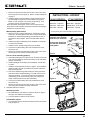
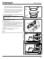
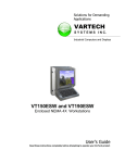
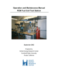
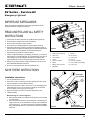
SV Series – Survive-All
SV Series – Survive-All
Emergency Light unit
IMPORTANT SAFEGUARDS
When using electrical equipment, basic safety precautions should
always be followed including the following:
READ AND FOLLOW ALL SAFETY
INSTRUCTIONS
1.
2.
3.
4.
5.
6.
7.
8.
9.
All servicing should be performed by qualified service personnel.
Do not let power supply cords touch hot surfaces.
Do not mount near gas or electric heaters.
Use caution when handling batteries. Avoid possible shorting.
Equipment should be mounted in locations and at heights where it
will not readily be subjected to tampering by unauthorized personnel.
The use of accessory equipment not recommended by the
manufacturer may cause an unsafe condition.
Caution: If optional Halogen cycle lamp(s), symbol (H—), are used in
this equipment, to avoid shattering: do not operate lamp in excess of
rated voltage, protect lamp against abrasion and scratches and
against liquids when lamp is operating, dispose of lamp with care.
Halogen cycle lamps operate at high temperatures. Do not store or
place flammable materials near lamp.
Do not use this equipment for other than intended use.
Figure 1
Part List
1. Tamper-proof screws (6)
9. Gasket
2. Clear cover
10. AC harness
3. Screw gasket
11. Ground wire
4. Lamps
12. Wire nut
5. Electronic module
13. J-box (not supplied)
6. Battery
14. J-box screws (not supplied)
7. Battery strap or bracket
15. Screw cover
8. Backplate
SAVE THESE INSTRUCTIONS
knockout
for conduit
Installation Instructions
1. Turn off unswitched AC power.
2. Open clear cover by removing the screws making sure not to loose
the screw gaskets. Remove lamp protectors.
3. Remove the electronic module. Pull on the cover until snapping features disengage or use a screw driver by inserting it into the slots
shown in figure 12 and prying the cover open.
4. Remove the battery in order to access the knockouts (k’out).
5. Install back plate:
Wall mounting on a junction (figure 2)
a. Route unswitched AC circuit wires into the junction box and leave
6” of wire length.
b. Remove the k’outs needed to mount back plate. Considering the
weight of the unit, it’s recommended to use key hole for additional
securing(see fig.4). For Nexus wired option, install the liquidtight
fitting, provided with the unit. Use the k’out located on the bottom
of the unit.
Emergi-Lite
Tel: (888) 552-6467
Fax: (800) 316-4515
Figure 2
www.emergi-lite.com
knockout for
Nexus data cables
10/13 750.1518 Rev. B
1/4
SV Series – Survive-All
c. Remove AC harness from electronic module. Wire to AC circuit
wires using wire nuts (see figure 2). Refer to hookup instructions
on page 2.
d. Install the gasket on the back plate. Feed AC harness and the
ground through the large hole in the backplate (see figure 2).
Mount to J-box using the J-box screws (not provided). J-box
should be properly secured directly to a stud.
Note: When back mounting the unit on uneven surface such as
brick, silicone caulk should be used to prevent water from seeping in
between the unit and the J-box.
INSTRUCTIONS - HOOKUP
- 120 VAC OPERATION White wire - Common
Black wire - 120V Line
Green wire - Ground
Wall mounting with conduit
-277 VAC OPERATIONWhite wire - Common
Orange wire - 277V Line
Green wire - Ground
Unused primary wire must be insulated to prevent shorting
a. Remove k’out on top of the backplate for conduit entry and key
hole k’out to fix the backplate to the wall. For Nexus wired option,
install the two holes liquid tight fitting, provided with the unit, on
the bottom of the back plate. Don’t route data cables with AC
wires.
b. Install a liquid tight conduit fitting on the backplate. Conduit size:
1/2” NPT (not provided).
c. Install the unit on the wall using screws (not provided).
d. Connect the conduit to fitting and route unswitched AC circuit
wires in the unit.
e. Remove AC harness from electronic module. Wire to AC circuit
wires using wire nuts. Refer to hookup instructions..
To ensure watertightness:
install the screw gaskets
inside the unit, as shown.
Put the screw in the lens
hole and than install the
screw gasket.
Figure 3
Pole or I-beam mounting (Option)
a. Universal bracket (part 16 on figure 4) is an accessory and needs
to be ordered separately. Remove knockouts on top of the backplate for conduit entry.
b. Install a liquidtight conduit fitting on the backplate. Conduit size:
1/2” NPT.
c. Install the universal bracket as shown in figure 4. Don’t install the
gasket (9). Note: this type of installation is not NSF certified for
food processing areas.
d. Unit can be installed using steel banding for routing around the
poles and I-beam. Standard banding ¾" in width or less can be
used (not provided). It can also be mounted on Superstrut®
metal framing (1 5/8" channel series) using 1/4" bolt (not provided). Holes are placed at 9" apart horizontally.
e. Connect the conduit to fitting and route unswitched AC circuit
wires in the unit.
f. Remove AC harness from electronic module. Wire to AC circuit
wires using wire nuts.Refer to hookup instructions.
6. Complete electrical connection:
Figure 4
key-hole
Standard product:
a. Re-install batteries and electronic module as shown on figure 5.
See figure 6 for batteries wiring diagram.
b. Connect transformer harness to AC harness.
Cold weather option:
a. Connect battery heater (18) to thermostat (19) and to AC harness
(10) (see figure 7).
Figure 5
Emergi-Lite
Tel: (888) 552-6467
Fax: (800) 316-4515
www.emergi-lite.com
10/13 750.1518 Rev. B
2/4
SV Series – Survive-All
b. Refer to figure 8 for 120VAC input voltage and to figure 9 for
277VAC . Use wire taps provided with the hardware kit to connect
battery heater. Unused wires must be insulated to prevent shorting.
c. Re-install the batteries. Battery heater is placed between the battery and the backplate. See figure 6 for battery wiring diagram.
Re-install the electronic module as shown on figure 5.
d. Connect transformer harness to AC harness.
7. For unit with remote capacity, connect remote heads to terminal L+ and L- (see figure 11).
Calculation of total allowable remote capacity of unit:
Maximum remote lamp power = unit capacity minus the total power of
lamps included with unit.
Figure 6
8. Snap electronic module on backplate.
9. Adjust lamp aiming.
10.Install the lens by using the 6 tamper-proof screws (1). To
insure water tightness, gasket screws (x6) have to be installed
from the inside (see figure 3). Tighten the screws approximately 5 Lb.-Ft. DO NOT OVER TIGHTEN.
11. For food processing areas, in order to avoid food accumulation, screw caps have to be installed (provided with the hardware kit).
12.Energize AC. Lamps will turn on for few minutes.
13.See page 4 for testing procedure.
Nexus:
FOR COLD WEATHER
OPTION ONLY
Figure 7
For connections related to Nexus system, refer to Nexus Addendum.
120V
Figure 8
277V
Figure 9
Emergi-Lite
Tel: (888) 552-6467
Fax: (800) 316-4515
www.emergi-lite.com
10/13 750.1518 Rev. B
3/4
SV Series – Survive-All
Unit testing
Manual Testing
Operate the magnetic test switch by holding the provided magnet near
the status LED, where indicated. This will initiate a one minute test and
the lamps will illuminate. At the end of the test, the unit will automatically
return to stand by mode. Test can be cancelled by holding the magnet
near the test switch again.
o
Magnetic test
Automatic Testing and diagnostics
The automatic testing and diagnostic function includes a microcontroller which self-tests the unit on a monthly basis and identifies as well displays failures of the electrical components: battery,
battery charger and lamps.
LED Status
Figure 10
Self-test
The self-test is performed every month for 1 minute, every 6 months
for 30 minutes, and annually for 90 minutes.
Diagnostic function
The diagnostic function uses an external red LED indicator. Service
is required if the red LED is present indicating that an alarm condition
is detected (See fig. 10).
o
Green
Steady On
AC On
o
Red
Steady On
Battery Disconnect
-o
Red
Blinking
Battery Failure
o-o
Red
Two Blinks
Charger Failure
o-o-o
Red
Three Blinks
Lamp Failure
Figure 11
For Nexus models, refer to “Nexus addendum” and for additional information about the Nexus system, go to “www.nexus-system.com”.
For more information about the AD function, please consult the web site
for this user manual:
“AD with Single LED Status User Manual”
Food processing facilities
Screw covers are available in the hardware kit. These covers
have to be installed on screws to avoid any food accumulation.
Note: some detergent used in food processing industry can affect
durability of Polycarbonate lens. Install unit on even wall surface
to insure watertightness and avoid any gaps between the gasket
and the wall.
Figure 12
Maintenance (All Models)
None required. If AC supply to the unit is to be disconnected for 2
months or more, the battery must be disconnected.
Emergi-Lite
Tel: (888) 552-6467
Fax: (800) 316-4515
www.emergi-lite.com
10/13 750.1518 Rev. B
4/4