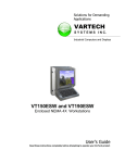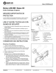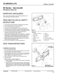
1
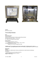
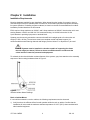
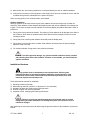
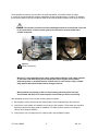
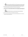
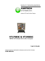
Solutions for Demanding Applications
VARTECH
S Y S T E M S I N C.
Industrial CRT and Flat Panel Displays
VT170ESC & VT190ESC
NEMA 4X Enclosed All-In-One Computer
User’s Guide
Read these instructions completely before attempting to operate your new Color Display
USER MANUAL
Model Number:
VT170ESC ______ (17” display)
VT190ESC ______ (19" display)
Serial Number: ________________________________
Copyright © 2006. All rights reserved.
January 2006
VT170 & 190ESC
2
150-113
Table of Contents
CHAPTER 1: INTRODUCTION AND OVERVIEW
4
ESC Series Industrial Computer
Using This Manual
Safety Information
Receipt of System Components
4
4
4
4
Overview of System Features
NEMA 4x Enclosure
Cooling System
Shock Resistance
Electrical Protection
4
4
4
4
4
Technical Specifications
Fans
Environmental
Mechanical
5
5
5
5
CHAPTER 2: INSTALLATION
6
Installation Requirements
Rack or Cabinet Mount
Outdoor Installation
6
6
7
Installation Hardware
Wiring Requirements
Connecting Power
7
8
8
CHAPTER 3: MAINTENANCE AND REPAIR
11
Cleaning
11
Preventive Maintenance
Check Every Three Months
11
11
APPENDIX A: SUPPORT INFORMATION
12
VarTech Systems, Inc. Technical Support
12
VarTech Systems, Inc. Limited Warranty
12
VT170 & 190ESC
3
150-113
Chapter 1: Introduction and Overview
ESC Series Industrial Computer
Using This Manual
This manual covers installation and service of components, enclosures and cooling systems.
•
•
•
•
Chapter 1
Chapter 2
Chapter 3
Appendix A
Introduction and Overview
Installation
Maintenance and Repair
Technical Support and Warranty
Safety Information
Caution and Warning statements are used to draw attention to vital information:
Caution! If you do not follow instructions, there is a risk you may damage the equipment.
Warning! Hazardous voltage are present. If you do not follow instructions, there is a risk of
electrical shock and danger to personal health.
Receipt of System Components
When receiving delivery, carefully check the packing crate/carton for damage that may have been
incurred during shipment. If any packaging material is damaged, notify the local carrier and submit a
report to VarTech Systems, Inc.. Remove the packing slip and confirm that all ordered components are
present. Make sure no spare parts or accessories are discarded with the packing material. Please do not
return equipment to VarTech Systems without a Return Material Authorization (RMA) number. See
Appendix A.
Overview of System Features
NEMA 4x Enclosure
Systems are built to meet or exceed NEMA 4x requirements. Dust, dirt, dripped or hose-directed water, oil
and coolants are effortlessly shrugged off by the enclosure.
Cooling System
ESC Series uses a sophisticated closed loop thermal management system. Heat generated internally is
efficiently ejected through the use of bi-planar finned aluminum heat exchangers and a forced convection
plenum. High reliability fans provide air circulation.
Shock Resistance
ESC series are mounted on shock absorbing bushings to prevent damage to sensitive electronic
components.
Electrical Protection
ESCs include a surge suppressor for voltage surge protection and reliable power.
VT170 & 190ESC
4
150-113
Figure 1
ESC series computer
Technical Specifications
Fans
Dual 50 cfm (19 lps)
12 VDC, 230 mA
Stainless steel ball bearings; locked rotor and polarity protected
Operating temperature range: –10°C to 70°C
UL Yellow Card recognized; CSA certified
Environmental
Temperature (Per IEC 68-2-1,2,3,14):
Operating 0°C to +50°C*; Storage: -20°C to +65°C
Humidity (Per IEC 68-2-1,2,3,14):
Operating 10% to 95%; Storage 5% to 95%
*Operation at 50°C is possible but may shorten component life. Operation at 35°C or lower is
recommended. If prolonged operation at over 35°C is needed, a high temperature option is available.
Mechanical
Material:
- Brushed 316L stainless steel door/ring; extruded aluminum back frame/heat exchanger
Dimensions:
- 18 inches x 20 inches x 15.5 inches (H x W x D)
- 610 mm x 508 mm x 394 mm (H x W x D)
Weight: 65 lbs. (40 kg)
VT170 & 190ESC
5
150-113
Chapter 2: Installation
Installation Requirements
Mounting hardware supplied for easy installation. When determining the location for mounting, keep in
mind the weight of the unit, available power connections, and access to peripheral equipment necessary
for system operation. If installing a system outdoors, be certain to read the recommendations for outdoor
installation provided elsewhere in this manual.
ESCs require 4 Amps maximum at 120VAC, and 2 Amps maximum at 230VAC. Note that the unit is autosensing between 120VAC and 240 VAC. We recommend using 14-16 AWG wire and a 10-15A
2-pole breaker in providing input power to terminal block.
Systems must be securely mounted to a structure that will hold a weight equal to four times the unit
weight (TS 500 = 66 lbs). The enclosure must have complete vertical and lateral support. It is
recommended that metal framing channels and fittings (such as Unistrut™ or Superstrut™) be used.
Caution! Systems must be installed in a location capable of supporting four times
the unit weight (see above). Failure to choose a suitable structure could cause the
unit to become a hazard to personnel and equipment.
To maintain the shock and vibration resistant features of the systems, pay close attention to the assembly
sequence of the mounting hardware shown in Figure 2.
Figure 2
Vibration Isolator Mount Bushings
Rack or Cabinet Mount
If a unit will be mounted in a rack or cabinet, the following requirements must be observed:
1) Verify that there is sufficient airflow for safe operation within the rack or cabinet. Confirm that the
installation will not exceed the maximum ambient temperature of 122°F (50°C) when combined with
other installed equipment.
VT170 & 190ESC
6
150-113
2) Make certain the unit mounting hardware is not compromised by the rack or cabinet installation.
3) Verify that the connection of the equipment to the supply circuit does not overload the circuit, and that
a reliable earth ground is maintained for the power connection.
Other mounting options, such as desk stands, are available.
Outdoor Installation
Although systems are dust and moisture proof, solar radiation from direct sunlight can overheat the
enclosure. Solar radiation will also degrade the display window and reduce readability of the display due
to glare. To minimize the impact of solar radiation, the following display orientations are listed in order of
preference:
1) Facing north is the preferred orientation. The majority of solar radiation will be directed at the sides of
the enclosure, which have the smallest surface area. Minimum direct sunlight will fall on the heat
exchanger panels.
2) Facing east is fair. Morning solar radiation will directly heat the display area.
3) Facing west is poor and should be avoided. Solar radiation will directly heat the heat exchanger
panels for most of the day.
4) For southern latitudes, facing south is the preferred orientation.
Caution! To avoid equipment damage, any system installed outdoors must be provided
with shielding from direct solar radiation. If shelter is not available, you must install the
optional sunshield.
Installation Hardware
Warning! systems must be installed by trained professionals, following safe
industrial practices for electrical equipment installation and maintenance. If the
instructions in this manual conflict with local laws and requirements, then local
laws and requirements should prevail.
Tools and materials required for installation:
1)
2)
3)
4)
5)
Mounting hardware (included)
Metal framing channels (Unistrut™ or Superstrut™ recommended)
Hardware to attach the product to the framing channel
Wrench to tighten the mounting hardware
Carpenter's level, measuring and marking instruments
Caution! Failure to provide and maintain adequate environmental seals to conduit
fittings during and after installation can damage the system and expose the user to
hazardous voltages.
After gathering the necessary tools and determining the general location for the installation, proceed as
follows:
VT170 & 190ESC
7
150-113
1) Identify the specific location and position at which the unit is to be installed. Make sure to allow
sufficient clearance for conduit and/or cable connections. Mark the mounting surface where the top
edge and one side of the enclosure will be aligned.
2) The mounting points of the unit are located in a rectangular pattern 18.5” wide by 15” high. The
mount points are ¾” from the sides and 1½ ” from the top and bottom of the installed enclosure. The
standard unit comes with four 3/8”-16 bolts that are sized to work with threaded wall anchors or
channel nuts. Other mounting options, such as stands, are also available.
3) There are four rubber isolator assemblies in the mounting kit. Each isolator assembly is comprised of
two parts, a donut-shaped part and a T-shaped part. Insert a mounting bolt into the donut-shaped part
and insert it into the large holes on the front of the mounting flange on the back of the enclosure.
4) Install the T-shaped parts to the mounting holes on the rear of the enclosure and seat the donut
shaped parts onto the T-shaped parts. Note that the T-shaped parts fit very tightly in the mounting
hole.
5) Lift the unit into position and tighten bolts.
Wiring Requirements
We recommend using the supplied NEMA 4 (IP66) rated conduit connectors on the bottom panel of the
enclosure for routing power and signal lines, or other NEMA 4 (IP66) rated conduit connectors. The
standard configuration includes two 1-inch trade-size liquid tight conduit fittings. Other configurations,
including sealing fittings and bulkhead connectors, are available.
It is strongly recommended that installations include a flexible section of conduit; for example, three feet
of conduit or two feet of tubing to allow the shock and vibration isolators a full range of motion.
Connecting Power
Most units ship with conduit holes pre-punched. If the unit was ordered without pre-punched holes:
1) Drill a small pilot hole in the bottom panel for each conduit entry.
2) Use a Greenlee punch (or equivalent) to create a suitable hole.
3) Verify that the holes are free from burrs or sharp edges and all chips and metallic debris are removed
from the enclosure. All chips and metallic debris must be removed from the enclosure before
operation to prevent damage to the installed electronic equipment.
Warning! To avoid potential electric shock, follow National Electric Code safety
practices or your local code when wiring and connecting this unit to a power
source and to electrical sensors or peripheral devices. Failure to do so could result
in injury or death. Only qualified personnel should perform wiring procedures.
Warning! Before proceeding, make sure that incoming electrical power has
been disconnected and there is no electrical power on the leads you will be
connecting.
VT170 & 190ESC
8
150-113
These standard connectors are intended to be used with flexible, nonmetallic conduit or tubing.
It is strongly recommended that computer installations include a flexible section of conduit, for example,
three feet of conduit or two feet of tubing to allow the shock and vibration isolators a full range of motion.
Caution! The conduit connectors must be sealed against adverse environments. If the unit
is not connected to a closed conduit system, the connectors must be sealed with a
suitable compound.
Terminal Block
Ground Stud
Figure 3
Power Connections
Warning! To avoid potential electric shock, follow National Electric Code safety practices
or your local code when wiring and connecting this unit to a power source and to
electrical sensors or peripheral devices. Failure to do so could result in injury or death.
Only qualified personnel should perform wiring procedures.
Warning! Before proceeding, make sure that incoming electrical power has been
disconnected and there is no electrical power on the leads you will be connecting.
After preparing the entry holes, connect incoming power as follows:
1) De-energize incoming electrical power (mains power). Route conduit/wiring to the enclosure.
2) Verify that a circuit breaker is installed in the line prior to the computer. The breaker size should be
determined by the wire gauge used for installation. TS 500s require a maximum of 4 Amps at
120VAC and 2 Amps at 230VAC.
3) Verify that the unit is configured for the voltage used in the installation location.
VT170 & 190ESC
9
150-113
Caution! The incoming power switch must be set correctly before powering the computer.
Failure to do so may cause serious damage to the equipment and or injury to personnel.
4) Connect the ground wire to the ground stud in the bottom of the enclosure as shown in Figure 2. A
wire runs from this stud to the terminal block. This wire must remain connected.
5) Connect 110/220 VAC, 50/60 Hz power to the Mains Power terminal block inside the enclosure. Make
sure that the “L1/L,” “L2/N” and “GROUND” leads are correctly connected to the marked positions.
Caution! For safe system operation, the neutral and ground wire must be properly
connected.
6) Secure the conduit connectors as recommended by the manufacturer.
7) Do not cover the rear extrusion of the unit with any material that will hamper the free air exchange
needed to maintain the cooling system.
VT170 & 190ESC
10
150-113
Chapter 3: Maintenance and Repair
Very little maintenance is required. The enclosure is watertight but should be checked regularly to ensure
that all components are operating properly. Contact VarTech for assistance and/or to order spare parts.
Cleaning
Systems are housed in stainless steel enclosures. The enclosure may be cleaned with a variety of
industrial cleaners or solvents. To prevent discoloration or deterioration of the enclosure finish, avoid
prolonged contact with acids or strong solvents. Systems may be hosed down safely.
Preventive Maintenance
Check Every Three Months
Internal Components
1) Fans
a) Verify that the computer fan is operating
b) Check that the power supply fan is operating.
c) Verify the heat exchanger fans are operating.
2) Verify that all cable connectors are securely fastened.
3) Check door seal for nicks, breaks or loosened mounting adhesive.
4) Verify that all conduit and cable connections are secure.
5) Check all cables for nicks, frayed or damaged insulation. Check closely the area where the wiring
crosses the enclosure’s hinge line.
6) Verify the cables clear of any sharp edges and loop correctly when the door is closed.
External Components
1) Check heat exchanger cooling fins for excess buildup of dust, dirt or other materials that could reduce
the system’s heat rejection. Clean the fins by flushing with air or water.
2) Check for loose mounting screws and worn or broken vibration isolators.
3) Check for cracked or loose display window.
VT170 & 190ESC
11
150-113
Appendix A: Support Information
VarTech Systems Technical Support
For technical support and repairs, please contact Vartech SystemsTechnical Support at: (800) 223-8050
or (225) 298-0300, Monday through Friday, 7:00 am to 4:30 pm CST, excluding holidays. Fax: (297) 2972440.
VarTech Systems Limited Warranty
VarTech Systems, Inc. warrants this enclosure against defects in material or workmanship, provided the
serial number appears on the product and is as originally configured by VarTech.
If failure of the product has resulted from accident, abuse, or misapplication, VarTech Systems, Inc. shall
have no responsibility under this limited warranty.
Corporate Headquarters
VarTech Systems, Inc.
11529 Sun Belt Ct
Baton Rouge, LA 70809 USA
800-223-8050
[email protected]
www. vartechsystems.com
VT170 & 190ESC
12
150-113